Archive for December, 2006

Mounted ELT

Sunday, December 31st, 2006

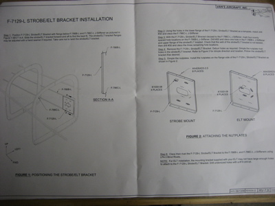
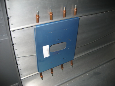
The plans that come with the ELT mounting bracket are similar to the plans for the RV-10 and the new prepunched RV-8. Compared to the vague and confusing RV-7/9 plans, the new style is practically a comic book that shows you how to pound airplane parts together. You RV-10 builders don't know how easy you've got it. (Note to pre-quickbuild RV builders: Please don't email me with stories about how you had to mine your own bauxite from the Earth's crust and turn your own rivets on a lathe – I already know the kit could be a lot worse.)

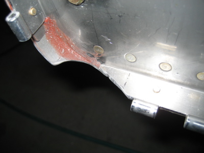
The rivets that attach the lower flange of the ELT bracket to the bottom J-channel stiffener are really hard to get to. In order to drill the holes, you need to use a 1/2" stubby drill bit in an angle drill. I also had to use a mirror just to figure out where the prepunched holes were.

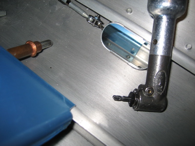
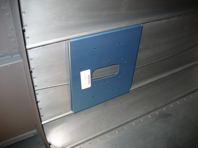
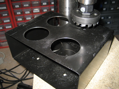
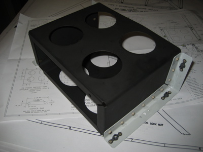
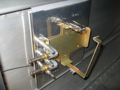
Here's the bracket with all the holes drilled:

After all the holes were drilled, I pulled the bracket out of the fuselage, deburred it, primed the back side and the mating flanges, and installed the nutplates. You actually only need to put nutplates in four of the eight prepunched positions, since half the holes are for the ELT and the other half are for mounting a strobe power supply. However, I figured that since I won't be able to remove the bracket later, and I'm not 100% sure I won't need to mount something else here instead, I might as well go ahead and put nutplates in all eight holes. I may thank myself later, who knows.

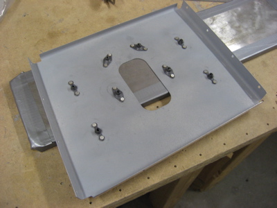
I used K1100 dimpled nutplates in the four holes that the ELT attaches to, so I could also dimple the ELT mounting tray and not have to worry about protruding screw heads underneath the ELT itself. The plans would have you use round-head screws here, which doesn't make much sense to me.

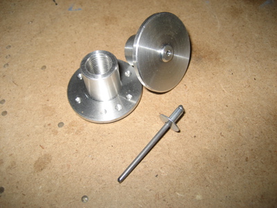
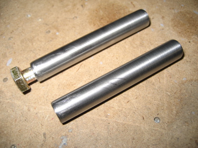
Finding a way to actually pull the rivets on the bottom side is harder than drilling the holes. The curve of the fuselage gets in the way, so you need to use rivet puller that's as short as possible. I ordered a supposedly low-profile riveter from Avery just for this task, but it turned out to actually be even bigger than the other two riveters in my toolbox – a cheap Arrow-brand puller from the hardware store, and a Powerlink riveter, my usual blind riveting weapon of choice, also from Avery. Click the image below for a comparison of rivet puller sizes:

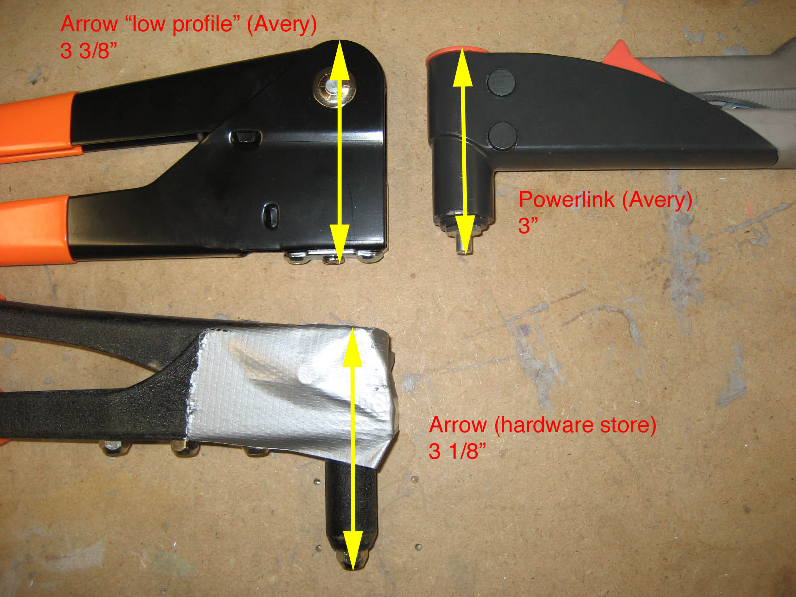
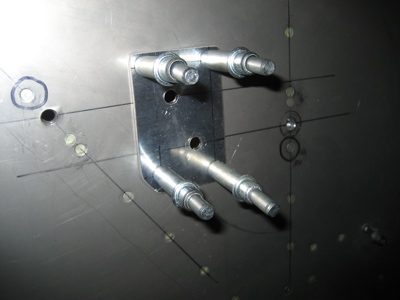
I ended up finagling the Powerlink riveter down in there, although the lower rivets are still a little tipped. I think this is pretty unavoidable given the geometry of the bracket, stiffener, and skin.

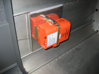
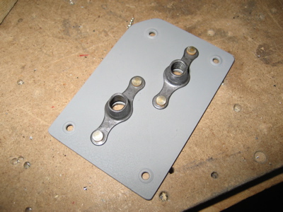
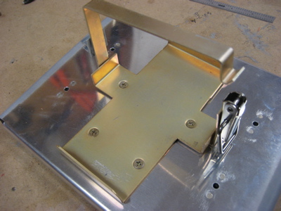
After all that, I wasn't happy with how floppy the ELT mount was. You could grab it with your hand and literally bend it back and forth. That seemed pretty dumb, considering how this thing is supposed to survive an airplane crash. Since the bracket was already riveted in place for good, I decided about the only thing I could do was find a way to tie the front end of the ELT tray to the bracket more securely.

Here we go – two more flush screws attach the tray to an aluminum angle that I pop riveted to the bracket. It's still not perfect but it's a lot sturdier. Now when you grab the ELT and try to shake it, it mostly moves around inside the tray – unavoidable since it's only held in place by that strap thingy – instead of the tray itself moving around like it did before.

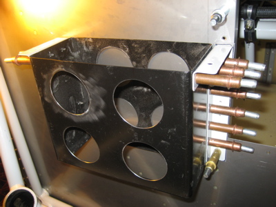
Update: The Van's ELT bracket turned out to be a stupid idea. See this entry for the alternate ELT mounting location I eventually decided to go with.

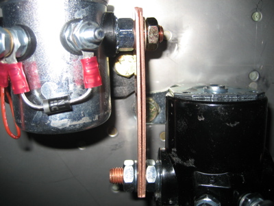
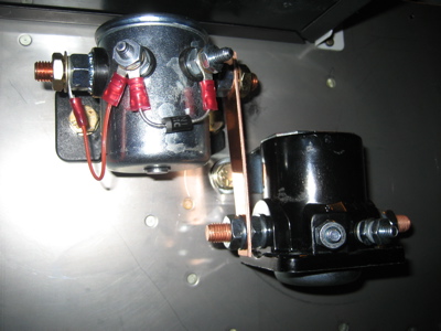
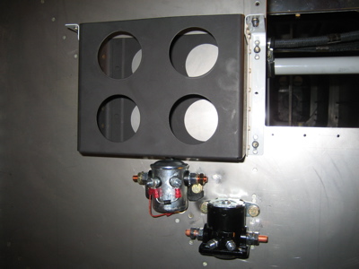
While I was messing around in the garage, I noticed that the plans actually call for a pair copper bars between the master and starter relays, not just one like I had, so I quickly fabricated another chunk of copper and slapped it on there.

Boxing day work

Tuesday, December 26th, 2006

Happy Boxing Day, whatever the heck that is. I celebrated the halfway decent weather by going flying.

I also did a few small chores on the airplane, or tried to. First I thought I'd install the ELT. My first location – directly behind the seat – turned out not to be so hot after all for a couple different reasons. For one thing, the downward angle of the floor behind the seatbacks is about 15-20 degrees off the waterline of the aircraft, more than the maxinum 10 degrees allowed by the ELT installation manual. Furthermore, if the seatback was installed in its aftmost position, the upholstery would tear itself up on the ELT and its bracket – not so good.

So, after playing with various ideas for a while, I finally decided that using Van's bracket kit (which I already have) to mount the ELT on the fuselage sidewall, right behind the baggage bulkhead, would be about as simple as anything. Unfortunately I discovered that I need a shorter #30 threaded drill bit and a smaller pop riveter to get back in there and install the thing, so all I was able to do with the ELT bracket today was look at it.

Then I decided to finish the cutouts in the lower firewall flange so the gear legs can eventually be installed in the engine mount. Since the fuselage is currently too low to the ground to get the actual gear legs under there, I had to improvise a fake gear leg tube out of a PVC pipe coupler and some duct tape to help it stay inserted in the socket. That made it very easy to eyeball the fit and mark out the areas that needed to be trimmed.

After three or four iterations with the Dremel tool and various forms of scotchbrite, I was able to get a nice uniform clearance all the way around. I should add that since I had to lay on my back underneath the airplane while I was doing this, I got aluminum and steel "snow" all over me in the process. Yuck. I wore safety gear and took a shower right afterwards so it wouldn't get into my eyes.

Here's the shape of the finished cutout. You can see that the outermost rivet hole is entirely obliterated. If I had waited to install the lower cowl hinges until after I'd finished these cutouts I could have saved myself an extra inch of hinge material, but oh well. I suppose I should be grateful that the amount you're required to cut isn't another 1/8" deeper, or else it would start chewing into the firewall itself.

Another small puzzle I spent some time looking at tonight is the location and nature of the static ports. The plans would have you put a pop rivet into the fuselage skin on each side of the airplane, then pound out the mandrels and glue the ends of the plastic static tubing over the resulting hollow rivet shafts. Uh, no thanks. I had that setup on my last RV, and it gave me terrible static leaks until I replaced the cheesy rivets with a pair of Cleaveland static ports. I have a pair of nice looking machined static fittings (see photo below) that I picked up from Safeair in a moment of weakness, but I've heard of people having problems with them because they don't stick out far enough into the slipstream. It turns out that a static port that's too close to being flush with the skin doesn't do a very good job, and the Cleaveland ports stick out further than the Safeair ones. I may end up scrapping these and getting another pair of the Cleaveland ones instead.

I got as far as marking the static port locations and drilling a #40 pilot hole – one on either side of the fuselage, positioned as described in the plans. They'll be tee'd together to cancel out errors induced by side slips.

It's a loooong way back there into the tailcone where the static ports are. I can forsee this particular bit of plumbing is going to be a real joy to install.

More work on battery box and relays

Sunday, December 24th, 2006

What's this, some kind of new kind of device for keeping your pennies organized?

Nope, it's just the holddown strap for the battery. I cut the optional lightening holes to take away some of the mass of that hefty alunimum bar, and painted it to match the battery box just because I felt like it.

Down below, the input side of the starter relay is now connected to the output side of the master relay via a copper bus bar.

Interestingly, the prescribed mounting orientation for the starter relay is such that positive G forces will tend to open the relay instead of forcing it closed – there's a note in the plans about this. I guess they are concerned that the starter might kick in at the bottom of a loop?

Installed battery box and relays

Saturday, December 23rd, 2006

The battery in the RV-7 lives in a steel box on the forward side of the firewall. The basic box itself comes already formed, spot welded, and powder coated black. You can optionally cut some lightening holes in it, which I chose to do. The combined weight of all the material I removed with my Rotabroach cutter was something like a quarter pound – that's one more cheeseburger I can eat without putting the airplane over its maximum gross weight.

The battery box bolts to the firewall stiffeners through three holes that you have to drill the rivets out of.

Here's the battery box and its steel support angles being fitted to each other and to the firewall. (once again the angle drill was put to work for this task) If you look closely you can just barely see the 0.020" alclad spacer between the firewall and the bracket on the port side of the airplane (right side of this photo) that simulates the thickness of the stainless firewall recess that will eventually be sandwiched between the firewall and the bracket.

Did you notice in the previous photos that the powder coating on the battery box got pretty scratched up while I was cutting the lightening holes? That plus the exposed steel edges inside the holes themselves was enough to make me decide to repaint it. I scuffed it up and sprayed it with a coat of some black high temperature barbeque grill paint that I had in the garage. It seems like it will be fairly durable.

Then I riveted on the support angles and nutplates – in that order, since the nutplates block access to some of the other rivets. You also have to remember to dimple the box and angles from the inside out, so the flush heads will let the battery slide in and out without getting hung up.

Lots of careful measuring is required to properly position the holes for mounting the master and starter relays. The outer two holes go through the firewall stiffeners, and the inner two holes go through this little 0.063" doubler. Also, the two circled rivets have to be drilled out so the two outer nutplates can be attached to the stiffeners.

Here's the doubler, primed and with the 1/4" nutplates attached. This gets riveted to the aft side of the firewall.

Here's the battery box, master relay (silver), and starter relay (black) bolted in place. What's interesting is that the heavy battery (14 pounds or thereabouts) is held to the firewall with three 3/16" bolts, and the comparatively lightweight relays (about a pound each) are held in place with a pair of 1/4" bolts apiece. I hope that battery doesn't go anywhere or I shall be sorely put out.

Also worth recording is the fact that I bought my master relay from B&C instead of Van's, since it's an important component and Van's is known for carrying cheap stuff (IMHO). It was almost twice as expensive, and it actually may not be any more reliable, but it makes me feel better to have it. The mounting holes are identical to the one Van's sells so no problem there.

The starter relay, on the other hand, is Van's stock item. The one that B&C sells appears to have totally different mounting lugs, so it would have been a pain to install, and I'm a lot less worried about safety implications of my starter relay conking out.

Installed the engine mount

Saturday, December 16th, 2006

I made two bushings out of 3/8" OD 0.058" wall steel tube, each about two and a half inches long. 1/4" bolts fit nicely inside.

I used the bushings and bolts to temporarily attach the mount to the firewall, using the pre-drilled 1/4" holes. I used the two upper corners for this, but I think you could do it with whichever pair of holes lines up best.

Immediately it became apparent that I needed to remove some of the firewall flange at the lower corners where the gear sockets are. Checkoway has a better photo on his site. I used a grinding thingy in my Dremel to make the rough shape, then filed and scotchbrited it smooth. I think I'll have to come back and open this up further when I go to insert the gear legs, but right now it's trimmed enough to at least get the engine mount onto the firewall.

One hole at a time, I drilled up to just a bit less than 3/8" using a U-size drill bit (0.368") then reamed up to 0.375". At the two lower center bolt locations, the mount was spaced away from the firewall a bit, so I made some spacers out of alclad scraps. I think I used 0.032" for one and 0.016" for the other.

After the holes were drilled, I made the spacers all round and pretty:

Huzzah, the engine mount is on the fuselage. I didn't torque or safety the bolts, as I'm sure I'll have it on and off a few times before it's bolted on for good.

Yep, it's plenty strong.