Archive for January, 2008

Rolling on the gear

Saturday, January 26th, 2008

I reamed the bolt holes in the engine mount's gearleg sockets to 0.311", which is a few thousandths undersize for a 5/16" bolt. The goal is to have a zero-slop press fit for the bolts that go here, to keep them from elongating their holes as the gear absorbs loads during use.

I set up Scott's hoist and attached it to the fuselage, using sections of clear vinyl hose material slipped over the engine mount tubes to keep them from getting crunched up by the chains.

"Not to be used for aircraft purposes" – hmm.

Having one end of the the fuselage suspended several feet in the air and the other end supported by a single little wheel induced a certain degree of nervousness.

I had to grind off some of the excess powder coating on the gearlegs to get them to go all the way into their sockets. I also ground a very slight chamfer at the top to keep the rod from getting hung up inside the socket.

Since Mary had other things to do, I had to call and beg Scott to come help me steady the fuselage while I persuaded the gearlegs into the engine mount. The first one went in relatively easily, but the second one was a real pain, especially the last half-inch or so.

I used a low pressure in the rivet gun and a brass-tipped rivet set to drive the bolts home. This worked very well and seems to have resulted in some nice tight-fitting bolts. I need to pick up some AN363-524 metal locknuts, but in the meantime these bolts aren't in danger of going anywhere.

With both gearlegs installed, I put the wheels on the axles so the plane would have something to sit on when lowered to the ground:

The fuselage is on the gear! Suddenly, the airplane is much taller.

Big milestone today. Also, big thanks to Scott for his assistance and the use of his hoist. Don't tell China that I used it to lift an airplane, or they might come take it away.

Installed empennage for good

Saturday, January 26th, 2008

The tailwheel mount shares several bolts with the vertical stabilizer spar, so before you can put any substantial weight on the back wheel you have to install the vertical fin first. I've had the tail propped up on a pile of styrofoam insulation for a long time, but now it's time to get this thing standing on its own feet, or wheels as the case may be.

To provide the proper amount of vertical stabilizer offset, there is a single AN960-10 washer between the spar and the up-elevator stop, on the left side bolt only. This photo confirms that I did remember to install that pesky washer:

I torqued and marked all the bolts that attach the horizontal and vertical stabilizers:

I couldn't get a socket onto some of these, so I just tightened them using a wrench and German torque.

More bolts:

I couldn't get enough access to the nuts on these bolts to apply the orange torque seal goop, so I just marked the bolt heads to remind myself that I did actually torque the bolts.

The horizontal and vertical stabilizers are now mounted permanently, and the tailwheel is capable of supporting real weight. You can't really tell from this photo, but the tail is now resting on the tailwheel instead of sitting on a pile of foam.

How about them packers

Thursday, January 24th, 2008

Tonight I packed the wheel bearings with fresh grease, replacing the preservative stuff that they come filled with. Sorry I didn't get any photos; my hands were too messy to handle the camera.

I've repacked many an aircraft wheel bearing in my time, but I've always done it the low-tech way – globbing in new grease by hand. This time I wanted to try out one of those fancy bearing packer tools. I picked up one of these at Sears, but its plastic housing broke almost immediately. Then I bought one like this, which worked better. It's pretty crudely constructed, but at least it's made of metal. It didn't eliminate the sticky-fingers problem, but using it was somewhat easier than packing bearings by hand. It probably does a more thorough job of getting grease into the bearing, too.

The old-timers' approach is to use Aeroshell #5 for wheel bearings, and #6 for everything else (pivot bushings, etc.). I'm too lazy to keep two different kinds of grease around, so I've always used Aeroshell #22 for everything. (specifications here) It costs a couple bucks more, but one tube is enough to do a half-dozen annuals.

Wheels and tires

Sunday, January 20th, 2008

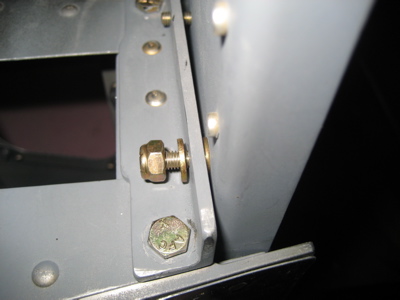
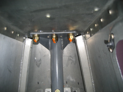
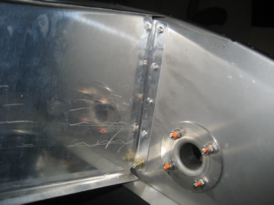
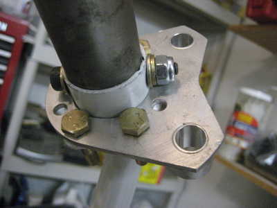
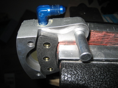
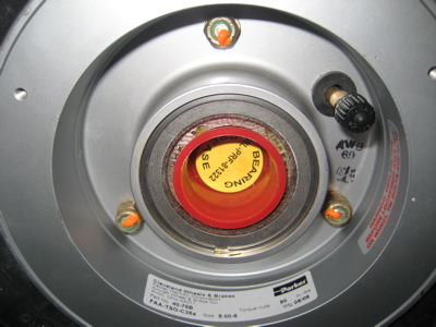
Well, I figured out how the landing gear axle, brake mounting flange, brake mounting plate, and U-810 bracket are all supposed to fit together. You're also supposed to make little 13/32" aluminum spacers to maintain clearance between U-810 (to which the wheel fairing mounts) and the brake disc, but I just used stacks of washers instead. When I had my RV-9A, I accidentally squashed a couple of the aluminum spacers while tightening up some loose bolts – no chance of that happening here.

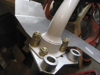
Seven AN960-416 washers stacked up gives you the required 1/16" clearance between the bracket and the brake disc. By the way, my U-810's are actually aftermarket replacement jobbies, made from stainless steel. I'm not sure this is really necessary, but I've had them laying around for a couple years (impulse purchase, again) so I decided to use them. They're heavier than the stock aluminum brackets, but I guess they ought to be pretty much indestructible.

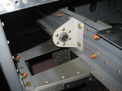
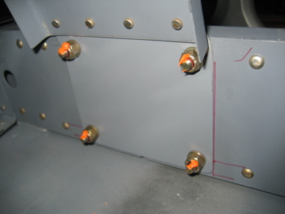
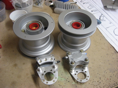
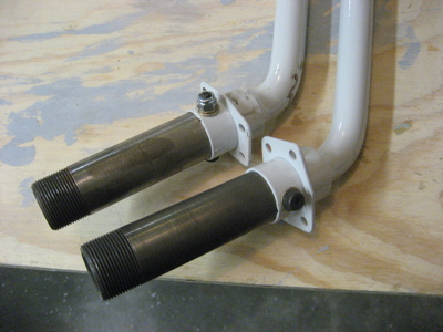
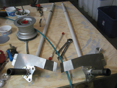
Here are both gearlegs with all the bracketry mounted:

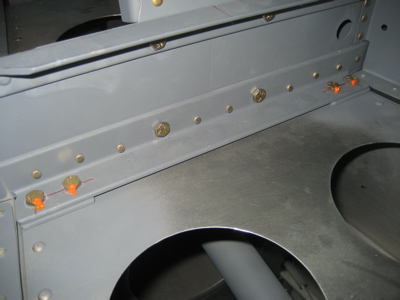
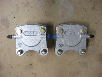
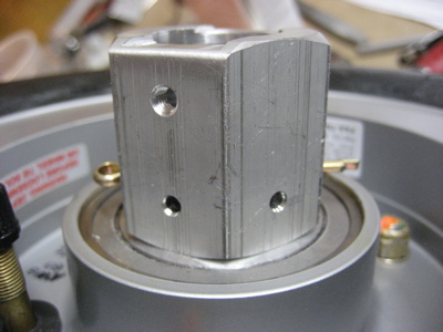
I installed the elbow fittings in the brakes, although I haven't gotten around to mounting the brakes for good just yet. I gooped Bakerseal (teflon paste) on the threads before installing.

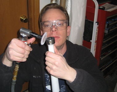
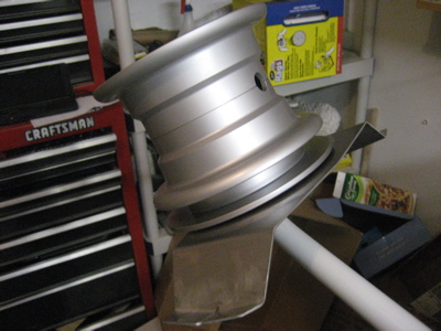
Then I dug the tires and tubes out of storage so I could assemble the wheels. The red dot is opposite the heavy side of the tire, so you line up the valve stem with the dot. One trick I learned somewhere is to put a couple psi of air into the tube after you get it into the tire, before you try to mount the tire on the wheel. When it's just slightly puffed up, it's much harder to accidentally pinch the tube between the wheel halves and ruin it.

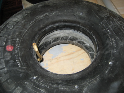
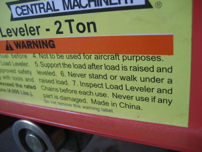
One other thing I want to mention about tires… the tradition is to put talcum powder inside the tire, to keep the tube from sticking to the tire at high temperatures – this is supposed to make it easier to remove the tube later on. I'm not sure if I believe this is really a problem, but when changing tires on my airplanes I've always done it anyway. Today I could only find the baby-fresh kind so that's what I bought. Anyway, I torqued the bolts holding the wheels together to 90 inch-pounds, which is higher than normal but that's what it says on the sticker. I also had to enlarge the hole in the rubber grommet to get the valve stem through without resorting to pounding on it.

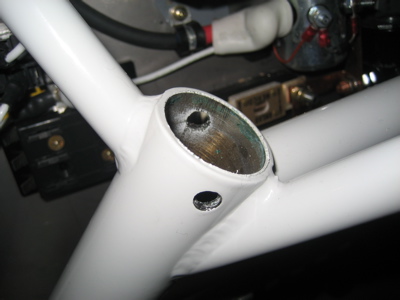
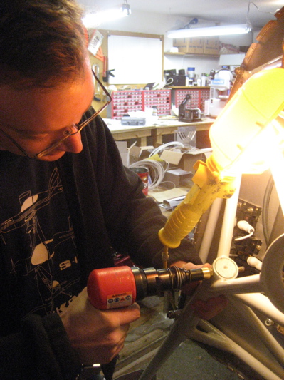
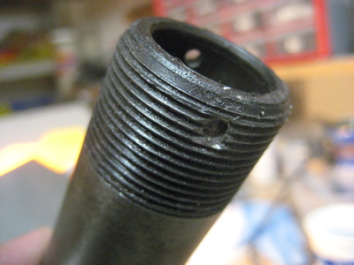
To drill the axles for the cotter pins that keep the nuts in place, I ignored the plans and followed the Tony Spicer method. Basically, it goes like this:

  1. Install the wheel and tighten the nut to where you want it.
  2. Use a 12" #30 drill bit to mark the location of the first hole with a small dimple.
  3. Remove the nut and wheel.
  4. Grind away the threads on the axle in an area about 1/8" in radius, centered on the dimple you made. I used a small hemispherical stone in my Dremel.
  5. Replace the wheel and tighten the nut back to where it was.
  6. Use the 12" #30 bit again to re-mark the dimple for drilling.
  7. Remove the nut and wheel.
  8. Use a sharp #30 bit to drill the first hole through the axle, using the dimple as your guide.
  9. Replace the wheel and nut.
  10. Put a drill bit through the hole you just made, to keep the nut from rotating.
  11. Repeat steps 2-9 for the second hole.
  12. Use the 12" #30 bit to clean out the two holes so a cotter pin will go all the way through.

You end up with nice-looking holes and you don't have to worry about splitting the threads and getting the nut jammed on the axle, which can happen if you use a center punch like the plans tell you.

I installed the wheels and nuts but didn't bend the cotter pins yet, since I'll need to remove the wheels again to pack the bearings.

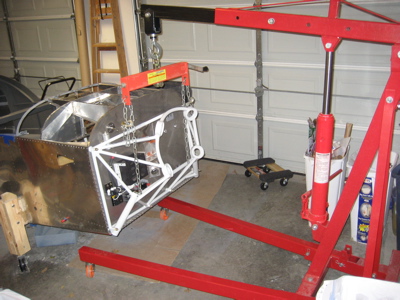
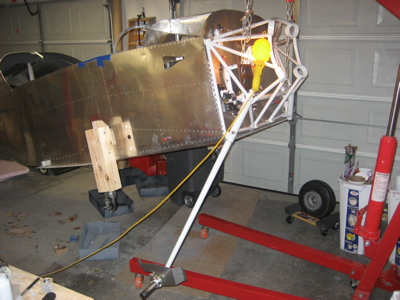
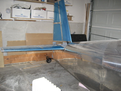
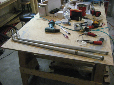
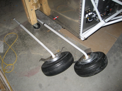
Here's two gearlegs with wheels installed (but no brakes yet) ready to go on the airplane.

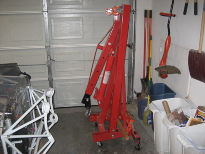
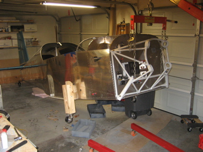
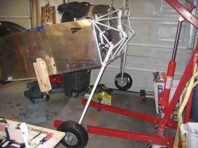
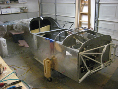
Scott was nice enough to loan me his engine hoist, which I will use to lift up the fuselage for fitting the gearlegs (not to mention for hoisting the engine). I just need to get a few things in order and then it will be gear-attaching time.

Gearlegs & misc

Sunday, January 13th, 2008

The first thing I did on the airplane this weekend was to finish riveting the tricky rivets that I hadn't been able to finish last time I worked on the subpanel/firewall area. While setting the bottom-most rivet on the starboard side, I screwed up the shop head bigtime and had to drill it out (which I didn't do a great job of either, sigh). I discovered that I also managed to crack the very edge of the dimple – from whacking it with the bucking bar, maybe – and decided to drill out the hole to get rid of the crack and use a bolt instead. So now I have this mystery bolt on my firewall:

I fished the gearlegs out of storage and got to work getting them ready to go on the airplane. These things are about the size of golf clubs, but are made out of solid steel and weigh something like ten pounds each.

Here are the Cleveland wheels and brakes. This stuff is all made of magnesium… light but expensive!

I swapped the pressure and bleed ports on one of the brakes so I'd have one left and one right.

These are the U-403 brake mounting flanges, bolted to the gearlegs. It took forever to get these on here, since I had to grind away all the excess powder coating and then polish the outside of the axles with emery cloth to get the flanges to slide into place. Then I needed to ream the pre-drilled but undersized bolt holes up to 1/4". I'm glad the holes in the gearlegs were already there, or else I'd be taking these things to a machine shop… I looked up the properties of 6150 steel, and it doesn't sound like drilling through an inch of the stuff with hand tools would be a lot of fun.

I swear that two hours elapsed between the last photo and this next one. See, the plans for the wheel/brake installation aren't exactly clear. It took me a couple hours of fiddling, head-scratching, and web-searching to realize that if you follow the instructions as they're written and bolt the U-403 flange to the gearleg first, it's impossible to get the brake mounting plate installed because the bolt is in the way. Of course, it wasn't obvious to me which way around things were supposed to go, so I wasted a lot of time trying to get things to fit the wrong way. An exploded view would have saved me a lot of time here, but oh well.

I can't believe that's all I got done on the airplane all weekend. Blah.

Oh yeah, somebody told me I need to take more big-picture pictures so the casual reader might be able to have half a clue what I'm rambling about, so here you go, a photo of the fuselage… soon to be converted from a metal canoe to a real live honest to goodness airplane fuselage on wheels. I hope.