Archive for April, 2008

Mounted main alternator

Sunday, April 27th, 2008

The B&C 60-amp alternator comes with all the hardware you need to mount it to the engine. I first bolted the (very substantial) mounting bracket to the matching boss on the engine:

The two mounting bolts get secured with safety wire, and you also bend up the tabs on the little washer-plate thingy to further immobilize them. Talk about belt and suspenders.

The included spacers put the alternator in just the right position to get the pulleys lined up. Here it's just hanging from the pivot bolt, as the tension arm isn't in place yet.

The alternator came with a Gates 7365 belt:

Oh boy, another little surprise… not only will I have to take the propeller off to replace the belt at some point in the future – probably a most inopportune time – but I also had to pull the ring gear to get the belt past the starter's pinion gear.

Here it is with the tension arm loosely connected. I think I'm going to go find a shorter belt so I can tuck the alternator in closer to the engine and farther away from the cowl.

I also had to replace the belt in our vacuum cleaner yesterday, so this has pretty much been an all-belt weekend.

Installed exhaust

Sunday, April 27th, 2008

I bolted on the exhaust pipes for good:

I put high-temp anti-seize paste on the studs, and torqued the nuts to 120 in-lbs. I also used the included blow-proof gaskets between the pipe flanges and the cylinder heads.

I painted some more anti-seize on the exhaust slip joints before sliding them together. I also dribbled some mouse milk into the exhaust's ball joints.

Look at this little guy. If there was ever a mouse that was more eager to help build an airplane, I don't think I want to know about it.

I taped some plastic caps over the pipe ends to keep critters out.

I used stainless steel clamps to attach a couple of heat shields to the pipes where they come close to the throttle cable. This plus the firesleeve should protect the cable from radiant heat.

Since I had a spare, I also put a heat shield at the top of cylinder #4's exhaust pipe, near where the mixture cables goes by. There's more clearance here than where the throttle cable is, but I figure a little extra heat protection can't hurt.

This is how I safety-wired the hose clamps:

Finished engine controls and throttle quadrant

Sunday, April 20th, 2008

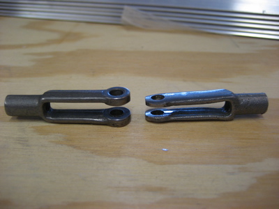
The clevises I am using inside the throttle quadrant are AN481's – actually a special variant threaded for a 10-32 cable end, available from Aircraft Spruce under part number 05-01437. I'm using these because they have sufficient throat depth to avoid getting hung up on the quadrant levers, which is a problem with the AN665's recommended by Van's. But, the AN481's are quite a bit wider, which is a problem when using the closely-spaced DJM throttle quadrant. I fixed this by grinding down the clevis that will be used for the center lever (the prop control) and bending the ears slightly inward to narrow it. With this modification, the AN481 will take the 11/32" clevis pin used by the AN665, instead of the 15/32" pin it comes with. That means it will fit in the same space as the factory-recommended clevis, and won't hang up on its neighbors as it moves. There's still plenty of material left, so I'm not worried about the strength of the modified part.

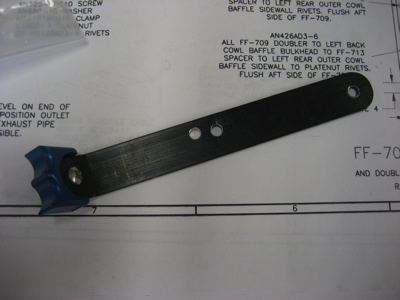
As I did with the throttle and mixture levers, I decided to drill a new hole in the prop lever in order to get a little more travel. I had to measure this carefully to keep the clevises in the throttle quadrant from ending up too close together and getting tangled up.

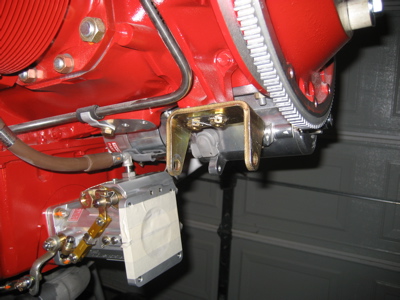
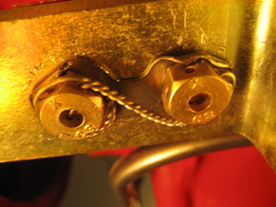
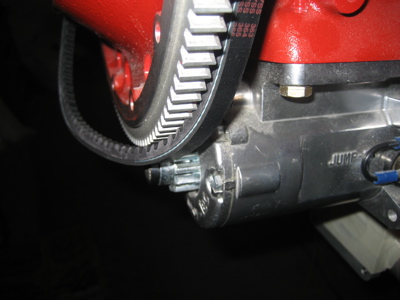
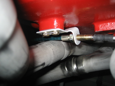
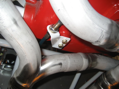
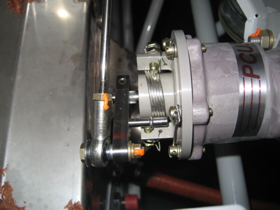
I re-safety-wired the throttle cable bracket in its new orientation on the bottom of the engine sump. As is often the case when I try to use safety wire, it took about eight tries before I managed to get it right. Sometimes it sucks to be a perfectionist cursed with limited motor skills.

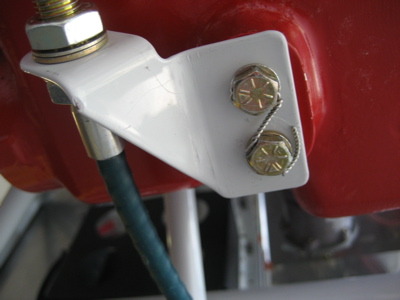
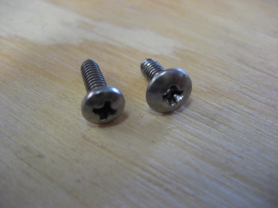
The little machine screws that come with the firewall eyeballs I'm using are so easy to strip out that you can almost ruin one just by pointing a screwdriver in its general direction. I went to the hardware store and picked up some different screws (on the left in this photo) that have a more substantial head and can actually be tightened by humans.

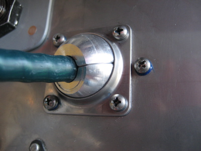
In addition to the split lockwashers under the screw heads, I used a dab of blue Loctite on the theads of each screw as I installed the firewall eyeballs for good.

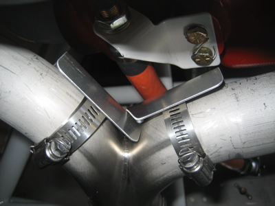
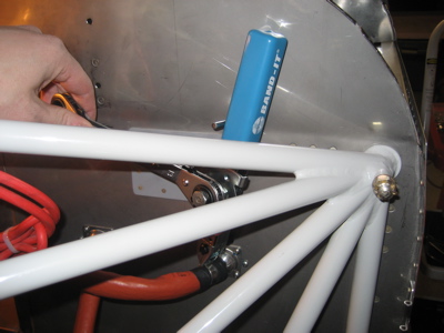
Behind the panel, I lashed the prop cable to the mixture cable with adel clamps to keep it from getting tangled up in the rudder pedals:

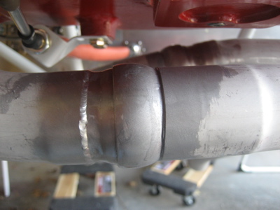
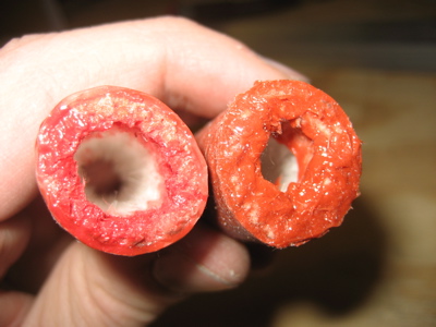
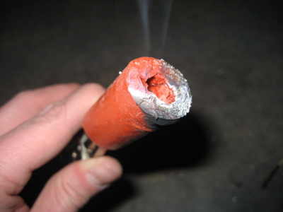
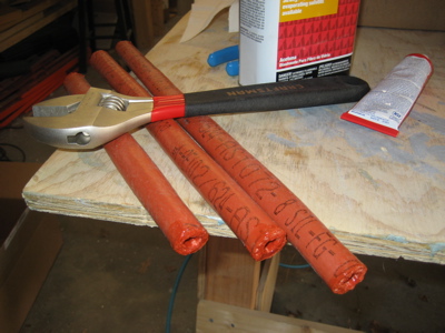
I cut lengths of firesleeve for the engine control cables and treated the ends with RTV. Technically, the prop control cable doesn't need firesleeve since it's not that close to the exhaust, but it would bother my OCD not to do them all the same way.

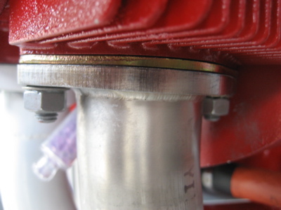
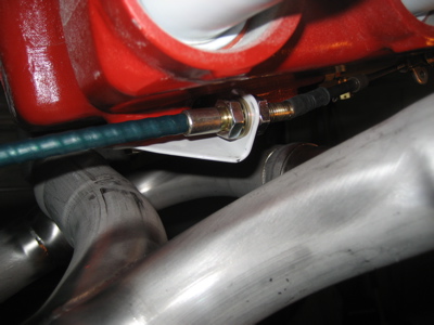
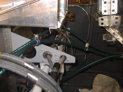
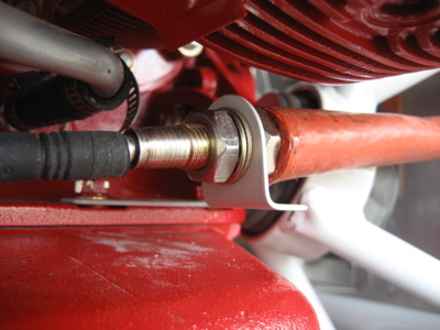
I slipped the firesleeve over the control cables and tightened the bulkhead nuts for good:

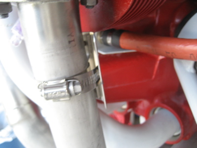
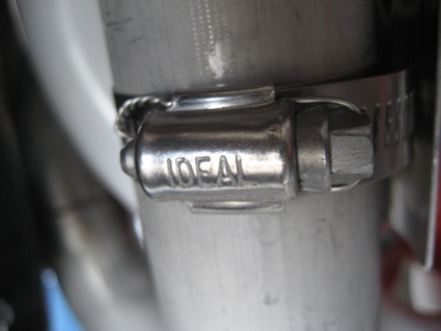
Then I finished off the ends with heatshrink tubing (a purely cosmetic touch) and firesleeve band clamps. The plans call for a simple loop of safety wire here, but I like the look of a good firesleeve clamp.

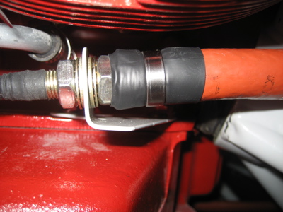
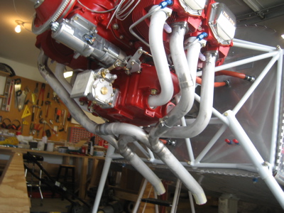
Normally you firesleeve a hose on your workbench, where you have plenty of room to use the band clamp tool. It was challenging to get all the clamps tightened, what with the engine and its various associated parts in the way, but I managed.

I tightened all the hardware in the throttle linkage for the final time and installed the required cotter pins:

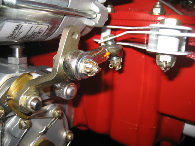
Ditto for the mixture linkage. Lots of cotter pins here. Cut my hand on at least one of them, which is pretty typical when installing cotter pins. Interestingly, the throttle side of the fuel servo uses a castellated nut and cotter pin to hold the control arm on, but the mixture shaft on the opposite side is not drilled. I used the nyloc nut that came with it (lower left corner of this image) although as a matter of principle I don't like using nylon locknuts forward of the firewall. I may eventually change it out for an all-metal locknut.

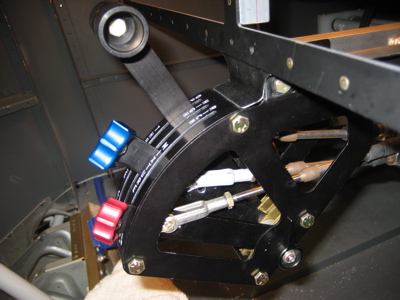
Ditto again for the prop linkage. I ended up getting about 60 degrees of travel here, which according to the manufacturer of the prop governor is plenty.

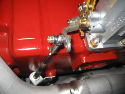
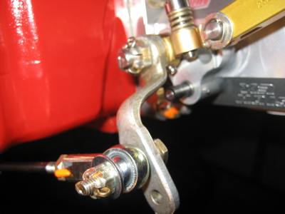
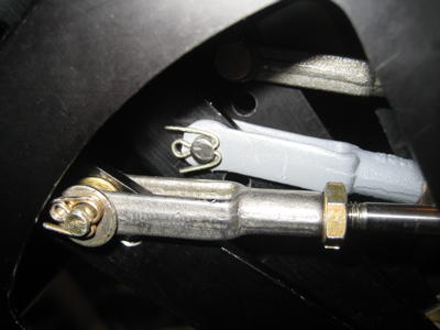
In this photo you can see a few different details of how I installed the clevises inside the throttle quadrant. First, I painted the clevis that I'd previously ground down, since I sanded off all the corrosion protection. The pins for the throttle and mixture levers are installed with their heads pointing inward, to give more clearance for the prop clevis. The outer two clevises have a 1/16" brass washer inside the fork, and a 1/32" steel washer under the cotter pin, to make sure they can't accidentally migrate inwards and foul the center lever. And finally, let me tell you that these cotter pins were a pain to install. Seriously.

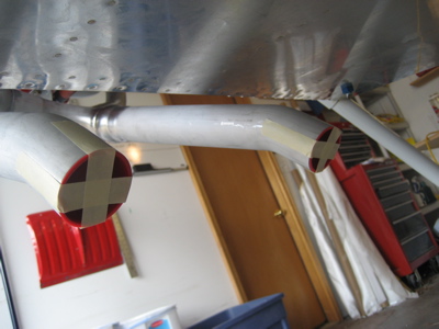
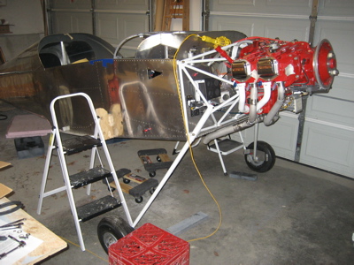
The engine controls are finished! All the way from the throttle quadrant…

…to the cables:

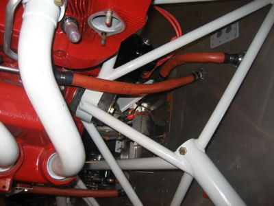
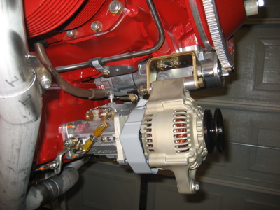
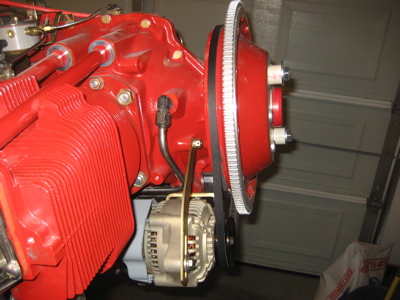
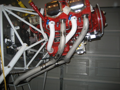
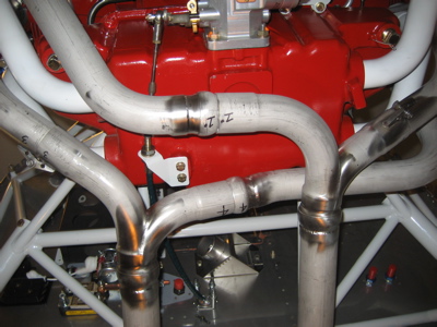
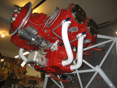
…to the engine. Awesome.

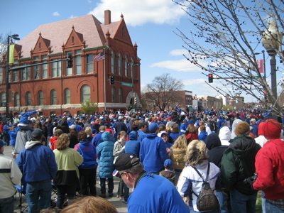
I also managed to go flying and shoot six approaches under the hood this weekend, which was fun. Now I'm legal to fly instruments for another six months.

Firesleeve testing

Sunday, April 20th, 2008

Fuel and oil hoses in the engine compartment are protected by firesleeve, which is like a piece of fire-resistant silicone tubing filled with asbestos fluff – well, probably not actual asbestos, but close enough. Because the throttle and mixture control cables come so close to the exhaust pipes, it's a good idea to firesleeve them too (firesleeve is both a noun and a verb!).

To keep the inner lining from soaking up oil and moisture, which would ruin its fire-resistant properties, it's necessary to dip the cut ends of the firesleeve in some kind of waterproof substance. There is a genuine aviation-grade "end dip" that's used by certified shops, but it sells for the outrageous price of $117.95 a quart! No way am I paying that much. So, I figured there were basically two readily available substances that could be used as a homebrew firesleeve end dip: Plasti-Dip and plain old RTV

In the interest of science, I procured a container of each and used the products within to treat the ends of a pair of two-inch lengths of firesleeve. After letting them cure overnight, I evaluated the results. The Plasti-Dip (on the left in the photo below) was more brittle than I had expected, and developed cracks when the firesleeve was flexed gently. The RTV remained slightly rubbery, as it is wont to do, and the end of its test piece remained well sealed after the flex test. Advantage: RTV.

Then I got out the matches and started burning stuff. When exposed to direct flame, the RTV became charred and began to emit a small amount of smoke, but would not ignite. This seemed like appropriate behavior for the end of a piece of firesleeve.

The Plasti-Dip sample, on the other hand, caught fire quickly and burned like a candle until I snuffed it out:

Conclusion: I will treat the ends of my firesleeve with RTV, and leave the Plasti-Dip for the occasional screwdriver handle.

Exhaust fitting

Sunday, April 13th, 2008

Since I don't post enough overview photos, here's a picture of the fuselage as it looks today. Yep, there it is.

I started today's session by getting out my Vetterman exhaust pipes and temporarily bolting them up to the engine. The welding on these pipes is really, really nice, and the fit is excellent.

What was less excellent was the way the exhaust pipes interfered with the throttle cable. After I spent all that time getting the linkage to work right, I found that the factory-supplied bracket, installed per the plans, causes the throttle cable to run right into the crossover pipe from cylinders 3 and 4. Grrrr. There needs to be at least three quarters of an inch of clearance between the cable and the hot exhaust pipe, but in this photo you can see that they are totally smooshed up against one another. No good.

After much bad language and head scratching, I figured out how to get the cable to clear the exhaust pipes by reversing the mounting bracket, thus moving the cable attach point about two inches outboard from its previous position:

Here's an end-on view, showing that the cable is now routed well clear of the exhaust pipes, through a relatively open area:

To make it all fit, I had to re-bend the bracket to make the angles work out. The geometry involved here makes it necessary for the cable to run downhill to the bracket, and then the cable's actuator rod thingy has to slope sharply upwards towards the fuel injector servo. Luckily the cable end is designed to accommodate a certain range of motion.

The linkage angles inward towards the throttle arm, where it now attaches on the outboard side with a shorter bolt. Good thing I used an offset arm here.

Here's a view looking up from the floor. With the throttle quadrant hooked up inside the fuselage, there's just barely enough travel to hit the wide-open and idle stops. I think there's actually less margin than before, if that's possible, but it does work. The cable actually has pretty good clearance from the exhaust pipes, too – about an inch, which is way more than was physically possible with the other bracket arrangement.

What a mess. The combination of horizontal induction and throttle quadrant is an exercise in frustration. And speaking of messes, this is what happens when you fiddle with control cables for multiple weeks without putting your tools and parts away – it took me half the afternoon to clean this up:

We also went to the huge parade they held downtown to celebrate the big sports victory.

My views on sporting events are well known, but it was still fun.