Archive for August, 2009

More wiring

Sunday, August 30th, 2009

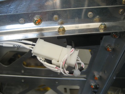
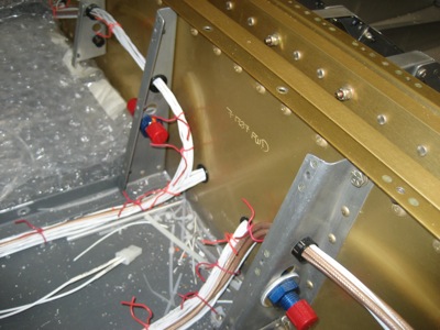
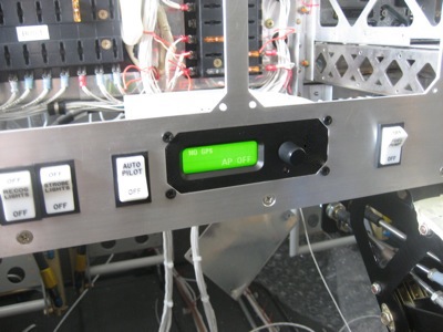
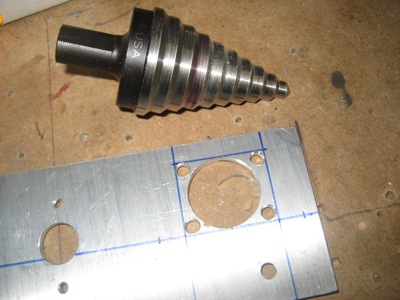
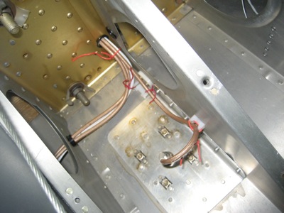
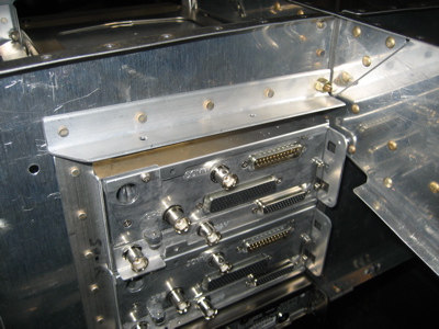
I ran wires and installed connectors for the rudder trim switch (lower center) and its associated speed control (upper center).

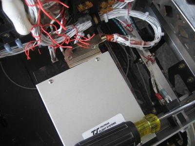
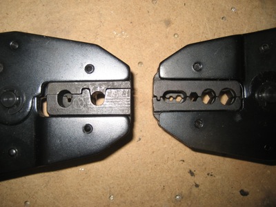
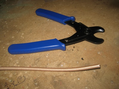
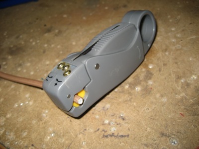
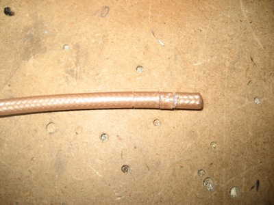
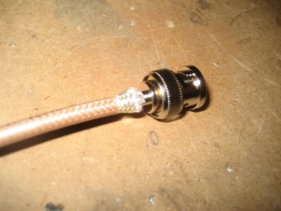
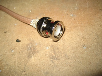
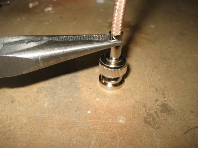
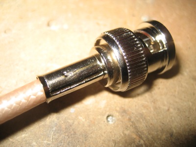
I used some miniature connectors for the 26-gauge wire on the Ray Allen trim components. I used the size of pins and sockets that are rated for 22-26 gauge wires, and doubled the wire strands back on themselves before crimping… worked great. I also bundled all the small wires together with a piece of double-wall heatshrink to provide sort of a strain relief.

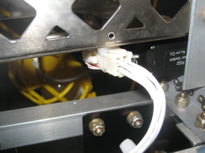
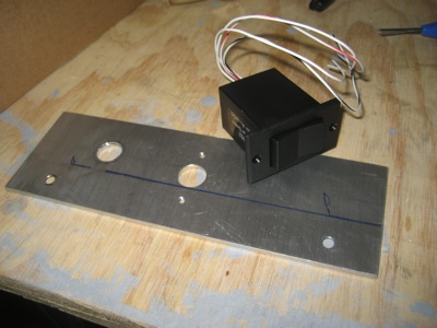
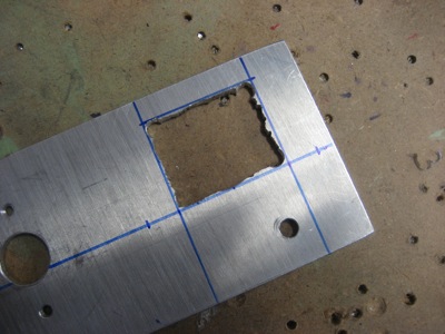
Same thing on the rudder trim switch side. Also: Dear Ray Allen company, what's up with you guys and 26-gauge wire? Would it kill you to use something slightly heavier than can be used with normal tools and connectors?

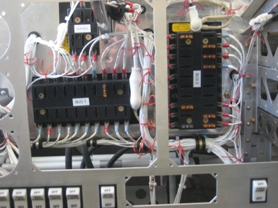
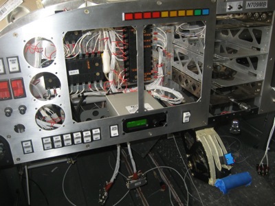
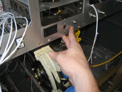
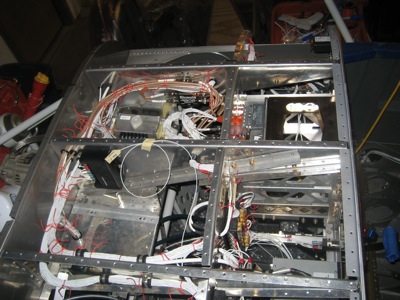
Since I have a habit of only posting extreme closeups, here's a few overview pictures to show how the wiring is progressing. First, a wide shot of the whole panel. The glare is due to the garage door being open to let the extremely nice weather in.

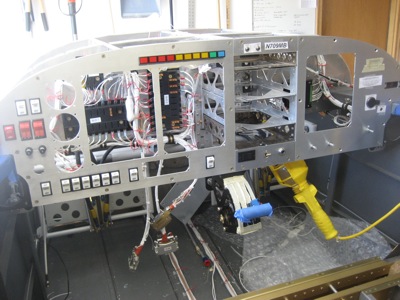
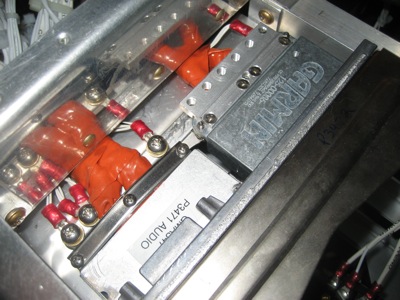
Big fat bundles of wires surround the main bus fuse blocks, but it's all relatively tidy.

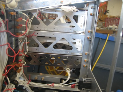
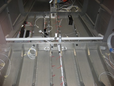
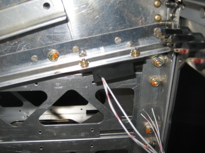
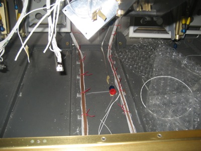
Wire bundles running back through the spar and out to the wings. I'm starting to run out of room in the snap bushings that go through the F-704 center section. You only get a total of four half-inch diameter holes to pass all your wiring through, which may be enough for a simple VFR airplane but is totally inadequate for an intergalactic spaceship like I'm building. I know some people have drilled extra wiring holes here, but since the spar is so critical I think I will wait to get blessing from the factory before I go poking any more holes in it.

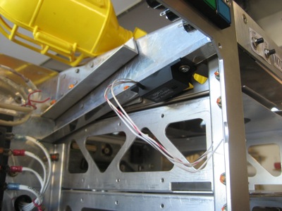
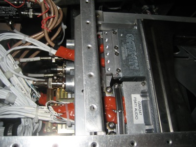
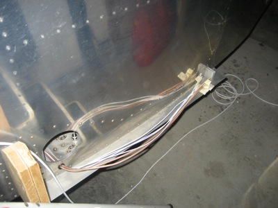
Looking aft towards the tail… I do have two extra snap bushings in the lower F-705 bulkhead web, which were approved by the factory. I had originally intended those to be used for running wires to the ELT and strobe power supply, but now I'm thinking of moving the ELT somewhere else (yes, again) and switching to LED strobes, which don't need a power supply. However, I have enough other wires and antenna cables that need to get back to the tailcone that I'll probably end up using these for other purposes. You can see in this photo I've already started running trim wires for the passenger stick through one of them.

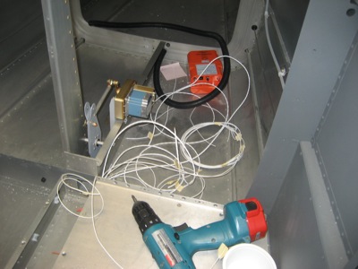
Big coils of wire are starting to pile up aft of the baggage bulkhead, in preparation for some future date when I get around to crawling back into the aft fuselage to run wires to the empennage and aft-mounted antennas. Not to mention retrieving whatever else has fallen in there.

Autopilot wiring

Saturday, August 29th, 2009

I ran wires for the autopilot autopilot and got it powered on and talking. Lucky for me it fits perfectly in the panel, so I guess my CAD drawing of the cutout was accurate.

Here's a closer view. Notice that my panel has an on/off switch for the autopilot, so if it tries to kill me I can return the favor.

The autopilot is too deep to use a standard D-sub connector (it hits the subpanel) but I was able to make it work by using an expensive right-angle D-sub backshell. It was pretty dicey to get the two halves of the backshell clamped together and the thumbscrews inserted without pinching any wires.

All the fuselage wiring for the autopilot is in, but I haven't installed the connector for the pitch servo or the wing root disconnect for the roll servo yet. I'll do that later.

Rudder trim switch

Sunday, August 23rd, 2009

I've been thinking for a while that I'd eventually like to add rudder trim to this airplane, similar to what other builders have done. I may not actually get around to putting a servo in the rudder any time soon, but if I at least install a switch in the panel and run wires back to the tail it will be a lot easier to retrofit later. If I decide to fly the airplane before installing rudder trim, I'll just placard the switch "inop".

I had a Ray Allen rocker switch left over from a previous project, so I located it and dusted it off. There's a spot just below the radio stack, next to the flap switch, that's just about perfect for it.

I measured and marked cut lines, then used a unibit to hog out most of the material:

Then I used a hacksaw blade (held with leather gloves) to make a roughly square hole:

Then I filed away at the edges until the switch fit through the hole. It's not the kind of perfect cutout that I'd have had if I'd thought to include it when the panel was being CNC cut, but the switch bezel hides all that.

Test fitting in the panel:

To allow me to adjust the sensitivity of the rudder trim, I attached a Ray Allen servo speed control to the lower flange of the center subpanel rib.

Here's another view. I'm sure this thing is nothing but an LM317 and a trimpot, but it's easier to buy one of these than to roll my own.

Anyway, at least I can run all the wiring now and make the airplane ready for a future upgrade. Maybe some winter when it's too cold to fly I'll build a new rudder with a fancy trim tab… it would be nice to have a choice between building and flying! The airplane that I'm sort-of partners in has been down for maintenance since March, and of course the RV-7 is still in pieces in my garage.

Wiring, coax, antennas

Sunday, August 16th, 2009

I found the screws and lockwashers for the Garmin connector backshells, so I was able to get the audio panel connectors installed:

I'm not really happy with the way the wire bundles are pressed up against the reinforcing angle along the top of the radio stack. The wires are wrapped in silicone tape, and they're not free to move around very much, but then again that corner is sharp. I may drill out those rivets and replace the extruded angle with something that has a rounded edge instead. Once the top skin is riveted on, it's going to be very tough to get to these wires, so I want to eliminate any potential sources of future trouble.

Meanwhile, I installed an antenna splitter (aka quadraplexer) on the subpanel rib close to the back of the radio stack. This is an expensive little doodad that divides the output from the single antenna into separate nav and glideslope inputs for each 430.

I ran coax for both comm antennas, the nav antenna, and the marker beacon antenna, plus four short lengths from the radios to the nav antenna splitter. These wire bundles get big in a hurry when you start adding multiple parallel strands of RG-400.

Aerial view of the panel wiring so far:

Comm 1, nav, and marker antenna coax go down the left side of the floor, and comm 2 is the right. Not installed yet are the coax runs for the GPS (x3), transponder, and XM antennas. I'm waiting to run those until I get all the antennas installed in the aft fuselage, and until I have a solid plan for wire routing to avoid using up all the space in my spar bushings before I'm done running the small-gauge wires.

At the wing roots, the comm antenna coax is tied to the rib to keep it out of the way of the aileron pushrods, and the nav and marker antenna cables exit the fuselage through a snap bushing.

Eventually there'll be connectors for the wing wiring here – meanwhile I'm just leaving the fuselage wires extra long.

House chores on Sunday, no airplane work…

How to crimp BNC connectors

Monday, August 10th, 2009

As I was making antenna cables, I thought it would be useful to show my method for crimping BNC connectors. The usual disclaimer applies: I am not an expert, I'm just showing you what I do.

I get my connectors from Aircraft Spruce, although you can find them just about anywhere. These particular ones are made by Amphenol and sell for about three bucks apiece.

Here's what comes in the bag… connector body, ferrule, and center pin:

One of the secrets is to use the right kind of coax stripper. The tool I use has three spring-loaded blades in it (kind of like my razor, I suppose). If you see one at your local hardware emporium, be sure to check the model number – all the ones I found in the local stores were configured for television coax cable. For stripping the RG-58/RG-400 coax we use in airplanes, the model 1255 is the one you want. I couldn't find one locally so I had to mail-order it, but it was comparatively cheap.

Since I'm a tool junkie, I experimented with different kinds of crimping tools. On the top is the "economy" racheting crimper sold by B&C for $40. On the bottom is an Eclipse frame with a set of RG-58/RG-400 BNC connector dies in it – cost for this setup is about $25 for the frame and $15 for the die, so it's basically a wash (prices are from Terminal Town where I bought mine). The dies on the economy tool are removable, and might actually be interchangeable with the Eclipse, but I haven't tried.

Here's a closeup of the crimp dies on both tools. On the left are the RG-58/RG-400 dies in the Eclipse tool, and you can see that there is just one crimp position for the pin and one for the ferrule. On the right is the economy tool, which can crimp multiple connector sizes. Either one works, although I find myself mostly using the Eclipse tool since I'm always crimping the same size of connector and it's impossible to get the pin in the wrong hole if you only have one choice. The other reason I prefer the Eclipse is that it makes a cleaner crimp on the pin… with the economy tool, the pin seems to get squashed flat a little more, so it's sometimes harder to get seated.

To cut the coax to length, be sure to use a real cable cutter, not a pair of dykes. The cable cutter has curved jaws that won't squash the coax insulation nearly as much, and it's cheap. These should be available wherever electrician's supplies are sold.

To strip the cable, clamp the stripper on the cut end using the illustration on the tool as a guide. It takes several practice runs to get the height-changing setscrews adjusted to give the proper depth of cut, so don't be afraid to use up a foot or two of coax getting your tool configured. To use the tool, use your finger to twirl it clockwise around the end of the cable (if oriented as it is in this picture) four times, then one turn counterclockwise.

If the blades are set correctly, you'll end up with (from left to right) a shallow cut through the outer insulation, a deeper cut through the braided shield, and a third cut that goes through the inner insulation.

With gentle persuasion, the cut segments should come right off and leave you looking at the untouched material underneath the cut. Take a minute to closely examine the cable for stray shield strands that might float around and bridge your two conductors together. You can leave the center conductor slightly long, since you'll probably be trimming it a bit anyway.

Slide the pin over the exposed center conductor. You want the base of the pin to be almost, but not quite, touching the white insulation. Trim the center conductor a bit at a time until it's the right length.

Squash the base of the pin with your crimper, and give it a tug to make sure it's secure.

Now slide the ferrule over the cable. If you're going to label it, now is also the time to slide on your heatshrink label.

Push the connector body down over the end of the cable until you feel a click as the pin is seated. The knurled bit on the back will dig under the braided shield. If you encounter strong resistance, can't get the pin all the way in, or don't feel the click, the most likely problem is that the crimper has deformed your pin enough to make it hang up in the connector body (see above).

When properly seated, the end of the pin should be flush with the end of the plastic insert inside the connector:

Without unseating the center pin, slide the ferrule down over the exposed shield. With the neato coax stripper I use, you should find that the shield has been trimmed to the perfect length and you don't have any stray shield strands poking out.

Now crimp the ferrule, and you're done.

I like to do a quick continuity check just to make sure the center pin isn't shorted to the shield anywhere. Antennas don't work very well with a shorted cable.