I know, no updates for quite a while… not only has there been the usual round of holidays, travel, garage coldness, and winter illness, but also the following fact: even though I've been doing a lot, I don't feel like I've gotten anything done in a while. That is, in the sense of (adjective) completed; finished; through. The engine baffles and air inlet duct are each a series of interlocking mysteries, and I haven't completely cracked either one. Still, I have a bunch of pictures on my camera, so I guess I should post them so you can see I've been making some amount of progress.
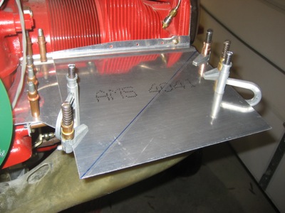
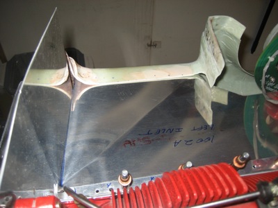
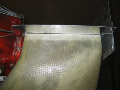
I worked on fitting the left inlet ramp to the cowl, starting by drawing a line from the outboard corner of the baffle to the point where it touches the lower cowl:
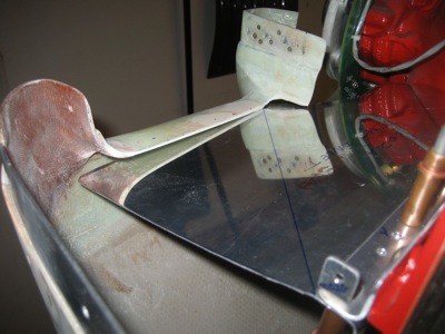
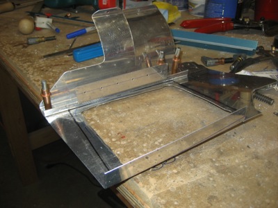
I put an upwards bend along the line, a little at a time with plenty of trial and error fitting in between:
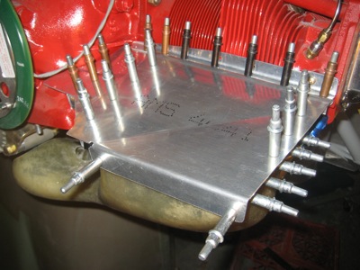
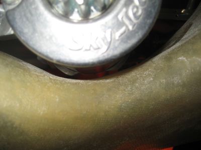
With the correct amount of bend in the middle, the inlet ramp now touches the lower cowl all along its length. Well, almost touches – I want an even 1/16" gap between the two parts to accommodate the rubber airseal that will go there later on. You can also see I've trimmed the outboard edge to bring the #2 cylinder baffle in line with the cowl.
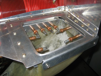
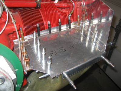
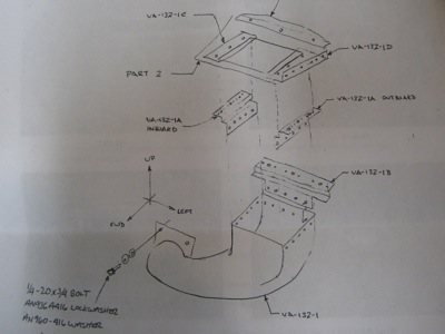
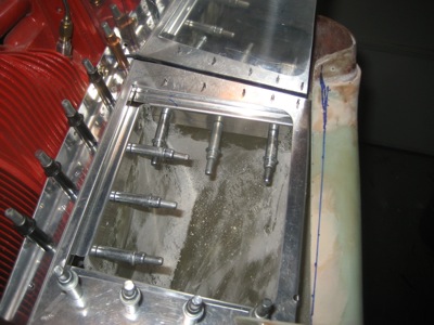
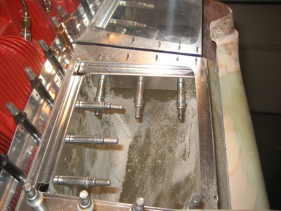
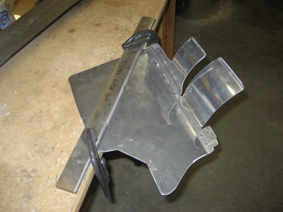
I cut this baffle attach plate to fit, and mounted it on the engine case:
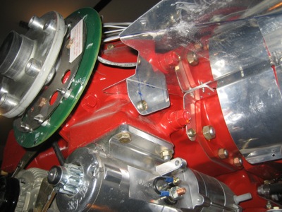
Drilled and clecoed the associated angle piece:
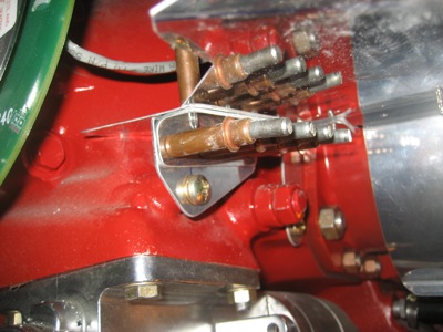
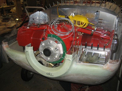
Here's an end-on view showing how the various parts are arranged. This locks in the angle of the left-side inlet ramp.

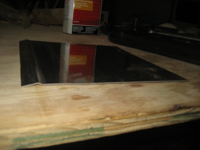
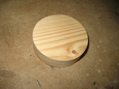
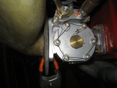
Per the plans, I cut a round plug out of some scrap wood. It kind of looks like Jupiter. Or maybe something else.
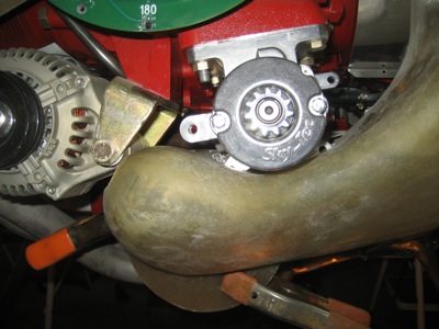
Using thin packing tape, I attached it to the throat of the fuel injector metering servo:
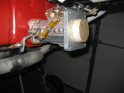
The plug centers the engine air duct on the engine air inlet while it's clamped in place for fitting.
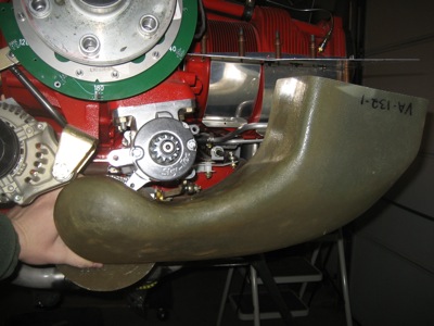
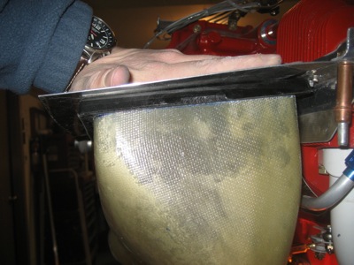
This is how the air duct fit straight out of the box. Lots of trimming and grinding awaits.
It took lots of hours of tediously iterative work to improve the fit, and I didn't take many pictures along the way. Here's one I found on my camera that documents my use of some special-purpose tape that's specifically designed for taping ducts.
You can't control the fore-and-aft position of the duct on the baffle, but you can adjust the side-to-side fit by grinding away obstructions and rotating the duct around the wood plug on the fuel servo. It's made extra challenging by all the stuff that's in the way, and the fact that the inlet ramp has a kink in it.
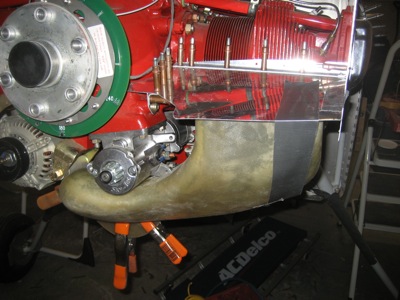
I stopped trimming once the duct was centered side-to-side on the inlet ramp and the fit was pretty good all around. It will get trimmed back later to allow space for the air filter.
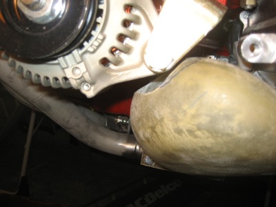
I had to grind off quite a bit of material to fit the duct around the alternator – in fact I'll have to open up this hole later on to provide some extra clearance.
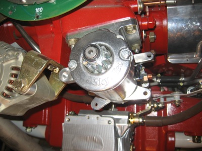
The starter also has two protruding lugs on it, just visible in this picture, that hit the duct. I ground away more fiberglass to make it fit.
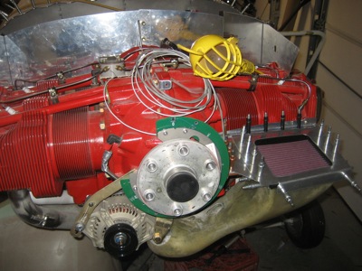
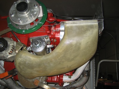
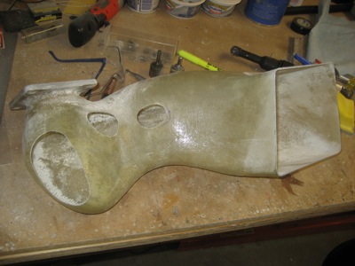
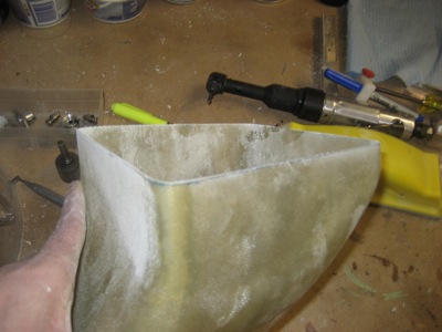
Skipping ahead a bit, here's what it looks like after being fitted. The extra holes will be glassed over once I'm done with everything else, thus making it a custom-fit part.
After looking at the documentation for the starter, I discovered that it's permissible to cut off the unused lugs on the starter as long as you don't cut into the case itself. Good news, since I was worried about how much the airflow in the duct would be constricted if I had to use fiberglass to mold in "dimples" for clearance.
So, I removed the starter from the airplane in order to perform some elective surgery:
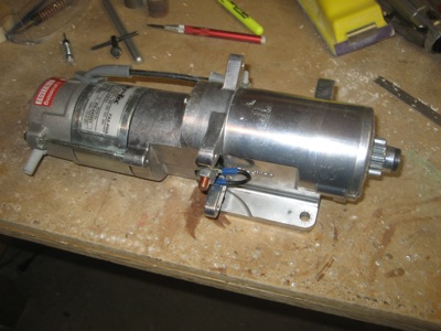
Hah, not so tough now, are you?
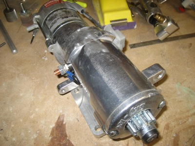
He was no match for Señor Hacksaw and Mister Grindy:
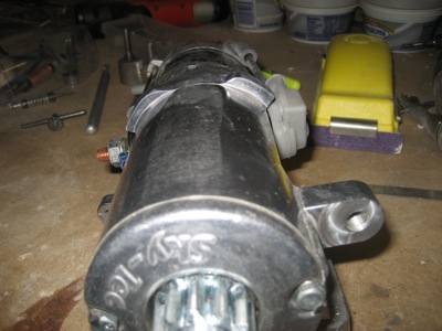
Not a great picture, but you can sort of see that the starter lugs no longer intersect the surface of the duct. Next time I get out the glass and glue, I'll patch these two holes. That's the one nice thing about fiberglass – especially for nonstructural applications, you can usually put back on whatever you accidentally took off.
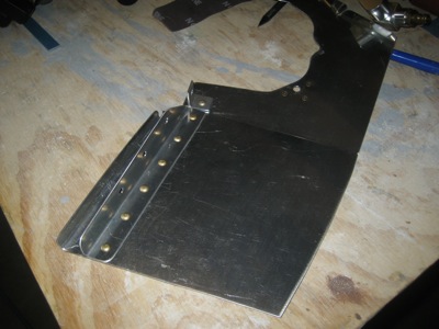
I marked a line on the duct, 3/8" from the underside of the inlet ramp:
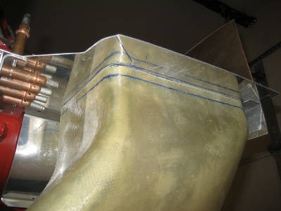
Then I cut and sanded to the line. You can see the odd shape required to match the bottom of the bent-up baffle.
I drilled holes to mount the duct to the fuel servo, which was harder than it ought to be due to the lack of room to work in. Then I trimmed the excess material off the duct flange.
Bolted up for a test fit. Two of these bolts are very difficult to put in – too bad this piece still has to go on and come back off many more times.
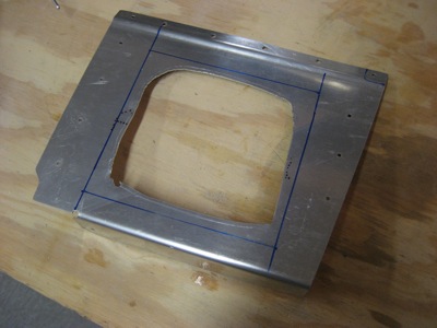
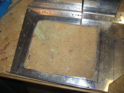
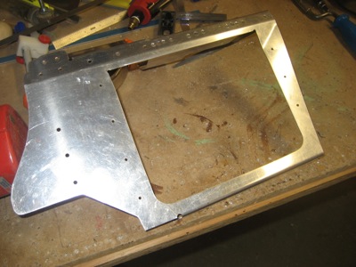
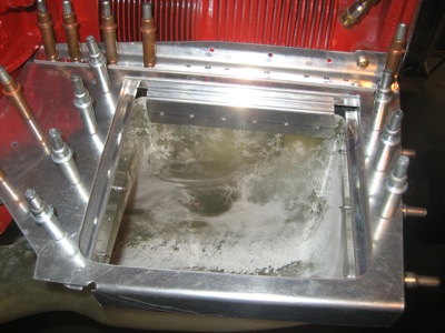
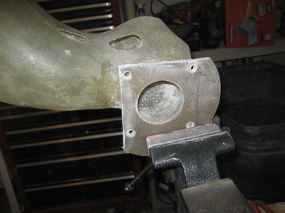
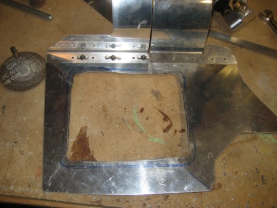
I traced the outline of the duct onto the inlet ramp baffle. The plans say to cut to the line, but I'm not sure I trust them on this just yet.
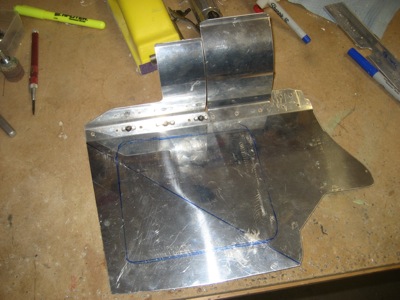
Instead, I used the air nibbler to rough cut a hole about a half inch back from the line. That will give me room to adjust the hole size once I figure out the air filter mounting scheme.
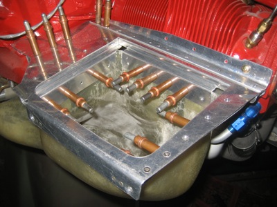
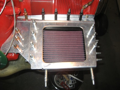
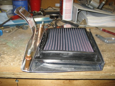
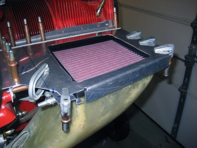
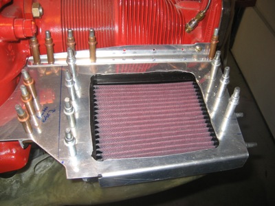
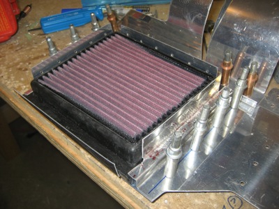
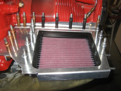
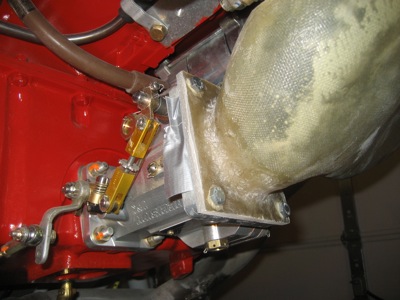
Placing the baffle, filter, and duct on the engine for a trial fit:
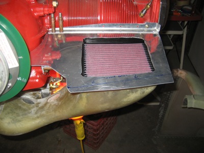
At least the duct/filter/baffle intersection is a good fit. But, there's not much room between the filter and the cylinder, or ahead of the filter – especially once the air ramp gets trimmed to its final length. I'm going to have lots of fitment and edge distance problems here.
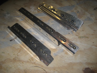
I made these filter brackets by following the dimensions in the plans. Silly me! Maybe I'll be able to use them as templates for how not to make the correct brackets – once the replacement material arrives, that is. Argh.
Really, the secret to the baffles and air duct is to use the plans only enough to understand the desired outcome, and then improvise the actual construction as necessary. Come to think of it, I think I saw this in a movie once.

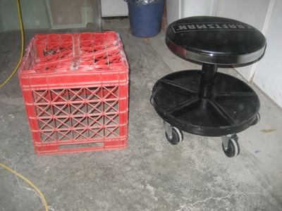
Oh, I also finally broke down and bought myself a real work stool to sit on while I'm messing with the engine. For the last fifteen years I've used this milk crate as a chair while doing who knows how many projects, and I was starting to get really tired of it. Judging from its appearance, I'd say the feeling is probably mutual.