Archive for March, 2011

The old paper clip trick

Sunday, March 13th, 2011

Once the baffles are roughly trimmed far enough to generally fit under the top cowl, you then have to trim them further so you get a nice even gap all the way around the engine. I used the "old paper clip trick" to figure out what to trim and what to keep. I didn't invent this method, but here's how it works…

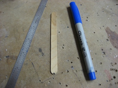
You start by putting a whole bunch of paper clips on top of the baffles. The jumbo size seems to work best.

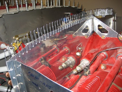
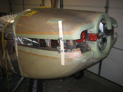
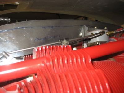
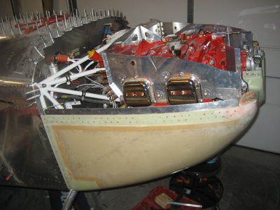
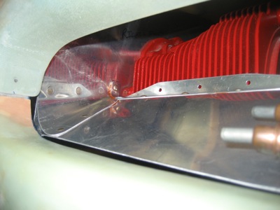
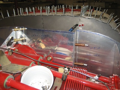
Then, very carefully put the top cowl on, and push it down onto the paper clips. Here's a view of what's happening inside, looking in from the oil filler door:

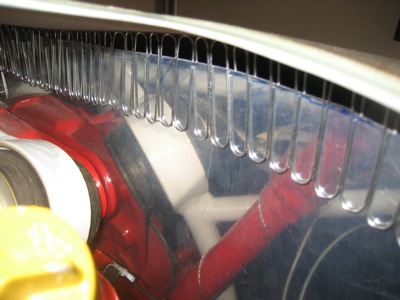
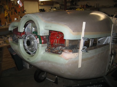
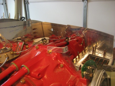
This is another view looking aft from the spinner opening:

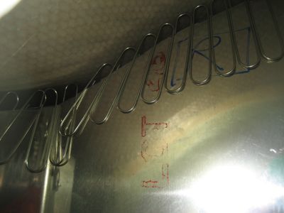
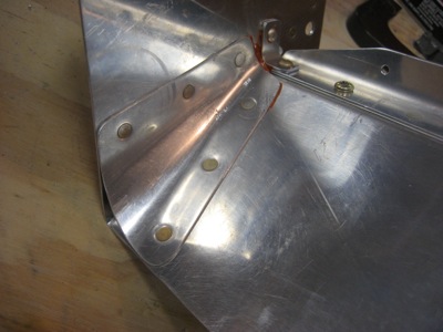
Then you carefully remove the cowl, and if you're lucky you're left with an impression of the inside face:

Mark a line the desired distance down from the top of the paper clips – without bumping them out of position! – and proceed to trim, file, and deburr.

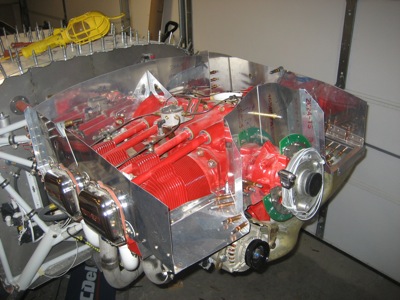
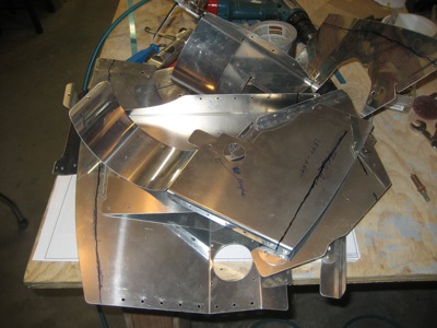
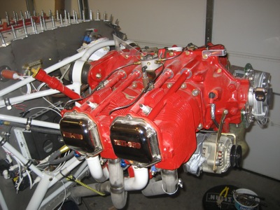
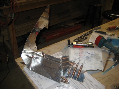
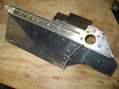
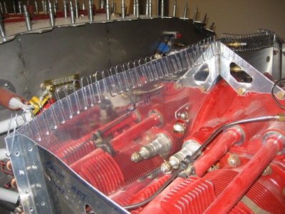
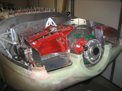
Then, repeat a dozen more times! Seriously, I did this for hours, tweaking the fit a little more each time. The baffles came off and went back on many many times, which I didn't bother to take pictures of. But the finished product looks something like this:

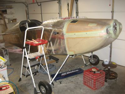
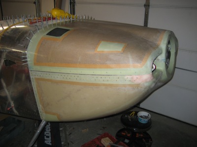
Not a very interesting picture, I know. So here's a shot of the whole airplane with the cowl on, which is more fun to look at:

Baffle trimming

Monday, March 7th, 2011

It's finally time to start fitting the baffles to the top cowl. The upright baffle parts all start life being extra-tall, and then they get trimmed down so they end just short of the top cowl. You don't want too small of a gap between the fiberglass cowl and sheet metal, which could cause the shaking engine to damage the cowl; you also don't want too large a gap because it prevents the rubber air seal material from doing its job.

But, since the cowl isn't transparent, how do you know where to trim without a lot of tedious trial and error? I used a method suggested by someone else, which begins by using wood strips to elevate the top cowl some known distance above its usual position:

After making sure the gap is even at each corner, you then reach through the gap to trace the contour of the top cowl onto the baffles.

It just happened to work out that a popsicle stick is just the right length to give me a 3/8" offset from the inside cowl contour. I notched the end to locate the tip of a sharpie, then used this contraption to draw a line on the baffles inside the cowl.

This is a picture looking in one of the cowl inlets, showing the line I traced. This worked pretty well and wasn't too difficult, other than requiring some painful contortions to get the pen onto every corner of the baffles while working in a limited space.

After removing the top cowl, I retraced the wobbly line so I could see it while cutting:

Then I removed all the baffle parts (quite a chore).

This is the first time in quite a while that the engine has been baffle-less:

The bandsaw made quick work of the initial trim cuts. I stayed outside the line, since there is some error inherent in this process, and I didn't want to cut off too much too quickly.

Everything goes back on for fitting, for the nth time:

After only one cut, it almost fits! Still a little trimming left to do in the aft corners, where I had a hard time making sharpie marks.

Here's a view into the right inlet, with the top cowl in place. I'll have to trim the cylinder baffles down a lot further once I glue the upper inlet ducts in place, but that will come later. For now, I'm glad I haven't attached them yet, since they would just be in the way.

Next: Yet more trimming…

Cylinder 1 baffle

Saturday, March 5th, 2011

It's relatively easy to remove and replace the engine baffles when they're still individual pieces clecoed together; it's tougher to do it when the various pieces are assembled into big unwieldy shapes. I am trying to design for future maintenance as much as possible, so I am trying to ensure that the baffles can all be removed without drilling out any rivets. In certain places this might require using screws where rivets are specified – we shall see. I know that the finished baffles are all going to have come off at least once before the airplane flies, since there is already at least one airworthiness directive on the cylinders that will need to be addressed.

With that in mind, I tested my ability to remove the baffles attached to the #1 cylinder as a complete unit – cylinder head baffle, inlet ramp, and crankcase baffle all clecoed together. With the flywheel removed, it's just possible to twist and turn it enough to get it off the engine and put it back on. So, all the parts you see here will eventually be riveted together as a single assembly.

I riveted the stiffener angle and the various brackets to the inlet ramp. Some rivets could be squeezed, and some had to be driven. Surprisingly, considering I haven't used the rivet gun in ages, none of them look too bad. Note the use of flush rivets between the three screws that will eventually attach an air dam in front of the #1 cylinder.

Then I riveted the cylinder baffle and corner gusset to the inlet ramp With careful planning, these rivets can all be squeezed if you do it in the right order. You can see where I used some red RTV between the mating parts to fill some gaps that would otherwise be air leaks.

I'll wait to rivet the crankcase baffle until I finish fitting the baffles for good, since not having it permanently attached makes it a lot easier to remove and reinstall the baffles… and unfortunately there's still a lot more of that to come.