Archive for December, 2013

Magneto P-lead / RPM sensor / oil temp probe

Sunday, December 29th, 2013

Three projects in one post today, for reasons that will become clear…

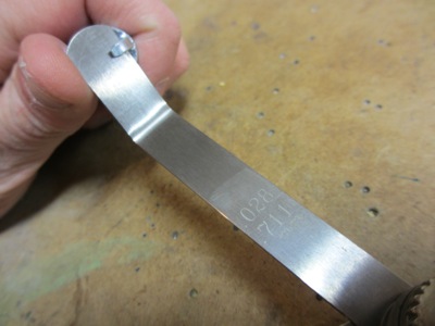
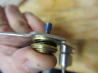
First, I fabricated the business end of the magneto P-lead. This connects to a switch in the cockpit that operates in reverse of the normal fashion. When the switch is open, the magneto can operate and generate its own sparks. When the switch is closed, the magneto is grounded and can't fire. For historical reasons unknown to me, the terminals on the magneto to which you connect this pair of wires are called "GND" and "P", hence "P-lead".

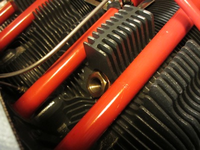
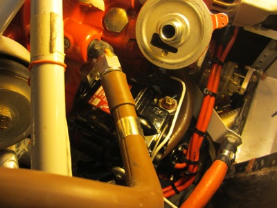
The open hole partially visible in the center of this image is where the oil temperature sensor goes. The hex-shaped thing below it is the exterior portion of the Vernatherm, which is a fancy trade name for "thermostat". The stuff at the top of this picture is where the oil filter threads on. Sorry for the terrible photo, this area is really close to the firewall so I can barely get my camera back there, let alone see it when I'm trying to work on it.

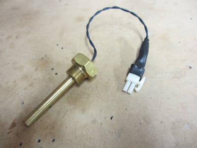
This is what the oil temp probe looks like. I crimped on a connector so I can replace it more easily in the future if I have to.

Oil temp probe installed with a new AN900 copper crush gasket. Crush gaskets are kind of interesting since you tighten them by turning to a specified angle rather than using a torque wrench. Since the hole uses a 5/8-18 thread, this gets tightened to 135° beyond finger-tight.

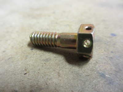
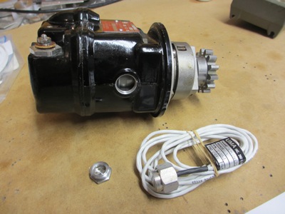
To install the RPM sender on the magneto, I had to remove the mag from the engine. Ugh! Wish I'd thought ahead a little more. Oh well.

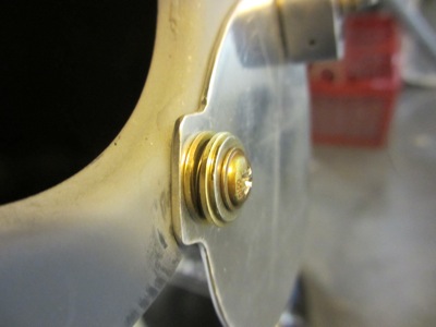
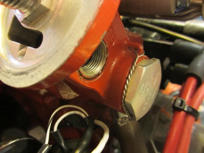
The RPM sender threads into an unused vent hole on the mag, which is usually capped with a hex-shaped plug.

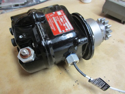
RPM sender installed in mag, using blue loctite and tightened to the specified torque. The P-lead and ground screw hole are visible at left.

Mag reinstalled… I used the timing pin and attempted to get it timed properly, although I will revisit the timing again for both the magneto and P-mag at some point in the future.

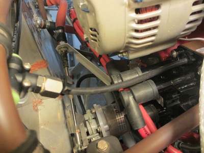
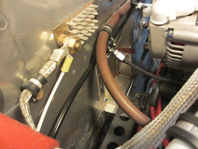
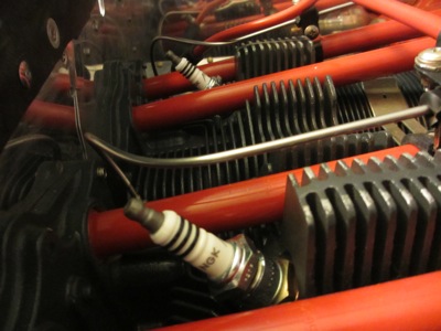
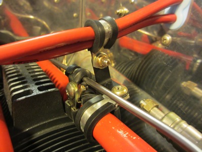
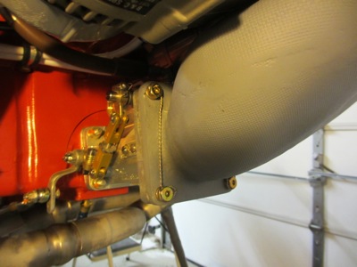
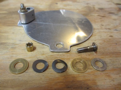
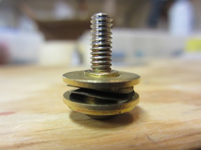
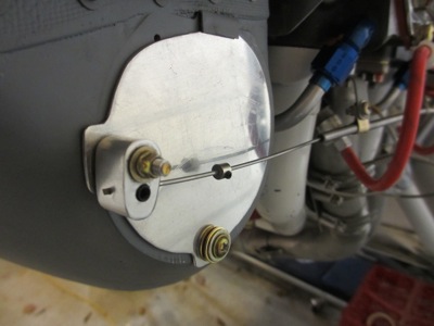
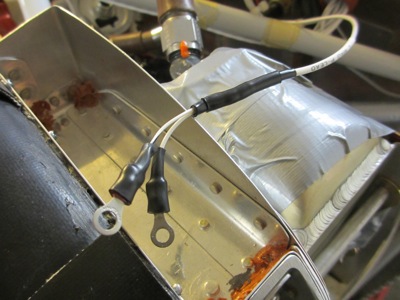
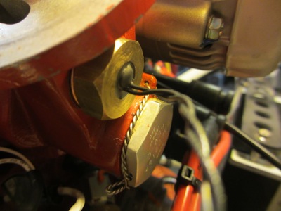
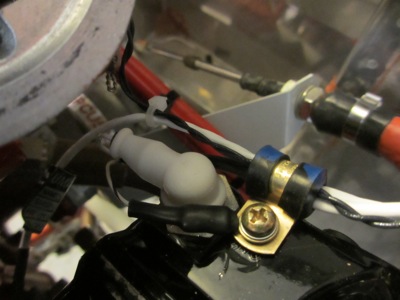
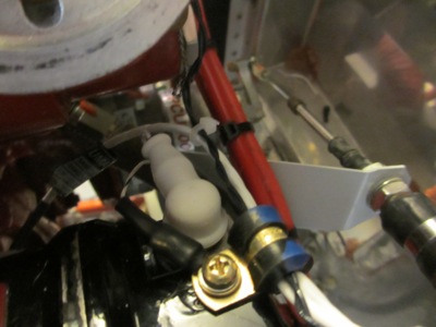
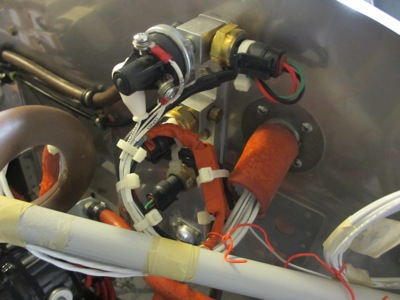
Now here is why I'm covering three otherwise unrelated wiring projects in the same post. All of these wires – P-lead, oil temp, and RPM – pass through the same area on the back of the engine, and all of them need to be supported so they don't vibrate and eventually break. The most convenient place to anchor these wires is actually the hole for the P-lead ground screw itself.

So what you're looking at here is the back of the magneto, with an adel clamp affixed to the hole that normally just gets a ground terminal; the ring terminal for the ground lead is between the screw head and the clamp. The other P-lead conductor loops around and attaches to the magneto "P" terminal, hidden under a rubber boot. Meanwhile, the wires for the oil temperature probe and the RPM sender pass through from left to right and are restrained by the clamp.

Again, sorry for the photo quality… this area is hard to see, hard to work on, and hard to photograph.

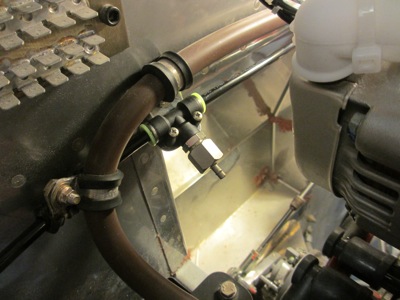
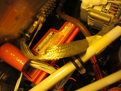
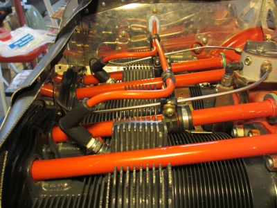
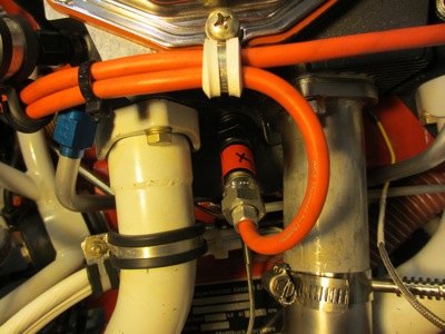
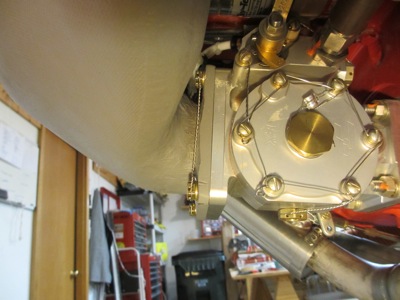
Moving upwards, the wire bundle loops around an oil hose and then attaches to the engine mount. Where there is currently masking tape holding things temporarily, I will eventually put a pair of adel clamps to grab onto this wire bundle. As with the bus current sensors, I used silicone tape around the connector for the oil temp sensor to keep water out.

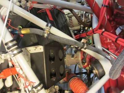
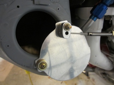
Same area, this time with the oil filter installed:

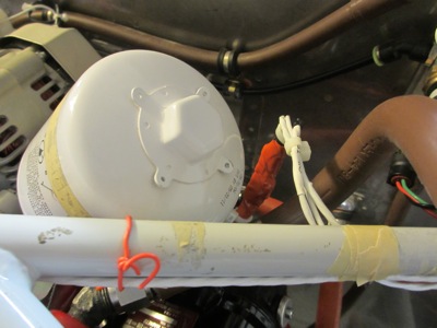
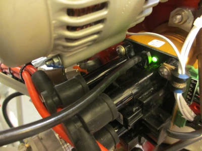
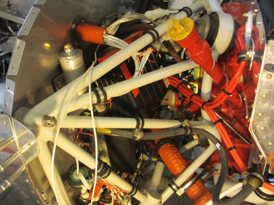
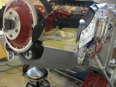
Another glob of silicone tape to protect the connector for the RPM sensor, and then all three sets of wires pass through the firewall:

By the way, I did not think of this clever wiring trick myself – I got it from this VAF post.

P-mag manifold pressure hose / battery fit check

Sunday, December 15th, 2013

The P-mag requires a manifold pressure connection in order to control its timing advance. I had previously located a tee fitting in a convenient location, but I never finished it since I didn't have the right fittings on hand. Time to check that off the list, so here's a combination of fittings that allows me to tap off the 1/4" OD plastic hose with a 1/8" ID rubber line to the P-mag:

Here it is mounted on its little bracket. Note the pair of adel clamps on the left side of the image – they will become relevant later.

Manifold pressure line connected to the P-mag. I used the stuff that came with the P-mag, but it seems like it might just be regular old vacuum hose from the auto store.

Since I was working with the P-mag, I plugged in the power supply and verified that it gets power when the master switch is on (note green LED). I also set the crankshaft to TDC and blew in the tube to set the initial ignition timing, although I will probably adjust it again before I try to start the engine.

At some point while I was messing around in this area of the firewall, I started thinking, "hmm, there sure are a lot of things running through this area, wouldn't it suck if it turned out to be impossible to install and remove the battery now?" So I dug the battery out of the basement and tried a test fit. It's really tight with all that stuff in there! I had to push the ignition wires, ground strap, and oil pressure hose out of the way…

Almost thereā€¦ it's like getting a battery-sized square peg through a series of triangular and oblong holes…

Home free now! From here it just drops straight down into its tray. Of course then I had to reverse directions and remove the battery again, which was equally painful.

Here's that manifold pressure plumbing again. I had to remove the adel clamps in order to be able to flex the oil pressure hose out of the way of the battery. Subsequently I decided to just leave them off – if these two lines turn out to rub together, I'll fix it with a dab of RTV.

Kids, do yourself a favor and think about battery replacement when you're locating stuff on the firewall. I didn't give it enough forethought and I almost screwed myself. Lesson learned.

Top spark plugs

Saturday, December 14th, 2013

Today I installed the top spark plugs on all four cylinders. For posterity, here's a photo of the box of plugs I used… NGK BR8EIX iridium plugs, as recommended in the P-Mag install manual. The 6747 part number has solid terminals, not the two-piece screw-on variety, which is preferred for this application.

The back of the box has a "not for airplanes" pictogram. That's encouraging.

The engine came with a set of cheap Denso copper plugs. I'm sure these would work fine, but I thought I'd go with iridium plugs based on past experience with an airplane that had a car engine in it. Also I've been really impressed with how long the OEM iridium plugs in my car have been going, with no appreciable wear.

View of the old and new plugs showing the difference between the two types of electrode.

You're not supposed to gap iridium plugs by hand, but I did check the plug gaps just to make sure they were manufactured correctly. The manual recommends a gap of between 0.030" and 0.035"… all four of my plugs were 0.028", which I'll consider close enough.

To use auto plugs in an aircraft cylinder, you need adapters to make the 14mm auto plugs for the 18mm aircraft plug bosses. When I sold my Lightspeed system, I kept the Lightspeed steel adapters rather than buying new ones from the P-mag people. That just means that I had to refer to the LSE documentation to install the plugs.

Using the LSE instructions, first the adapters get installed and torqued to 35-40 ft-lbs, using anti-seize and a new copper gasket:

Then the plugs are installed in the adapters, again with anti-seize, and torqued to 18-20 ft-lbs. This is different from the instructions for the P-mag adapters, which have you thread the plugs into the adapters and then torque them into the heads all as a single unit (to 18 ft-lbs). Anyway, since I have LSE adapters I decided to stick with the LSE instructions.

I put a light coat of silicone grease on the outside of the plugs to help the boots seat properly, and pressed the boots onto the plugs until they clicked:

I also re-did the ignition wire support arrangement a bit… I had previously piggybacked the support brackets onto the existing adel clamps that secure the fuel injection lines, but a VAF thread made me consider that such an arrangement could lead to increased vibration and potentially even cracking of the stainless lines. Probably a remote possibility, but just to make myself feel better I put in an extra set of adel clamps for the ignition wire supports, and restored the fuel injection line clamps to their previous configuration. Now there's no connection between the fuel lines and the plug wire supports.

Meanwhile, I haven't final-installed and torqued the bottom plugs yet, so used some red tape to remind myself they they are only temporarily installed:

Air duct bolts

Saturday, December 7th, 2013

With the alternate air door complete, it's time to bolt on the air duct for good. But first I had to take it off and remove the duct tape I put on there five years ago to keep stuff out… how time flies:

Photo for posterity showing what the business end of the fuel injection servo looks like – an inlet throat with a butterfly valve and a set of little air metering tubes:

The plans want you to use plain bolts plus lockwashers to keep them from backing out. I decided to use proper drilled-head bolts instead, just to be contrary. The part number for these is MS20074-04-06, in case you're wondering.

Safety wired the pair of bolts on the right side:

And here's the left side. Not my best safety-wiring job ever, but it's tricky to get the tools back in there.

The engine air duct is now permanently attached – bolts at the bottom and screws on top. That's a good feeling after all this time.

I installed the air filter to keep objects from falling into the engine, then taped a plastic bag over the top to keep schmutz from getting all over the air filter:

Alternate air cable improvement

Saturday, December 7th, 2013

I wasn't happy with the way the alternate air door could be opened with the cable, but not closed again the same way. After a couple days, though, I had an idea for a simple way to make it better. First I bought a package of spring washers from McMaster. These are just little pieces of round spring steel with a bend in the middle. You can get them in many different sizes and spring rates; these are the ones I used:

I made a little 1/4" OD brass bushing on my lathe, and enlarged the pivot hole in the door up to 9/32" so it would be a loose fit over the bushing. A quick trip to the hardware store for some brass washers and I was all set…

Here is the hardware stackup. Around a #8 AN525 screw is the brass bushing, surrounded by the two spring washers which are sandwiched between a pair of brass washers. A thin AN washer goes between the lower brass washer and the screw head.

Some blue loctite on the screw threads for extra security:

Here's what it looks like when it's torqued down. The screw captures the bushing between the outer washer and the steel door aperture; the bushing remains stationary while the door rotates around it. The outer washer compresses the springs, which in turn bear on the door to keep it from flopping outward when it's open. The brass washers are just there to provide a bearing surface for the steel spring washers as they rotate.

Here's what it looks like all assembled. In theory the moving washers will tend to try to loosen the screw, so this could still be improved by using a proper bolted joint with a castle nut and cotter pin. I already had the #8 nutplate installed on the inside of the air duct, though, so I'll keep an eye on this area and make sure it's lubed periodically. Between that and the loctite, I expect it should be fine.

The little thingy on the push-pull cable in the previous photo is one of these – a machined collar more typically found on model airplane landing gear:

I decided to put the collar on the wire to give it a positive stop. In retrospect I cut the cable sheath an inch too short, but the collar helps to make sure the cable doesn't pull too far out.

I thought about making a little video of the door being opened and closed with the cable, but it's too cold in the garage. Trust me, it now works in both directions! I'm happy with the way this turned out.