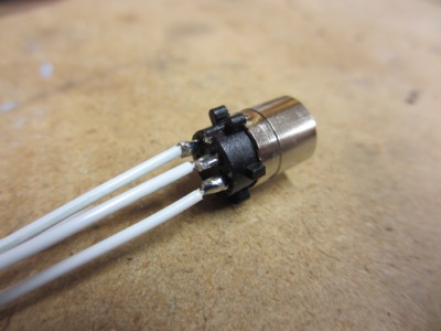
The ELT uses a fairly rinky-dink DIN connector for its power and GPS position inputs. Rather than trying to solder these tiny pins while standing on my head inside the airplane, I decided to solder them on the bench instead:
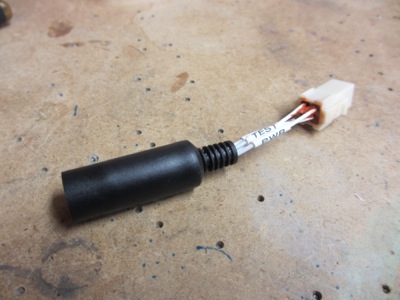
Then I fabricated a short DIN-to-Molex adapter. Inside the airplane I used a mating Molex plug with crimp pins.
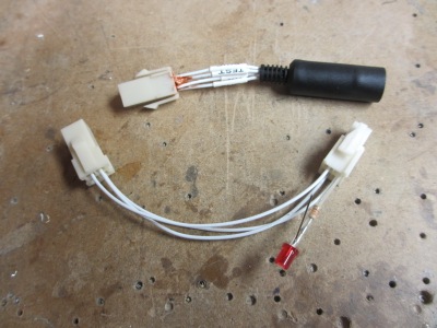
What this enabled me to do was to also build an in-situ test adapter, complete with diagnostic LED. Then instead of having to leave the wire for the LED in the airplane all the time, I can just plug this little thing into the harness and watch the LED blink when the ELT gets data. Which is what I did – sorry, it didn't photograph well, so I can't show you a picture.
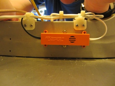
The ELT also comes with a separate little box, containing a buzzer that sounds when the ELT is activated. I suppose that would help the CAP find a crunched airplane in a forest, for example, but I expect its main purpose is to alert bystanders to an accidental ELT deployment after a hard landing or whatnot. I mounted the audio box on the aft side of the F-707 bulkhead:
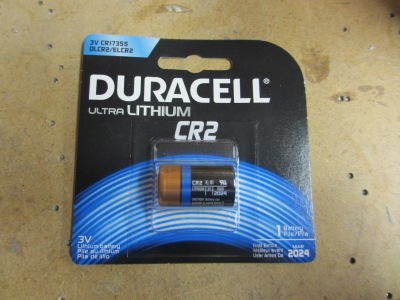
The audio box uses its own battery, an unusual 3V lithium number. I'll need to crawl back there and replace it in 2024:
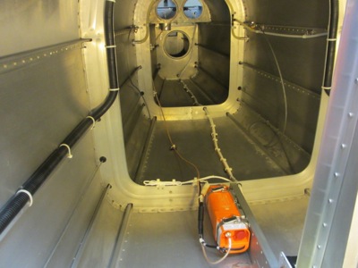
I secured all the wires that go to the ELT, and there are actually quite a few. I used plastic tie wrap anchors to route the wires to and from the audio box, whose mounting screws are visible here on the forward side of the bulkhead:
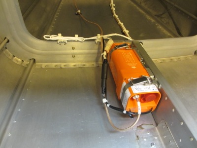
I fabbed a length of RG400 coax for the ELT antenna, and used more plastic anchors to secure it loosely to the bulkheads and floor.
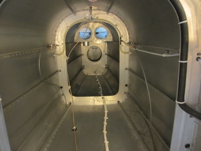
Everything is shipshape in ELT land now, I believe. Per the manufacturer's guidance, the antenna cable does not penetrate any bulkheads or aircraft structure, and is only loosely restrained elsewhere, so it can still move around and hopefully won't get cut during a… shall we say, "a deceleration that rearranges the configuration of the airframe".