Archive for June, 2015

FWF wiring complete

Sunday, June 21st, 2015

With the firewall-forward wiring finally complete, I spent the better part of a day bundling wires, attaching adel clamps, and replacing all the temporary tie-wraps with the high-temp variety. Now the FWF wiring is all safely secured, and looks pretty good too if I do say so myself. Here's a collection of photos showing the end result. I lost track of the number of adel clamps I installed today and I'm too tired to describe every one!

I also closed out the two firewall passthroughs. The wire bundle is wrapped in multiple layers of firesleeve and clamped solidly, which should keep the flames on the hot side of the firewall in the event of a bad day. I also applied copious lengths of silicone tape to seal the ends and prevent hydrocarbons from soaking into the fibers. Here's the starboard side:

And here's the one on the port side:

I will probably put some kind of sealant on the inboard side of the firewall passthroughs as further proof against fumes and carbon monoxide, but that can be done later.

Being able to check off a major family of firewall-forward tasks is huge! I'm sure I'll get stuck and frustrated again soon enough, but for now it's a great feeling to be able to call the FWF wiring done.

Ground power plug

Sunday, June 21st, 2015

The last remaining wiring task forward of the firewall is some kind of power connection for use on the ground. There are two schools of thought on how this ought to be done – at minimum, a ground power connection should be capable of charging the aircraft battery and perhaps powering the important avionics during maintenance, but some folks also like to be able to jump-start their airplane from a power cart in the event of a dead battery. The problem I found with the latter approach is that the connector required to support starter cranking current is expensive and huge, and there's not a great place to mount it without cutting into important fuselage structure. I also decided that in my electrically-dependent airplane, it wouldn't be wise to get a jump-start and then immediately go flying with a sick battery. So, my ground power circuit will be capable of connecting a battery charger or a small power supply to run the avionics, but to save weight and complexity it won't be able to crank the engine.

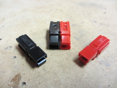
For the ground power connection I needed a connector that's lightweight and rugged but still able to handle plenty of current. I selected an Anderson Powerpole connector, which is widely used in the amateur radio field for high-current applications. These connectors are kind of cool, in that multiple poles lock together in with dovetails in a variety of orientations, allowing you to create any kind of custom connector you want. For this application, though, I stuck with the de facto standard arrangement.

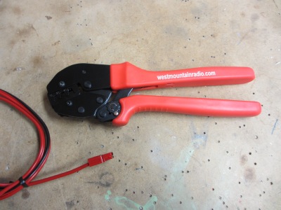
Of course, what's a new connector without a new crimper to go with it? I couldn't figure out how to buy just the dies for these connectors, at least not ones that would fit any of my existing crimper frames, so I ended up with a whole new crimper just for a couple connections. Oh well, as a tool junkie I can't complain too loudly.

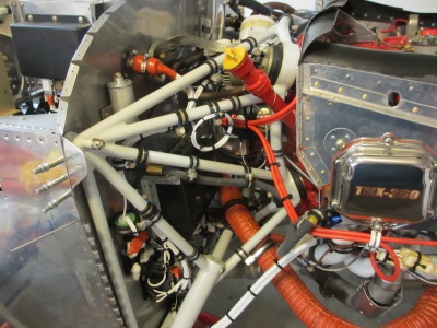
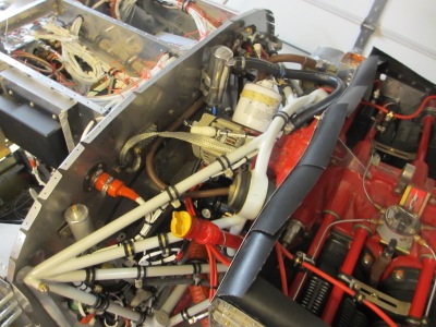
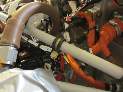
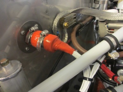
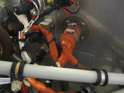
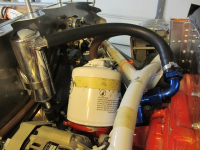
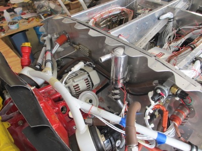
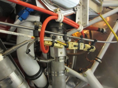
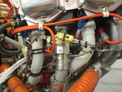
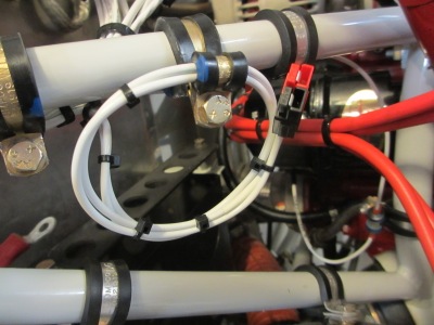
The ground power connector is secured near the oil dipstick, so that it will be possible to access it through the oil door without removing the cowl. The wiring is 12-gauge, which will be good for up to 15 amps. The black side of the connector finds its way to the main ground block, and the red side connects to the always-hot battery bus through a 15-amp fuse.

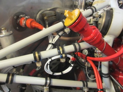
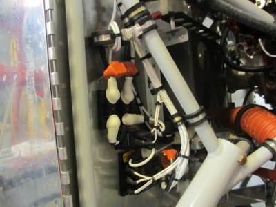
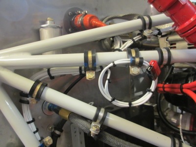
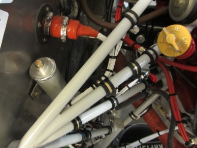
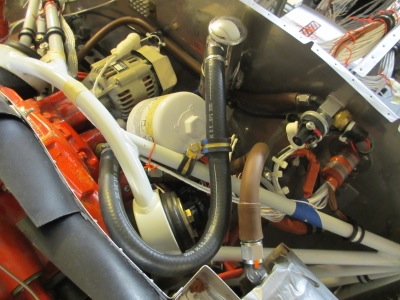
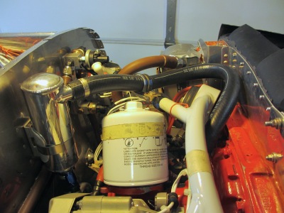
Another closeup view… The wiring is tied off and clamped in such a way that nothing can flop around and abrade itself or anything nearby. I left a decent service loop in case I decide I need to relocate the connector later on.

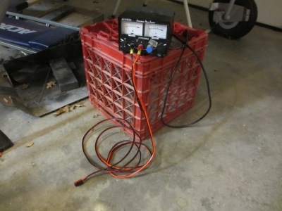
I fabricated a short Powerpole harness for my bench power supply, plus a ten-foot extension cord with Powerpole connectors on both ends. I plugged it all in and verified it works to power up the panel, so that's that. I'm sure this will get a lot of use, both during construction and afterwards.

Another breather hose

Saturday, June 13th, 2015

So, this was the previous arrangement for the engine breather hose… a 90-degree AN swivel fitting plus a 90-degree hose end:

I was driven to use this setup – which let's face it, was overcomplicated at best – by the limited options for hose routing that are available when you have an angled oil filter adapter, as my engine does. There's practically no good way to point the hose fitting that doesn't cause either the fitting or the hose to hit something else. But then I had a brain wave and thought of a much simpler solution, so I tore out the existing hose and engine fitting:

This is the new arrangement I came up with. The fitting on the engine is now a 45-degree brass hose barb, pointed towards the left side of the engine as well as somewhat forward. This allows the hose to clear the engine mount heading forward, whereupon it takes a medium-sharpish bend and turns 180 degrees back towards and air/oil separator. It does come close to the baffles and the oil cooler plumbing, but there's plenty of room for things to move around without rubbing together.

The hose is affixed to an engine mount tube with a pair of adel clamps, the purpose of which are to pull it down and keep it from rubbing on the inside of the top cowl, which is its natural tendency due to the angles involved. Although it seems at first glance like there isn't enough slack in the hose to accommodate movement of the engine, in actuality there's at least a foot of hose there, with a pretty good loop in it. This MIL-6000 hose is also fairly springy, and you can "boing" it back and forth an inch or two with your fingers. Compared to the fuel hose on the bottom of the engine, there's actually more slack in the new breather hose.

Here's another view, looking across from the right side of the engine. The engine mount and oil separator do not move relative to one another, so the short length of hose between the engine mount and firewall doesn't require any slack in it.

I have now re-engineered every piece of the breather system at least twice! I think it's truly all finished now. Here's hoping, anyway.

Thermocouple heat shields

Saturday, June 13th, 2015

Even though the thermocouple connectors are made of fairly high-temperature nylon, I didn't like how they were only a couple inches from the hottest part of the exhaust pipes. So, I bolted on a couple more radiant heat shields. Here's the left side:

And the right side: