Archive for the ‘Electrical/Panel’ Category

Fuel system check & calibration

Friday, March 15th, 2024

Today's task was to flush the fuel tanks, test as much of the fuel system as possible, and calibrate the fuel quantity gauges.

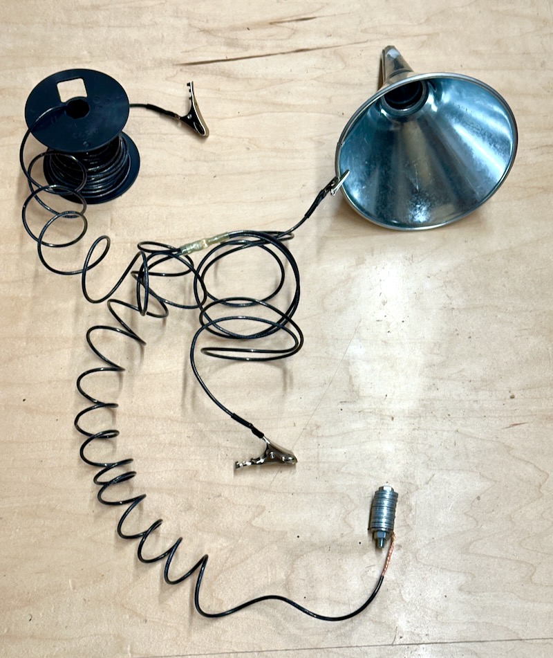
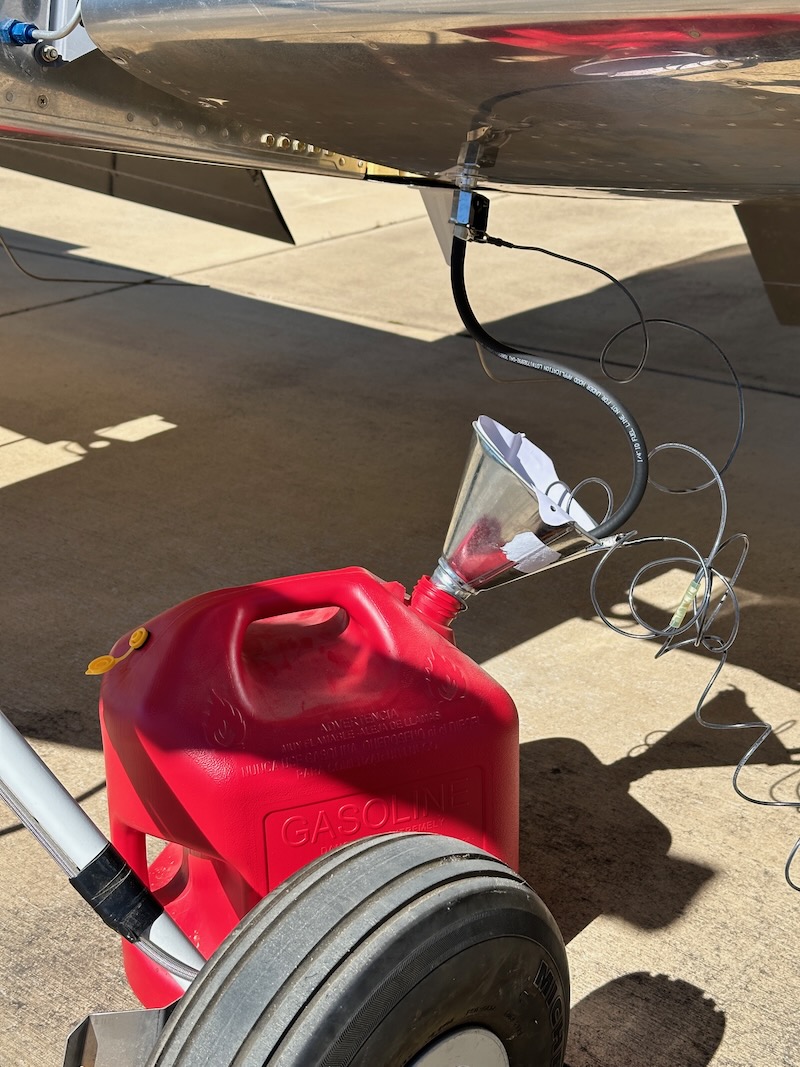
To avoid blowing myself up, I fabricated this simple grounding harness from a spool of hardware-store wire. It has one alligator clip for the airplane, one clip to attach to a metal funnel, and a third clip on the end of a long run of wire that I can connect to a ground rod if needed. There's also a length of wire with a weight on the end (made from a bolt and a stack of washers) which I can drop down the neck of a plastic gas can. The goal here is to prevent a potential difference between the airplane and the fuel container due to the static electricity generated by fuel flowing from a tank being drained, which could otherwise cause a spark. This might be overkill, but fuel flowing through rubber and plastic can do funny things, and I enjoy not being exploded.

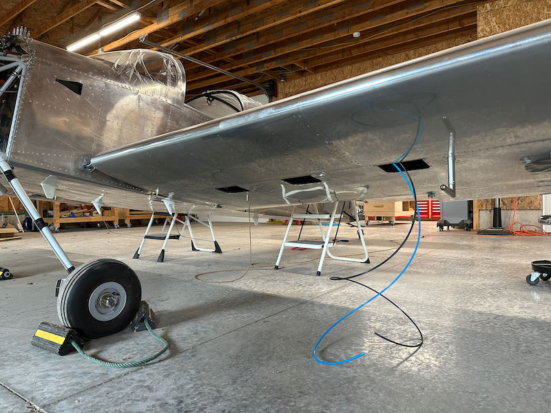
I temporarily removed the fuel tank drains, and installed a pair of ball valves with rubber fuel hose attached. With this setup and the ground rig connected, I flushed about ten gallons of avgas through each tank, draining it back into the gas cans through a clean paint filter:

Happily, I only found a few tiny particles of trash in the filters, and nothing leaked:

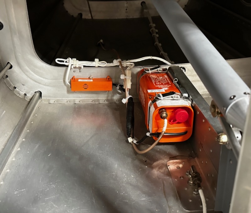
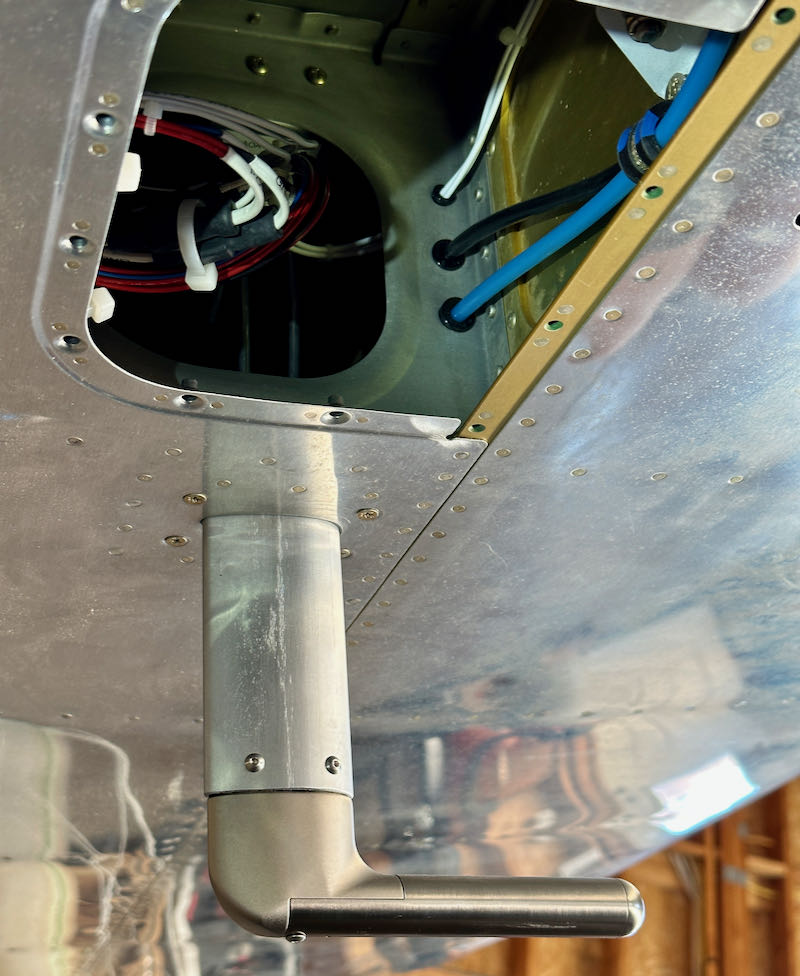
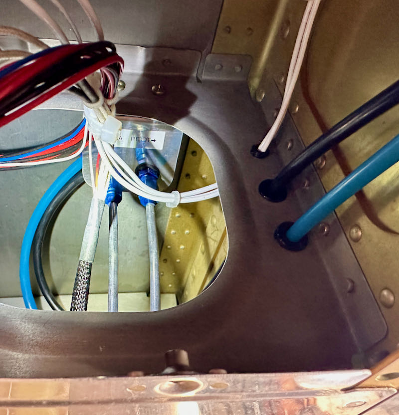
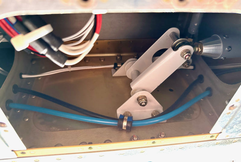
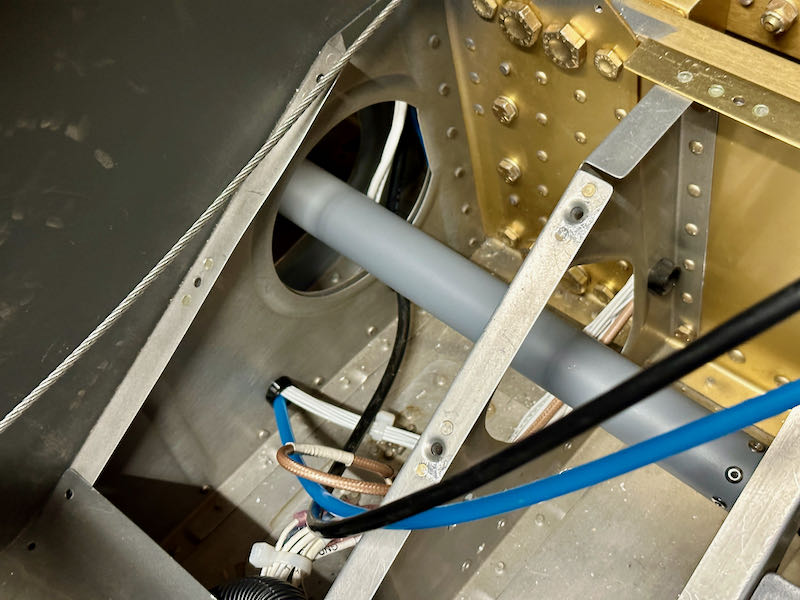
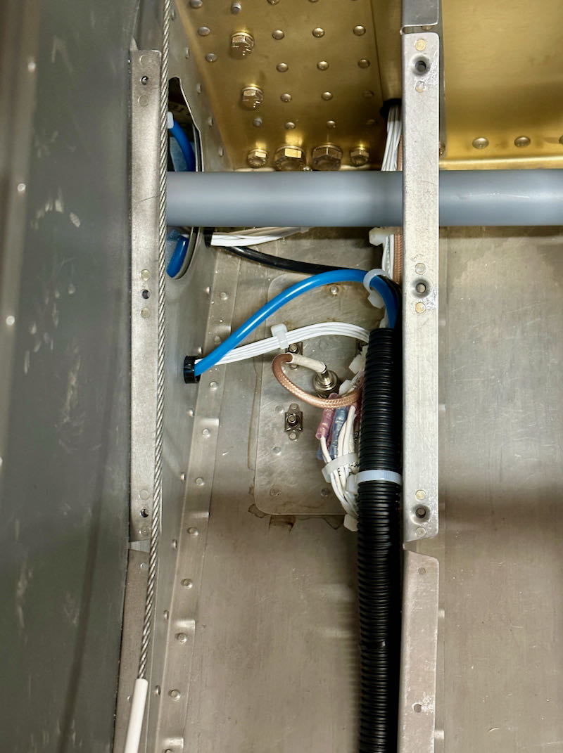
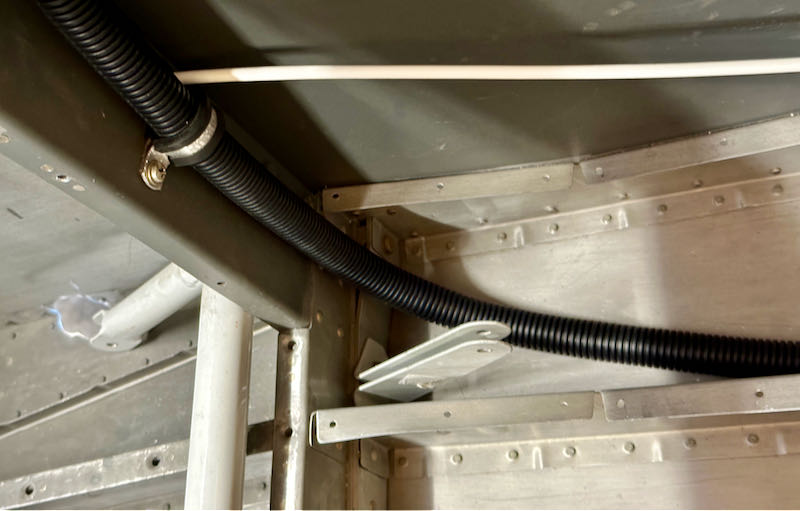
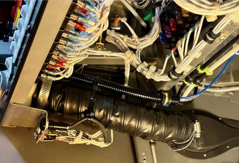
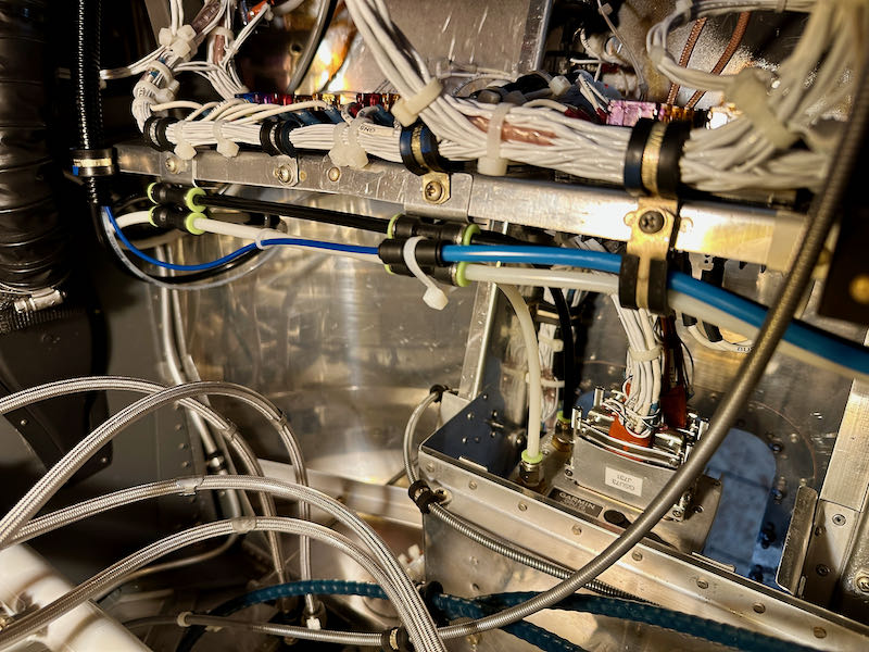
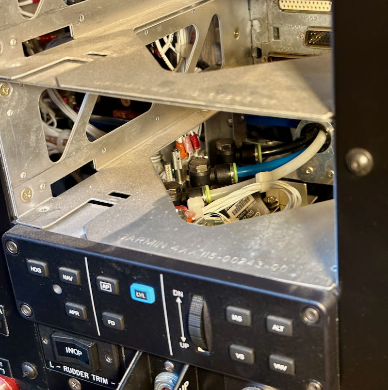
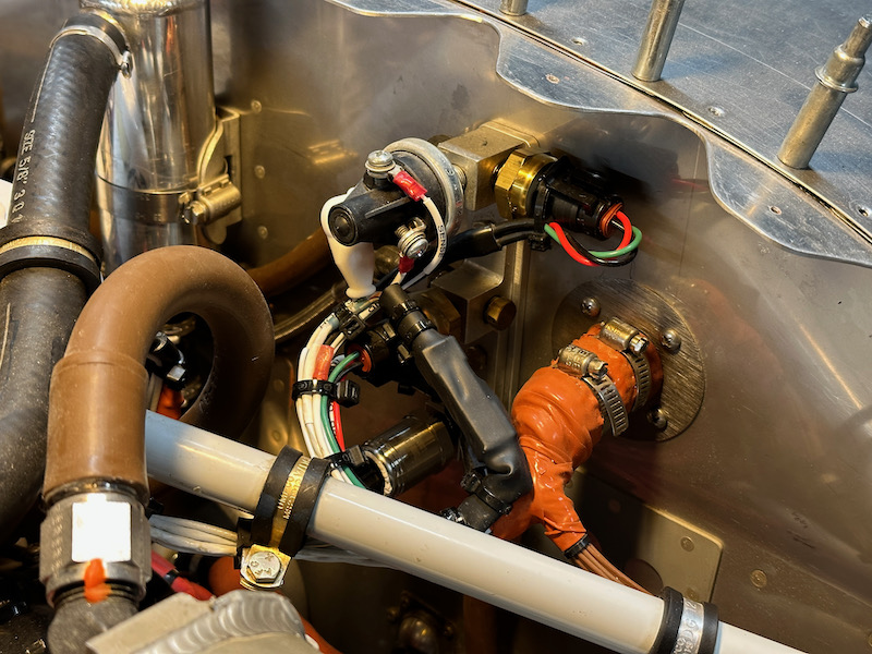
Then I disconnected the fuel hose at the inlet to the mechanical fuel pump, and used the electric boost pump to run several gallons from each tank through the fuselage plumbing and back into gas cans. This allowed me to check most of the plumbing for leaks, verify the operation of the fuel selector, and test the boost pump and fuel flow gauge. I put a lawn-mower fuel filter in the temporary drain hose to avoid putting any trash back in circulation:

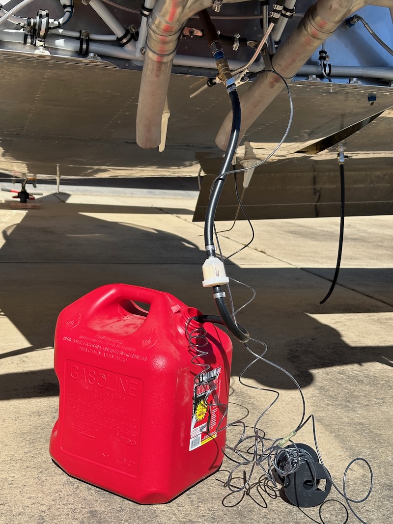
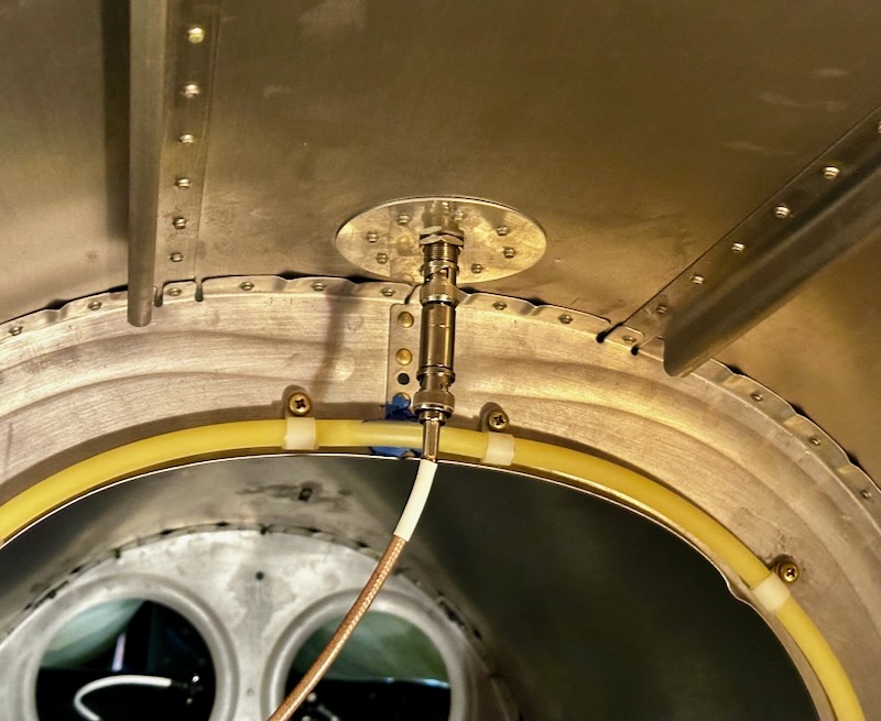
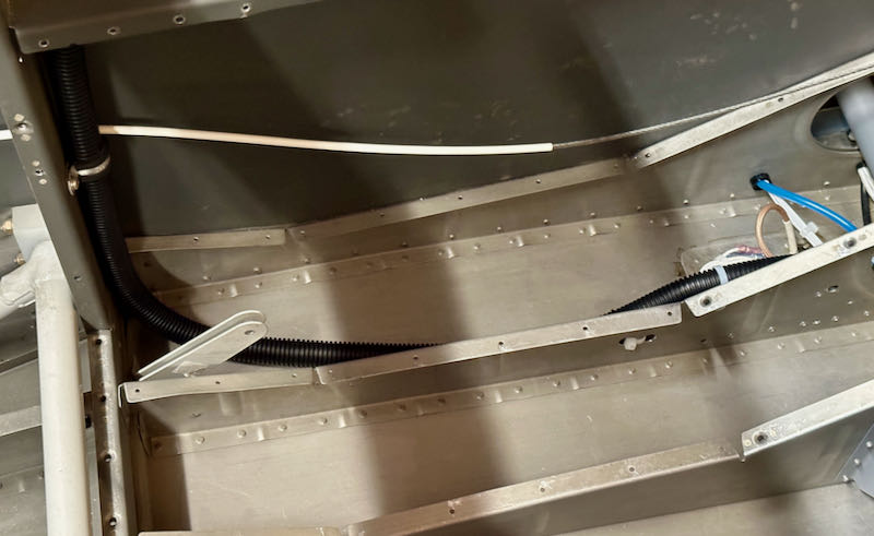
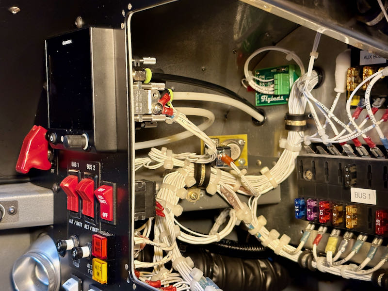
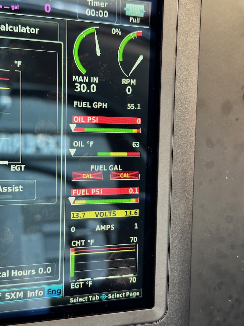
The fuel flow gauge was showing about 55 gallons per hour with the boost pump drawing from either tank. Judging by my watch, it was filling the gas can at the rate of about a gallon every minute, so that number seems believable. No fuel pressure indication here, since the hose is disconnected:

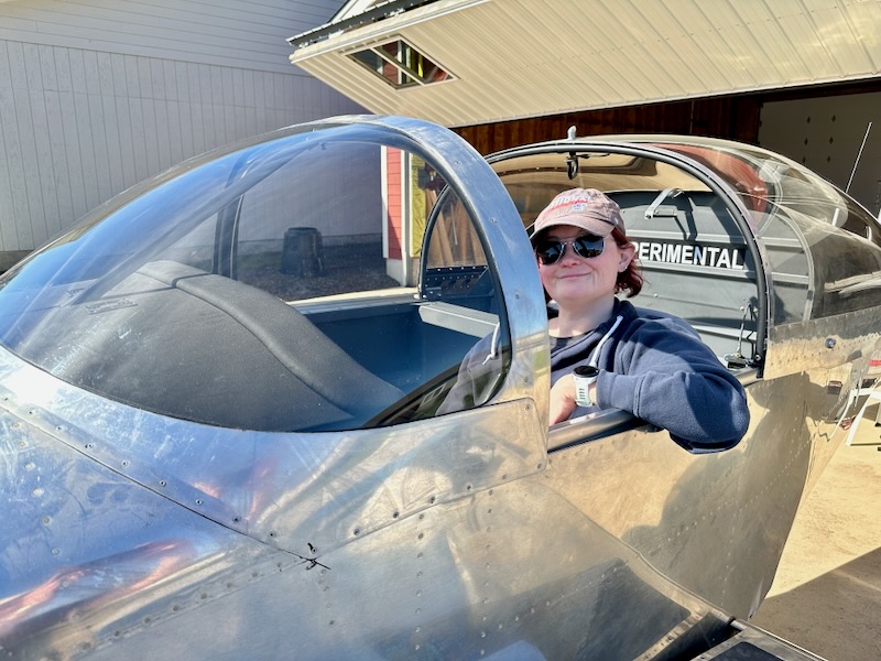
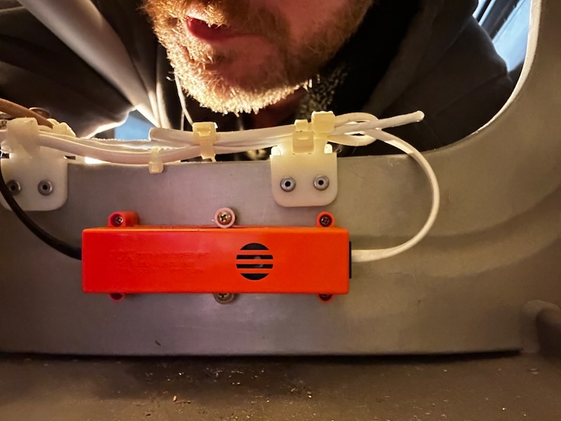
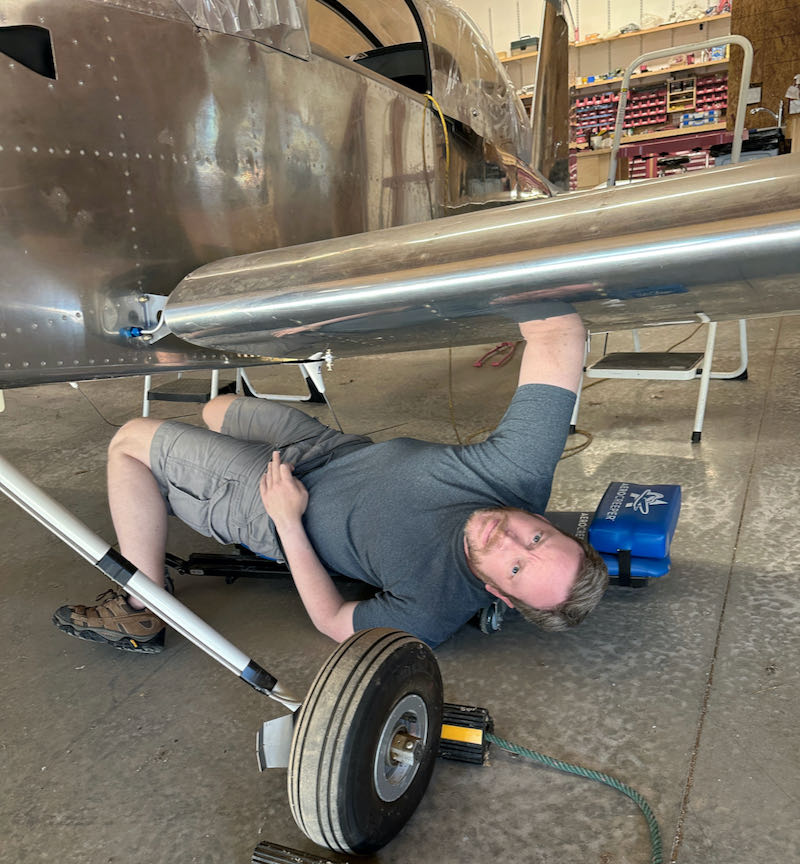
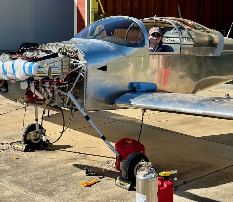
I recruited Mary to push buttons, got her situated in the seat, and then heaved the tail up onto a stand to level the fuselage:

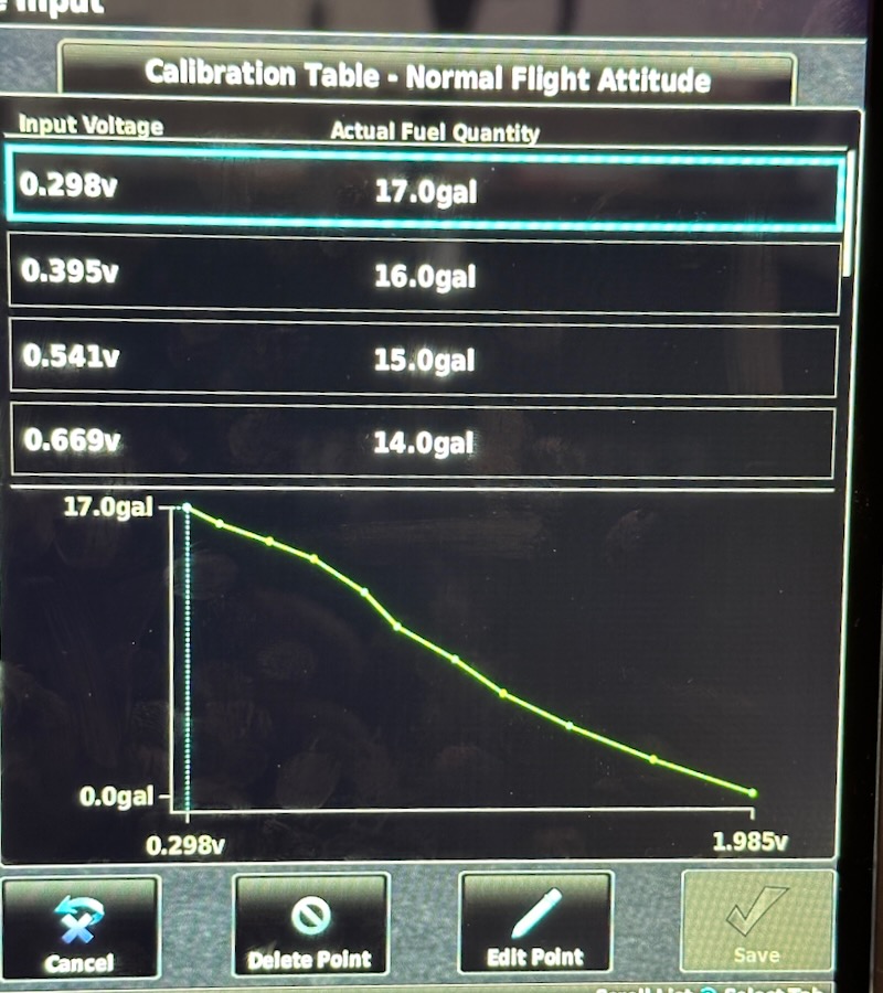
Using a calibrated fuel container, I added two gallons at a time and had Mary record each calibration point until the gauge stopped registering. For the right tank, we had no problems with the calibration process and were able to record points up to 17 gallons. Above that level, the float tops out due to the dihedral of the wing:

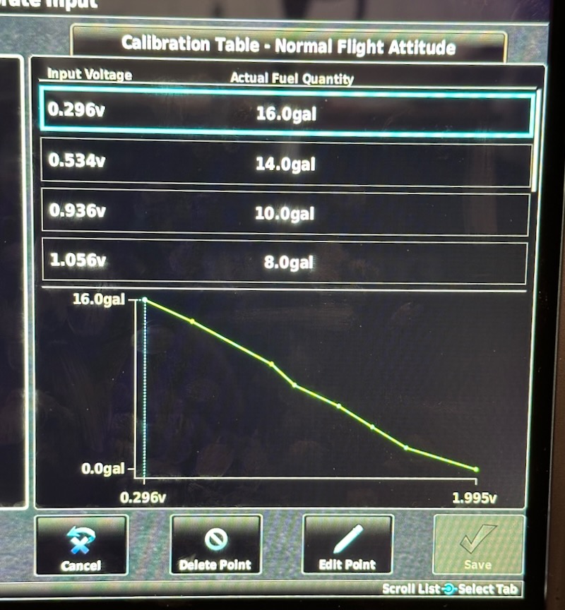
The left tank seemed to have a sticky float, requiring a lot of tapping to get it to register changes in fuel level. We were eventually able to get a believable calibration curve out of it, but I'm not completely convinced. I'll monitor this and see if it frees up with use, and hopefully I won't have to pull the sender to fix it:

After filling and calibrating each tank, we then used the boost pump to drain the fuel back into gas cans again.

Mary the long-suffering assistant rated the Classic Aero Aviator seats as "like the seats in an upscale SUV":

ELT service

Sunday, December 10th, 2023

I'm such a slow builder that the batteries in the ELT have timed out, so I need to replace them to be legal. There are three in total, starting with the one in the remote indicator in the panel:

In addition to making entries in the aircraft logs, I put stickers showing the battery expiration dates on the side of each component:

The main battery pack for the ELT itself is huge and expensive:

Despite the expense, a replacement ACK ELT battery pack doesn't come with the required o-ring, so I re-lubed and reused the old one:

The third battery is in the audio alert unit, which I quickly regretted installing on the aft side of the F-707 bulkhead where it couldn't be seen:

When I reinstalled all these units I moved the audio alert unit to the front side of the bulkhead, so it will be slightly easier to service next time:

And while I was crawling way back in the tailcone, I fitted the ELT antenna static suppressor that's now apparently required by a service bulletin:

Pneumatic plumbing

Thursday, July 20th, 2023

The pitot tube, to be useful, has to be plumbed all the way to the panel… a long journey through a lot of unhelpful structure. I used 1/4" black nylon tubing for pitot pressure and blue for AOA:

Looking up through the access panel at the plumbing:

This area is difficult to see or photograph, but the tubes loop around to connect to the previously installed fittings:

I used a longer bolt and an adel clamp to keep the tubes from fouling the aileron bellcrank:

Running the tubing all the way through the wing and into the fuselage was only barely doable! I need a skilled helper with both flexible availability and flexible arms:

The tubes take an S-turn that's impossible to photograph, then enter the fuselage through the same bushings that allow the wire bundles to pass:

I secured the tubes out of the way of the aileron pushrod, and ran them aft through a protective 3/4" plastic conduit:

The conduit runs aft under the seat floor, then up the forward face of the F-705 bulkhead:

Another adel clamp keeps the conduit out of the way of the rudder cable:

The pitot and AOA tubes, along with the white static tube, pass up through the armrest through a set of plastic bushings. Don't ask me why I chose to use three separate 1/4" bushings here rather than one single larger one. The pitot line (black) goes all the way to the panel, while the static and AOA tubes are cut short here:

I wrangled the pitot line through a piece of 3/8" conduit, along with two 1/8" tubes for static and AOA. I didn't really want to have to use this tiny tubing size, but due to the space available to run the conduit I had no choice but to use small-diameter plumbing here:

In retrospect I wish I had finished the pneumatic plumbing prior to riveting the center section cap strips. Snaking this conduit over the top of the center section and around the rollbar bolts, without being able to get my fingers on it, was very tough:

The reducer fittings that convert the static and AOA tubing from 1/4" to 1/8" will be hidden behind the interior panels, aft of the pilot's elbow:

Forward of the panel, the plumbing conduit terminates at an adel clamp screwed to the bottom of the subpanel, and the various tubes branch out from there:

This photo is looking up at the bottom of the subpanel, with the nose of the airplane towards the bottom of the picture. I had previously done most of the under-panel plumbing prior to riveting on the forward top skin, but in my haste neglected to document it. Tee fittings are screwed to the subpanel flange with little brackets I made from scrap, and an adel clamp or two keeps everything constrained. To this I zip-tied the AOA tube, adapter-ed back up to 1/4" interface with the #2 ADAHRS:

One branch of the plumbing brings pitot and static to the G5 backup instrument, as well as connecting to the alternate static port:

The #2 ADAHRS lives underneath the radio stack, and is difficult to photograph, but it now has all three of its pneumatic ports plumbed:

I have no good way to leak-check any of this plumbing, but I did apply lung pressure to the pitot tube and suction to the static ports, and confirmed the expected results on the cockpit displays. So that's good enough for me to call the instrumentation air plumbing complete.

Pressure sensors replaced

Monday, March 6th, 2023

A service bulletin on Kavlico fuel and oil pressure sensors was published a couple years back, advising of a potential for them to leak. I decided to replace them both just to be safe. I was able to remove them both while leaving the transducer manifold in place, although it was a tight fit due to how crowded this area is:

I replaced the oil pressure sensor with another Kavlico sensor – the gold thing at the top – this time the supposedly non-leaking kind. I found that the correct Kavlico fuel pressure sensors were difficult to come by, so I was forced to buy one of Garmin's new private-label sensors – it's the silver cylinder at the bottom of the manifold. The manifold pressure sensor I left alone, since it wasn't subject to the same service bulletin.

At least the wiring connections are the same as the old sensors, so not a bad job overall.

Wing wiring & landing lights

Wednesday, August 10th, 2022

I know, I haven't updated this for too long… been busy with other things, as usual.

After attaching the wings to the fuselage, I spliced the wing wires into the fuselage wires – a job that was electrically simple but mechanically tedious due to having to work in the confines of the under-floor area.

It's difficult to see here, but I slit pieces of rubber fuel hose and slipped them over the inboard edges of each spar web. This is to protect the wire bundles that run through the pre-located holes, which were uncomfortably close:

Given that technology is moving faster than I am finishing this airplane, LED lights have become commonplace, so instead of reinstalling my old HID landing lights I opted for a pair of Flyleds combo landing/taxi lights. These are next because they combine the functions of both landing and taxi lights, with the latter canted downward for proper alignment in taildragger applications like mine.

I was a bit surprised that this lighting kit requires you to cut and grind on the assembled PCBs to make them fit, but I managed it without destroying anything:

I had to modify the opening in the Duckworks mounting brackets to allow the taxi lights to fit:

I added a wiring grommet in the mounting bracket, with a matching notch in the main PCB. Frankly I don't love this solution, but given that the wiring connections attach to the front side of the lights, this is the best I could come up with.

I added 4-pin Molex connectors, with the landing light pins being inserted after installation. This will make future removal a challenge, but that's a problem for future me.

Looking through the wingtip rib lightening hole, this is what the light unit looks like installed. It doesn't fit through the rib but does just barely fit through the lens cutout in the wing leading edge. You can see how the taxi light is angled downward, which results in it being more or less level in the taxi attitude.

View of the installed light prior to attaching the lens:

Final result: