Archive for the ‘Elevators’ Category

Empennage fairings part III

Monday, February 19th, 2007

Okay, so the first try at closing up the elevator tip fairing didn't turn out so well. I forgot to take a picture, but basically the fiberglass had nothing to adhere to (the lead was coated with tape to prevent sticking) so it was very wavy and uneven. Also, since I only used three plies of 1 oz cloth it was very flimsy.

One of the nice things about fiberglass is that if you screw up you can usually grind off your mistake and try again. This time I'm going to try using a piece of aluminum to provide the structural strength, and the fiberglass will just be there to hold it all together. I made a forward bulkhead out of some scrap alclad (0.040" I think), scuffed it up so the epoxy would stick, and temporarily attached it to the counterweight with double-sided tape.

Then I laid up three layers of 5 oz cloth, with a single layer of 1 oz cloth over the top to help fill in the weave. We'll see how this turns out.

I must say, the new style of elevator counterweight is a real pain. The old arrangement seems like it would allow you to spend a lot less time messing around with fiberglass to get the tip fairing to come out just right. But what do I know…

Back to the rudder, I mixed up another batch of micro and applied it here and there. This photo is kind of hard to interpret, but what you're looking at is a glob of micro applied to the front face of the rudder cap, with a piece of scrap alclad (covered with duct tape to make it non-stick) taped in place to make it cure with a nice smooth, even surface.

My cat wanted to help write this entry:

More empennage fairings

Sunday, February 18th, 2007

Today was an all-fiberglass day. Sorry, no action shots – hard to hold a camera with sticky fingers.

I sanded most of last night's primer off of the top rudder fairing, then put another glob of filler on the front where it still needs to be built up. My favorite tool for this kind of sanding is a 3" red scotchbrite disc in a die grinder turned down to low pressure. I also use a 60 grit sanding block where necessary, but power tools make the job go faster.

While the rudder fairing was curing, I got out one of the elevator tip fairings and started playing with it. The lead counterweight at the front is going to throw some sand in the gears of my plan to make removable empennage tips. It is tempting to permanently attach the elevator tips and just glass over the counterweights, but I'm still going to try to make them removable because I love a challenge. (Mary would probably say that I'm just plain stubborn)

I laid up three layers of lightweight cloth, sufficient to cover over the open end of the fairing where the counterweight lives. It's not much to look at right now because the peel ply is blocking the view. Underneath is a layer of electrical tape to prevent the fiberglass from sticking to the lead. With any luck this will form the starting point for a closed-end fairing that will cover the counterweight but will still be removable – we'll see tomorrow.

Hours later, the second coat of filler on the rudder was dry, so I proceeded to sand away at it. The shape is almost there now – just needs one or two more layers.

After shooting a coat of primer to help me check the finish, I put more filler on a few spots to fix some of the more egregious pinholes. My goal is just to get the basic contour correct – I'll leave the detailed surface finish work to the painter.

In the middle of all this, I bought and put together this particle board file cabinet for Mary. I found myself thinking how awesome it would be if airplanes were put together with quarter-turn fasteners. I'd already be flying!

Worked on pitch controls

Monday, September 4th, 2006

Not much got done on the airplane today because I was tired. However, I did figure out what was wrong with the F-789 forward elevator pushrod… it's not that it was too short to allow sufficient down elevator travel, it's that the control column was hitting on the seat ribs. I dremeled out some small bites from the F-716 seat ribs, just enough to allow full forward stick plus about 1/16" extra for clearance.

Another photo of the other side. The duct tape is to protect the finish on the control column.

I likewise had to trim the removable parts of the two center seat ribs:

Once I had full stick travel, I put in the pilot's stick and seat in order to adjust the neutral stick position. Man, these seats are comfortable as heck.

Here's me doing ergonomics testing. I was in and out of the fuselage a half dozen times before I got it the neutral point adjusted where it fell easily to hand. The pushrod has a little more than the minimum required thread engagement, which is good. If you're reading this and you haven't fabricated your F-789 yet, do yourself a favor and make it about 1/4" longer than what the plans call for.

Yes, I made airplane noises:

Working on empennage attach

Sunday, July 23rd, 2006

More work on the empennage attach chores today. I hauled the elevators down from the airplane storeroom, and spent a bit of time filing metal away from the left elevator where I noticed it was a little close to the outboard edge of the trim tab. Good clearance all around now.

Then I temporarily mounted them to the stabilizer. Hey cool, the tail has moving parts now!

The next step in the plans is to make the elevator pushrods. I cut them to length using my handy dandy miniature chop saw:

I had previously picked up a quart of this SEM self-etching primer, which is pretty similar to the GBP 988 I've been using elsewhere, just in liquid form instead of a spray can.

To prime the insides of the pushrods, I taped over one end, poured liquid primer down the other end and taped it up, and then sloshed it all around inside. Since these pushrods are so long, especially the aft one, using the liquid primer here was easier than spraying a ton of primer down the inside like I did with the previous ones.

After the insides were all coated with primer, I uncorked the ends to let everything dry out.

While the pushrods were drying, I got out the vertical stabilizer attach plate and clamped it in place to test the fit.

One of the first things the plans have you do when you begin the process of attaching the vertical stabilizer is to cut 5/8" off the VS front spar. Uh, gee guys, it sure would have been nice to have known about this when I was building the thing in the first place. It would have been a lot easier to trim the spar before it was, you know, all riveted in place and stuff. Further evidence that the RV-7 is a Frankenplane: Wings and vertical fin from an RV-8, fuselage and rudder from an RV-9, and instructions from who the heck knows where. Oh well, they fly nice and look real purty.

I got as far as clamping the vertical stabilizer in place before I had to knock off for the night. I'll be away at Oshkosh for the rest of the week, but it's nice to know that I have this thing-that-looks-a-lot-more-like-an-airplane-now waiting in the garage for when I get back…

Mounted the horizontal stabilizer

Saturday, July 22nd, 2006

I was going to work on the brake lines some more today, but I didn't receive all the parts I ordered earlier this week – one box of AN fittings from Wicks got shipped to the wrong address and subsequently lost. Kudos to the Wicks people, though – they were able to help me figure out what happened and get a replacement order on its way, at no charge – on a Saturday. Everybody go give Wicks some business, they deserve it. Even if you don't need any airplane parts, they're having a sale on toy gliders, and who doesn't like toy gliders? Nobody, that's who. If there are any such people I refuse to accept it.

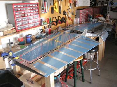
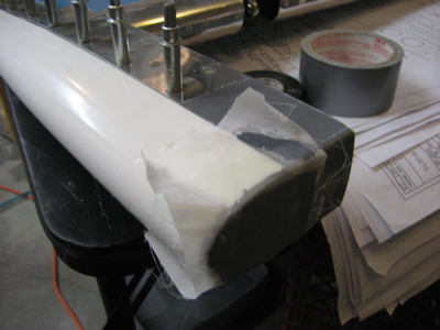
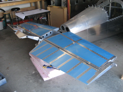
Anyway, so not enough parts to work on the brakes. The only things left in the fuselage plans are mounting the wings, which I already decided not to do yet, and mounting the tail. Okay, let's mount the horizontal stabilizer today. I dug out the HS and elevators from the storeroom and rigged them on the bench to make sure everything still fits:

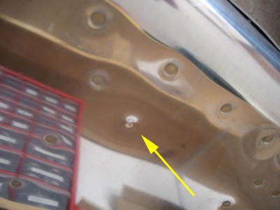
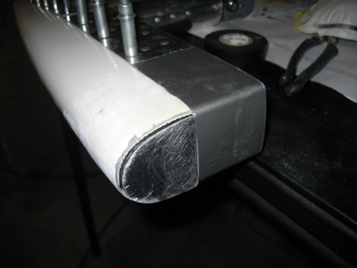
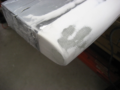
Somehow, the bottom of my left elevator has developed this mysterious dent. I'm not sure what caused it. At least it's on the bottom surface – it will probably eventually be joined by more little dents as rocks and stuff hit the bottom of the tail when the tailwheel is on the ground.

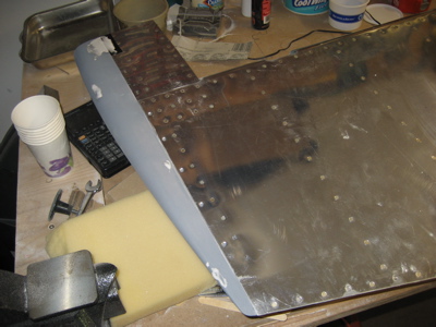
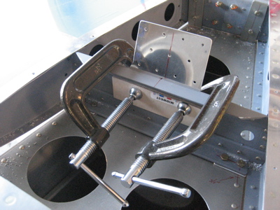
I clamped both elevators exactly in trail, to align everything for the drilling of the elevator control horns.

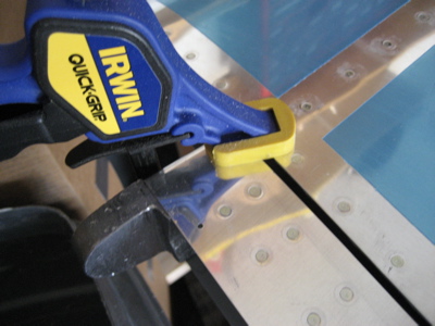
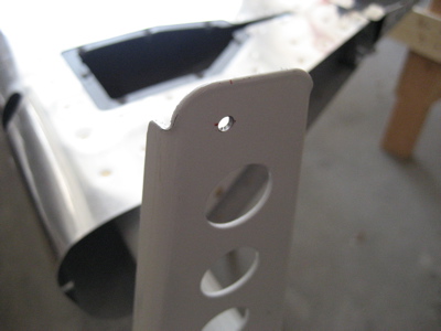
Some people have trouble with their elevator horns not lining up very well. They're welded individually, so it's likely that there will be some misalignment when you bring the two elevators together. Mine were almost exactly identical, though, which is good.

The left horn was just a fraction of an inch forward of the right one, so the left elevator was the one to get the first hole drilled in it. I took the elevator back off the stabilizer to make sure the pilot hole for the pushrod bolt was in the right spot.

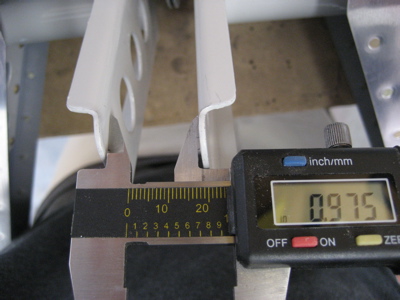
With everything back together again, I measured the distance between the two faces of the control horns at the approximate location of the bolt hole…

Then I made a simple drill jig out of a sandwich of 3/16" birch plywood squares glued together, with a hole drilled perpindicular to the face with a drill press. This got clamped between the elevator horns, and then I transferred the pilot hole across to the right elevator horn. You have to do it this way because you don't want the bolt that joins the two elevator horns to the pushrod to be crooked.

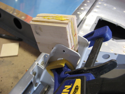
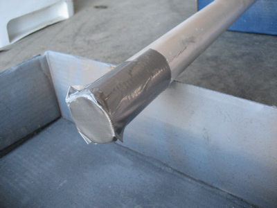
I drilled and then reamed the pilot holes up to 3/16", then trial fitted a bolt. Yep, I'd say that's straight all right.

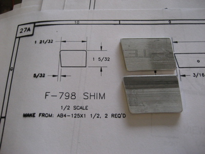
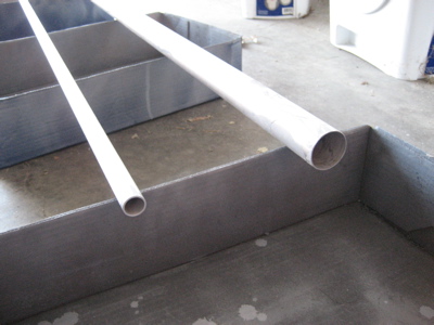
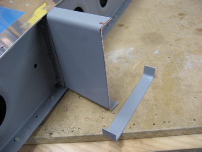
Next I made the F-798 shims, which go between the HS mounting flange and the aft fuselage deck. This photo makes them look like they're not the right shape, but they are – must be the camera angle.

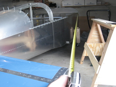
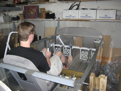
I had to rearrange the garage to let me fit the horizontal stabilizer onto the fuselage – then, I clamped it to the aft fuselage and measured, measured, measured until I got everything lined up and straight. To help make sure the stabilizer was exactly perpindicular to the long axis of the fuselage, I drilled a hole in a tape measure; by clecoing it to one particular rivet hole on either side of the firewall and pulling it tight, I was able to measure the distance from the firewall to the stabilizer tips without anyone around to hold the other end for me (important tip for those of us building mostly solo!).

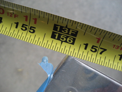
I tweaked and tweaked until both sides measured exactly the same – 156 3/16" in this case. The hole in the tape measure was right at the 1" mark, by the way.

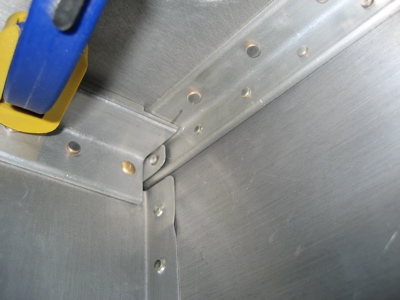
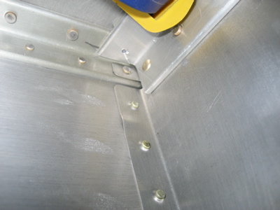
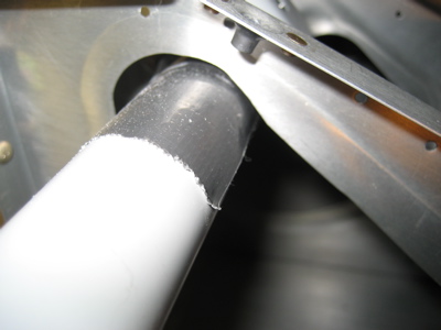
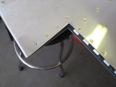
There are four bolts that hold the forward HS spar to the fuselage. The two outboard ones are a real pain – each of those bolts has to go through five or six layers of stuff, which means you have to do a ton of very careful measuring to make sure that that one hole has adequate edge distance on every part it goes through. Here's a view of the underside of one of these areas, where the bolt has to go through the longeron, a spacer, and an angle (and then the aft deck, the F-798 spacer, and the forward HS mounting flange). Of course, the quickbuilders also seem to have cut the F-710B angle a little bit short on my airplane, reducing the margin for error even further. By the way, you can't actually see any of this stuff inside the fuselage – I had to use an inspection mirror and take lots of photos like this in order to get an idea of how things were going to work out. Thank goodness I have a small camera…

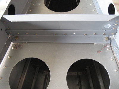
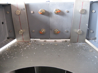
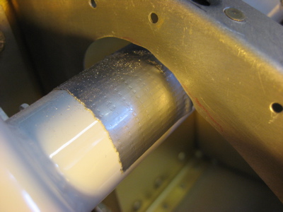
After lots and lots of measuring, I got out the drill and made some pilot holes for the outer forward holes. Hooray, they both came through right where I wanted them. Here's a view of the right side – the left is similar:

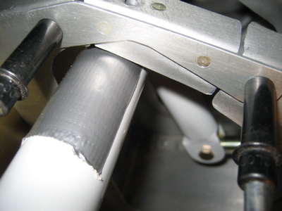
I drilled and reamed the holes up to 3/16", then put some nuts and bolts in. You can see the shims in place there – I decided to ignore the part where the plans tell you to drill the stabilizer to the fuselage without the shims in place, and then put the shims in and match drill the holes. It seemed like it would be easier just to clamp the heck out of everything and drill all the parts all at once, which is what I did. Everything looks good here.

Much measuring later, the other pair of bolts are in. To properly locate these, I had to take the stabilizer off and measure, but I'll spare you the boring details.

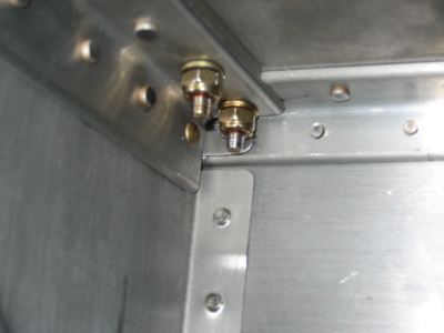
Here's a view of the nuts on the left side:

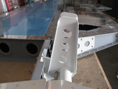
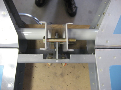
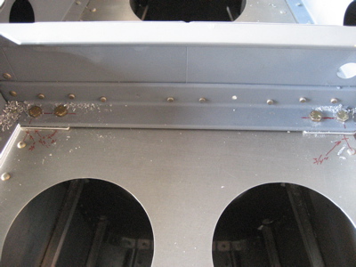
After lots more measuring, here are the other four bolts that hold on the rear stabilizer spar. I used a 3/16" drill bit as a spacer between the rear spar and the aft deck, as suggested by the plans. This puts the stabilizer at a 0° angle of incidence with the aft deck and longerons, which I verified through careful measuring. None of the hole locations on this end of the stabilizer are marked for you either, but at least you can see what you're doing a little better.

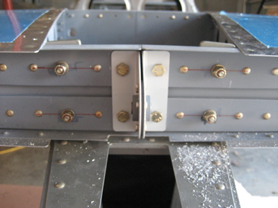
Careful measuring pays off – the bolts are centered vertically on the stabilizer reinforcement bars, and almost exactly on the centerlines of the stabilizer mounting bars. Acres of edge distance everywhere.

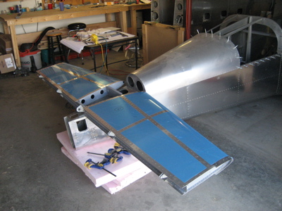
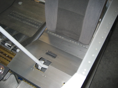
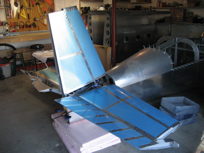
It's kind of starting to look like an airplane!

Not shown in the above photos are the hours I spent getting things lined up, taking the stabilizer off to mark something, measuring another dozen times to line things up again, etc. You only get one chance at this so I wanted to make sure that everything was as precise as I could make it. Fortunately, It all seems to have turned out pretty well.