Archive for the ‘Rudder’ Category

Empennage fairings part III

Monday, February 19th, 2007

Okay, so the first try at closing up the elevator tip fairing didn't turn out so well. I forgot to take a picture, but basically the fiberglass had nothing to adhere to (the lead was coated with tape to prevent sticking) so it was very wavy and uneven. Also, since I only used three plies of 1 oz cloth it was very flimsy.

One of the nice things about fiberglass is that if you screw up you can usually grind off your mistake and try again. This time I'm going to try using a piece of aluminum to provide the structural strength, and the fiberglass will just be there to hold it all together. I made a forward bulkhead out of some scrap alclad (0.040" I think), scuffed it up so the epoxy would stick, and temporarily attached it to the counterweight with double-sided tape.

Then I laid up three layers of 5 oz cloth, with a single layer of 1 oz cloth over the top to help fill in the weave. We'll see how this turns out.

I must say, the new style of elevator counterweight is a real pain. The old arrangement seems like it would allow you to spend a lot less time messing around with fiberglass to get the tip fairing to come out just right. But what do I know…

Back to the rudder, I mixed up another batch of micro and applied it here and there. This photo is kind of hard to interpret, but what you're looking at is a glob of micro applied to the front face of the rudder cap, with a piece of scrap alclad (covered with duct tape to make it non-stick) taped in place to make it cure with a nice smooth, even surface.

My cat wanted to help write this entry:

More empennage fairings

Sunday, February 18th, 2007

Today was an all-fiberglass day. Sorry, no action shots – hard to hold a camera with sticky fingers.

I sanded most of last night's primer off of the top rudder fairing, then put another glob of filler on the front where it still needs to be built up. My favorite tool for this kind of sanding is a 3" red scotchbrite disc in a die grinder turned down to low pressure. I also use a 60 grit sanding block where necessary, but power tools make the job go faster.

While the rudder fairing was curing, I got out one of the elevator tip fairings and started playing with it. The lead counterweight at the front is going to throw some sand in the gears of my plan to make removable empennage tips. It is tempting to permanently attach the elevator tips and just glass over the counterweights, but I'm still going to try to make them removable because I love a challenge. (Mary would probably say that I'm just plain stubborn)

I laid up three layers of lightweight cloth, sufficient to cover over the open end of the fairing where the counterweight lives. It's not much to look at right now because the peel ply is blocking the view. Underneath is a layer of electrical tape to prevent the fiberglass from sticking to the lead. With any luck this will form the starting point for a closed-end fairing that will cover the counterweight but will still be removable – we'll see tomorrow.

Hours later, the second coat of filler on the rudder was dry, so I proceeded to sand away at it. The shape is almost there now – just needs one or two more layers.

After shooting a coat of primer to help me check the finish, I put more filler on a few spots to fix some of the more egregious pinholes. My goal is just to get the basic contour correct – I'll leave the detailed surface finish work to the painter.

In the middle of all this, I bought and put together this particle board file cabinet for Mary. I found myself thinking how awesome it would be if airplanes were put together with quarter-turn fasteners. I'd already be flying!

Working on top rudder fairing

Saturday, February 17th, 2007

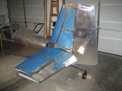
I decided that I should work on the empennage tips next, because it will be a lot easier to mess with them while I have the tail removed from the fuselage. Once the engine goes on I'll have to keep the tail attached to prevent the fuselage from tipping over on its face, so I'm trying to get as much done on the empennage while I have the opportunity.

For no particular reason I decided to start with the top rudder fairing. I trimmed the flanges enough to get the part to fit onto the rudder, and match drilled #30 holes through the skin into the fiberglass.

It isn't a terrible fit, although it is quite a bit shorter than it needs to be. I'll have to build up the forward face with filler.

The plans have you attach the fairing to the rudder skin with flush pop rivets. A lot of people use filler to make their fairings match the contour of the empennage surface, then use a layer of fiberglass to hide the joint between the aluminum skin and the composite fairing. Me, I really like the look of a well-fitted fairing with a perfect, visible seam between the two parts, so I decided to steal Randy Pflanzer's method. He made his fairings removable by using 4-40 screws and nutplates instead of blind rivets, which lets you take the fairing off to clean up the join line.

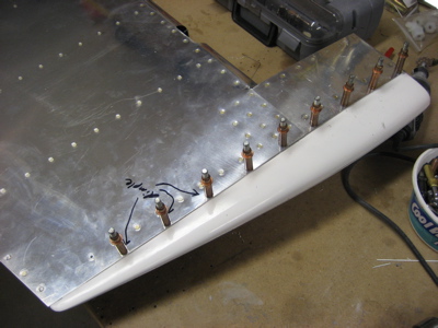
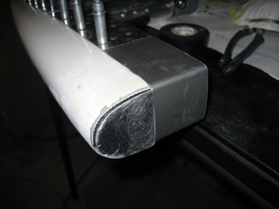
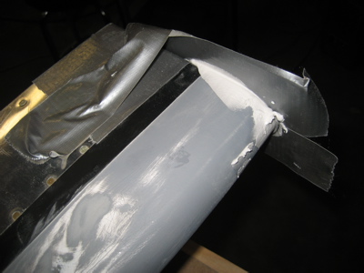
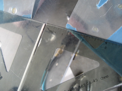
I riveted nutplates to the fairing, using a thin strip of alclad as a backing strip to keep the rivets from pulling through the fiberglass. On the first side I did (facing down in this photo) I used the same rivets to attach the nutplates to both the aluminum and the fiberglass. That turned out to be a pain to do properly, so on the other side I first riveted the nutplates to the aluminum strip, then riveted the strip to the fairing with one rivet between each pair of screw holes. That way turned out a lot better, since I could do the tricky riveting of those tiny little nutplates out in the open where I had better access.

By the way, the gaps in the alclad strips in the photo above are there because I made the them out of scrap and I didn't have anything long enough to span the full length of the fairing.

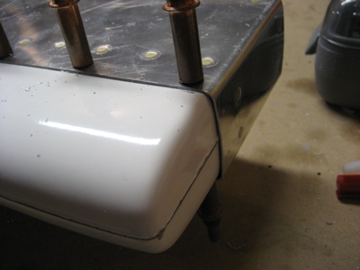
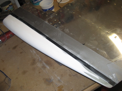
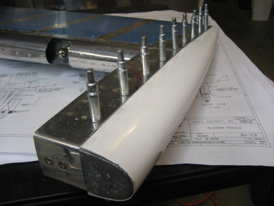
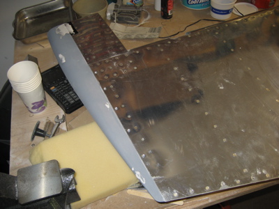
Here's an initial view of how the fairing looks when screwed in place. A #4 flush screw fits in the same dimple as a 1/8" rivet, and I really like the look of the visible fasteners. There is about a 1/16" gap along the join line, which will need filling.

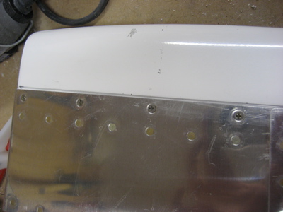
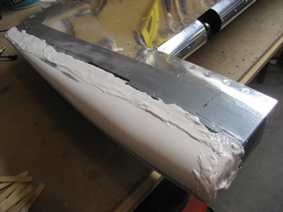
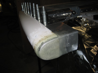
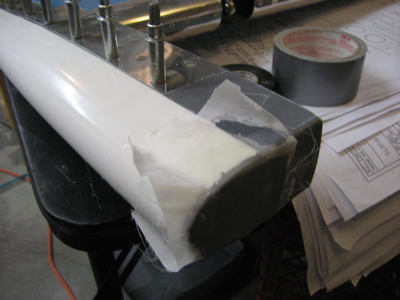
I protected the rudder skin with a layer of electrical tape (very thin but rugged enough to resist sanding) and some duct tape too for good measure. Then I used some 60 grit to knock down the high spots in the fairing. The very tail end was the worst spot, as the fairing was quite a bit thicker than the rest of the rudder back there.

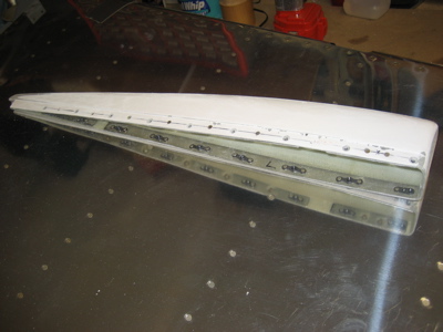
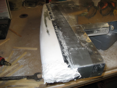
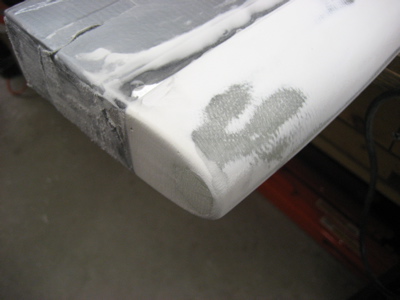
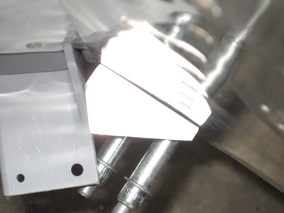
Then I mixed up a batch of epoxy and microballoons that was about the consistency of peanut butter, and slathered it all along the join line, making a special effort to try and force it down into the gap. I also tried to build up a big glob of filler on the forward face where the fairing is too short, but I expect I'll have to revisit it a couple more times in order to get enough material where it needs to be.

I'll let the whole mess dry overnight, then sand off all the excess and see where it leaves me.

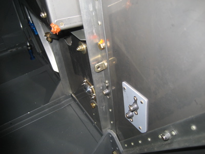
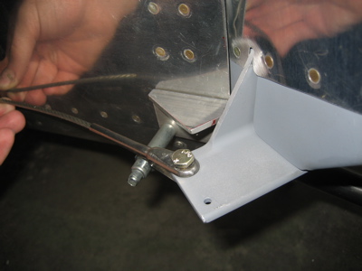
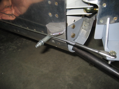
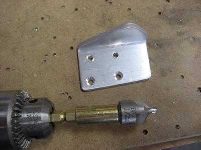
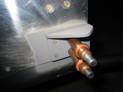
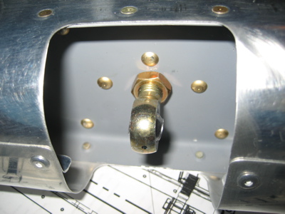
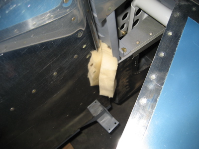
Oh yeah, while I was doing stuff in the airplane workshop I installed the eye bolts through the firewall, to which the rudder pedal return springs will attach.

Made rudder stops

Sunday, September 3rd, 2006

If I worked at a real airplane factory, I'd get fired for taking like eight hours of work over two days to make these stupid little rudder stops. Of course it doesn't help that the design requires each set of stops to be tailor-made to the individual aircraft. I spent a huge amount of time measuring, making and discarding test pieces, and fiddling around with templates. Out of absentmindedness or frustration I forgot to take any photos of this process, so here's a shot of the first rudder stop I was able to produce that actually fit:

You can see that I've temporarily installed the rudder cables to make sure that the rudder stops and cables don't get tangled up at any point along the full swing of the rudder.

Here's an overexposed overhead view showing the angle the rudder horn is at when it hits the stop. Lots of cutting and filing to get to this point.

It means nothing unless it has that swing – when the rudder hits the stop and the elevators are neutral, it's just a shade over an inch from the rudder to the inboard corner of the elevator trailing edge. Plenty of clearance to keep the tail surfaces from banging together, and slightly more travel than is called for in the plans. Extra rudder travel is good, it means extra rudder authority. I've heard of some people making this dimension more like 1/2", but that seems like cutting it bit fine to me.

After I was finally satisfied with the fit, I rounded off all the corners and made the stops look pretty, and countersunk the rivet holes. These two I was able to do with the countersink cage; for the two that are closer to the flange, I used this setup to make the countersinks freehand.

I primed the stops and the skin underneath, then riveted them halfway on. The plans call for CS4-4 blind rivets in the front two holes. I used CherryMax CR3212-4-4's instead since I have a whole drawerful; the literature says they are something like 3x stronger in shear. The aft two holes will have to wait for now, since I can't squeeze those rivets until I remove the vertical stabilizer.

This photo is to remind me that I haven't torqued any of the control surface jam nuts yet – my torque wrench has a 1/4" drive and my crow's foot wrenches take a 3/8". Time to go to Sears!

Hung the rudder

Sunday, August 27th, 2006

I didn't work much on the plane today, but I did get the rudder hung on the vertical stabilizer. It swings without any binding at all, which I suppose means that everything is straight. I'm not completely sure that I have the two hinge lines parallel, so I will probably remove and tweak it a few times before I torque the jam nuts.

Holy cow, the tail is getting huge!

Since the rudder stops aren't in place yet, I jammed a couple pieces of foam rubber beteween the rudder and the vertical stabilizer spar, to keep the rudder from swinging too far and getting banged up.