Archive for the ‘Tip fairings’ Category

Misc stuff

Sunday, March 25th, 2007

I spent the whole day in the garage but didn't take many pictures. I guess I didn't actually get all that much accomplished – mostly I puttered and cleaned up the garage. It was great to be outside in the nice weather though.

One of the pre-tail-mounting chores I've been meaning to do is drilling the holes for the strobe and nav light wires that will go through the vertical stabilizer spar into the rudder. I picked the same location as Dan for much the same reasons – with the taildragger there aren't many other good choices for where to run these wires. I drilled a 5/16" hole for the strobe cable and a 3/16" hole for the nav light wires. Both holes are a little oversized so I can use a few layers of shrink tubing and some RTV to protect the wires from chafing.

Another day, another round of filling and sanding empennage fairings. I'm just doing a little bit every work session, fitting the glass work in between other tasks that are more fun.

I rearranged the garage a bit, and made a little table out of a sheet of plywood and a couple sawhorses. This is where the canopy is going to sit while I work on it. Yes, I've decided to work on the canopy some more before I put the airplane on the gear and mount the engine. Matthew convinced me that it'll be easier to get to it while it's down low and not high up on the wheels. Plus it seems to be warm enough these days to start thinking about working with plexiglass again.

I got out the canopy frame to make sure it still fits – yep:

Installed empennage gap fairings and horizontal stabilizer

Saturday, March 24th, 2007

The plans call for you to install nutplates along the F-709 bulkhead where the fiberglass empennage fairing and the forward end of the aluminum empennage gap fairings will attach, and then drill and tap holes in the longeron underneath the stabilizer to attach the gap fairings along the rest of their length. I decided to install nutplates everywhere instead of tapping the longeron – a tapped hole has no ability retain a screw and I remembered how one or two of these screws were always backing out on my old airplane.

Installing nutplates here took only a few extra minutes and was no big deal to accomplish. I did check with Van's before I did this, since I was wondering if the extra rivet holes would do anything structurally back there. Here's what they said:

Date: Tue, 12 Dec 2006 07:38:14 -0800
From: Van's
To: Matt
Subject: Re: Nutplates for empennage fairing

It's OK, but why would you want the extra expense and work?

Vans

I think they must have an automated process that sends that reply anytime they receive an email that starts with "Is it okay if I…"

After double checking my todo list to make sure I wasn't forgetting anything, I vacuumed out the tailcone one last time and bolted the horizontal stabilizer on for good.

Here is one of the empennage gap fairings installed. The topmost hole is left open because it's shared with the fiberglass empennage fairing. I used the hand seamer to get the forward edges of these fairings to lay down nicely on the fuselage skin. I'm not sure what to do about the forward end of the rubber channel – maybe I'll trim it at an angle to try and help keep the wind from peeling it up.

Before turning in I reattached one of the horizontal stabilizer tips and put on another coat of filler to help smooth out the forward edge where the fiberglass and alunimum come together.

Empennage fairings part VII

Sunday, March 11th, 2007

Still not too much time to work on the project lately. I did have a chance to reinforce the balsa ribs on the horizontal stabilizer tip fairings with a mixture of epoxy and flox, and to fit and install the 4-40 nutplates that will hold the fairings on.

I mixed up the usual batch of micro filler and smoothed out the transition between the tip fairings and the stabilizer, with an extra blob at the nose to allow a perfect fit after it's all sanded down later. I also put a big glob of filler on the outboard corners – a lot of this will get sanded off, but what remains will be the the first step of building up the tip fairings to match the contour of the elevator tips.

Empennage fairings part VI

Sunday, March 4th, 2007

I was either in class or studying for half the weekend, but I got a little bit done on the empennage fairings. I ground down the elevator tip fairings until I got the shape pretty much how I wanted it – they turned out not bad at all. I sanded them down to 320 grit once I got the shape right.

This is why I hate working with fiberglass – dust everywhere.

I removed the horizontal stabilizer from the airplane and laid it out on the bench to receive its fairings.

Trimmed the stabilizer tip fairings to fit and drilled and clecoed them in place:

The plans call for a minimum gap of 1/8" between the elevator counterweight and the fairing – mine is more like 3/16" in the neutral position, or slightly less when the elevator moves through its range of travel. Good enough. I did open up the other side a bit so the gap would be even on both sides of the stabilizer.

You can also see where I'll need to build up the outboard part of the stabilizer fairing to match the contour of the elevator.

I made some ribs for the stabilizer tips out of 3/16" balsa sheet. This reminded me a lot of how I used to build model airplanes as a kid. Actually balsa is really nice to work with. Maybe I'll take up model building again someday… nah.

I epoxied the ribs into the fairings and left them to dry overnight.

Since it was fairly nice outside, I decided to mask off the elevator tips and shoot a coat of primer. This will help me find the low spots and imperfections.

Not too bad. I got the look I was going for, and they turned out pretty nice. I will probably come back and do some more filling and sanding in order to work out a few minor imperfections, but overall I'm pleased.

Before I turned in, I managed to get the tail fairing nutplates riveted to the stabilizer.

All this work on fiberglass fairings, and this guy made his out of aluminum. I can't even comprehend the amount of skill that takes.

Empennage fairings part V

Saturday, February 24th, 2007

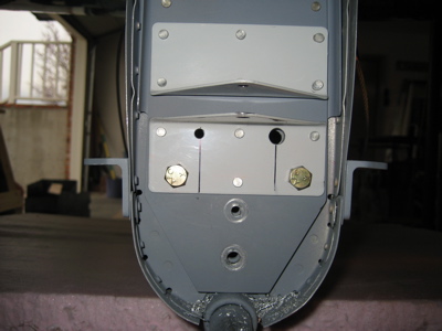
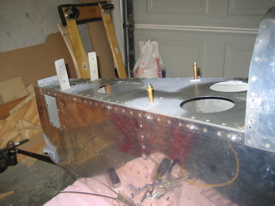
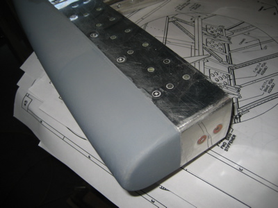
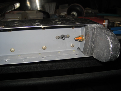
I decided on a new plan of attack for the elevator caps – I'll attach them permanently, but I'll make them look like they can come off. Then at least all the fairings on the tail of the airplane will have a consistent look, which is important if you're obsessive like me. First I rounded off the forward edges of the lead counterweight with a file, then I match drilled the untouched elevator cap and installed nutplates and reinforcement strips:

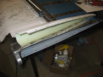
The two nutplates at the aft end are very close together. If I hadn't been forced to use the prepunched holes I would have staggered these a bit to avoid interference, as I did with the aftmost rivets holding the aluminum strips to the fairing. As it is I had to cut down some screws to keep one screw from trying to push the other one out.

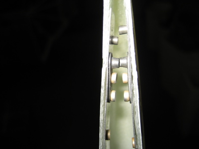
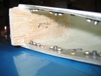
Here's another thing that I'll do differently on my next airplane – when you dimple the attachment holes for the elevator caps, the rib flange gets between the dimple die and the skin and all your dimples end up with this little crease on the inboard side. You won't be able to see this once it's all painted, but if I'd known this I would have at least match drilled the fairings and dimpled these holes before riveting the elevators together.

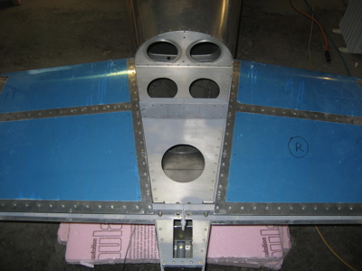
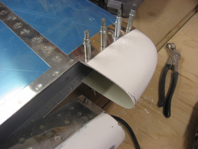
Here's a test fit to make sure all the nutplates and holes are lined up:

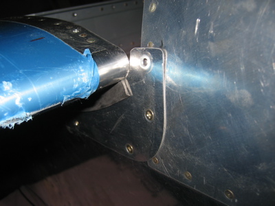
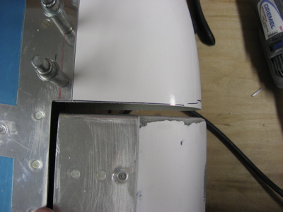
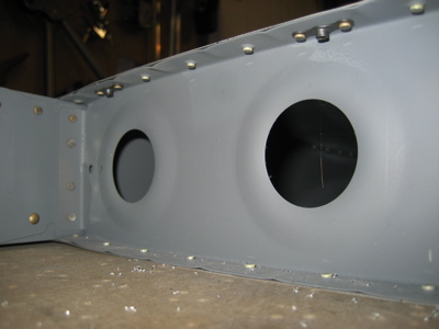
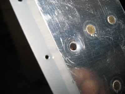
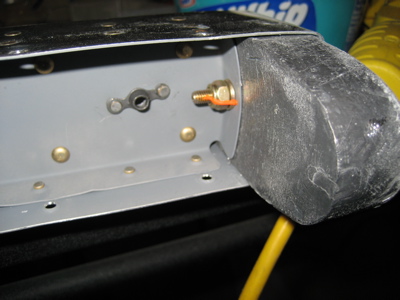
I riveted a #10 nutplate to the outboard side of the counterbalance arm, using the 3/16" tooling hole that was already there. The reason for putting a nutplate here is that I can use it to bolt on a wide-area washer or two if it turns out that my elevator needs a little bit more weight up front… call it balancing insurance. Also, this photo is proof that I checked the torque on the outboard counterweight bolt on the right elevator – it will be inaccessable once the fairing is on for good.

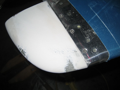
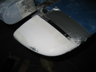
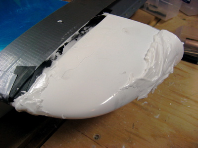
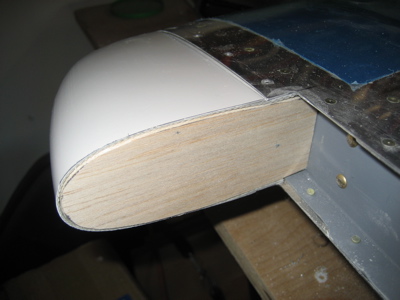
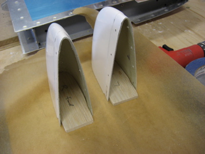
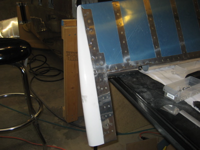
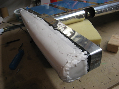
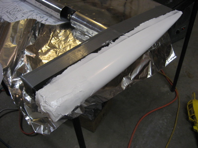
Okay, I wasn't able to take pictures of how I performed the next series of steps, but I'll describe it and show the result. I mixed up a slurry of epoxy and flox, and applied a thick layer between the lead counterweight and the inside face of the tip fairing. This should glue the fairing to the lead and also fill in the gaps between them. Then I put in all the screws, and covered the edge of the skin with a layer of electrical tape. Next I mixed up a big batch of epoxy and micro, and used it to fill the gap between the skin and fairing on both sides of the elevator. I also applied a generous helping of filler to cover over the forward face of the counterweight, and the corners with the fairing and the counterweight come together. Most of it will get sanded off later, but this should hopefully provide the basis for a nice looking fairing closeout.

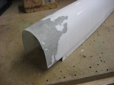
After all of the above was finished, I figured the right elevator would be out of commission for the rest of the day before the goo was cured, so I started thinking about the left elevator. It turns out that a replacement elevator cap is thirty bucks from Van's, so instead of throwing away the one I'd previously tried to put glass on, I spend some time sanding off my mistakes and restoring it to nearly-new condition.

Then I performed the same series of steps – match drilling, installing nutplates, and so forth. This photo is proof that I installed the spare nutplate and checked the torque on the inaccessable bolt on the left elevator

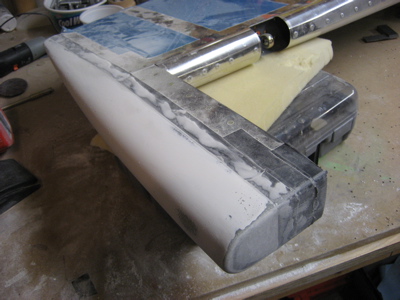
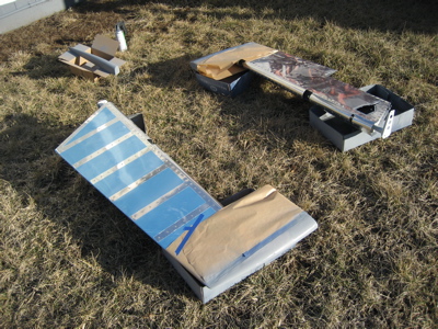
After all that (a couple hours of work) the left elevator cap got the same filler treatment:

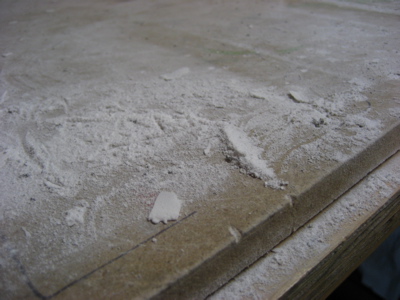
Once both elevators are dry I'll start sanding them down. For now, though, I'm sick of composites.