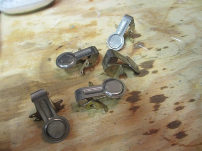
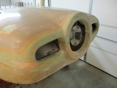
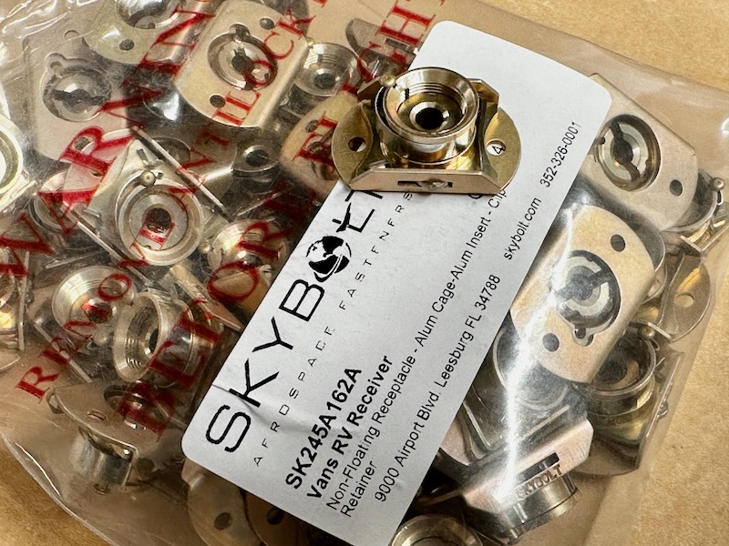
I have been putting off finishing the cowl fasteners for no good reason, so I decided to tackle this job at last. I am using the standard hinges on the vertical portions of the lower cowl at the firewall, machine screws behind the spinner, and Skybolt quarter-turn fasteners everywhere else. In total I needed 42 sets of studs and receptacles to attach my cowl:
I put the cowl on the airplane, made sure everything was still fitting well, and drilled the existing pilot holes up to #30:
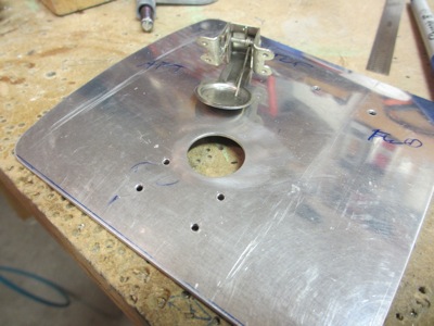
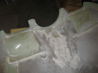
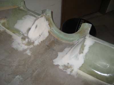
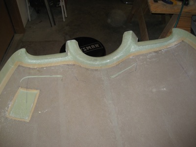
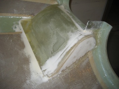
Then I removed the upper flanges from the firewall, and used the provided templates to drill all the required holes. Drilling the center holes from #30 to 11/16" with the unibit generated a tremendous amount of shavings, and required some concentration to keep the bit from wandering off-center:
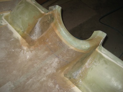
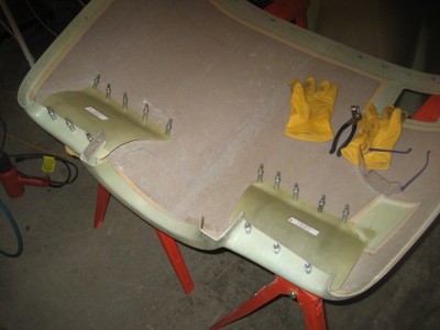
After preparing the flanges, I riveted everything to the firewall. Afterwards I realized that this might be the very last structural riveting of the whole project… sure there will be additional rivets for nutplates and so forth, but I think this is the last bit of primary structure that was still left un-riveted.
Due to the limited space available in places, I chose to attach the Skybolt receptacles to the flanges with countersunk blind rivets:
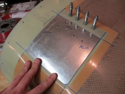
Back to the upper cowl, I drilled the #30 pilot holes along the aft edge up to 15/32", again watching to make sure the unibit didn't wander:
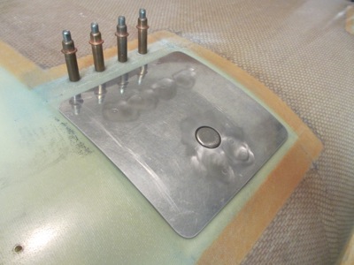
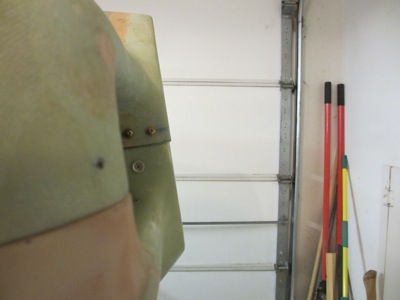
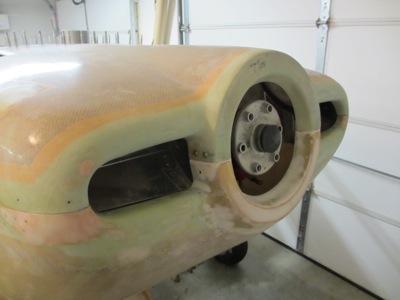
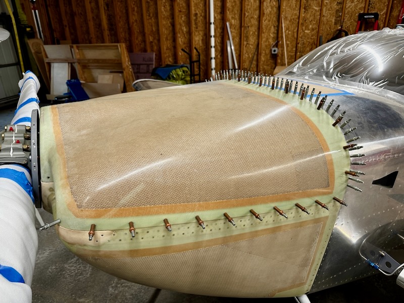
After installing the studs and grommets in the upper cowl, I did a test fit and was happy to see that I had everything lining up well so far:
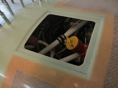
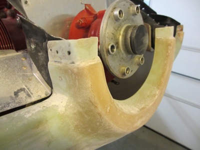
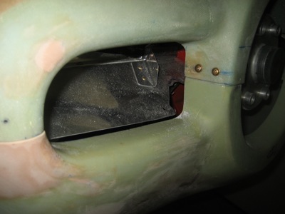
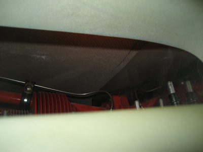
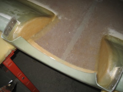
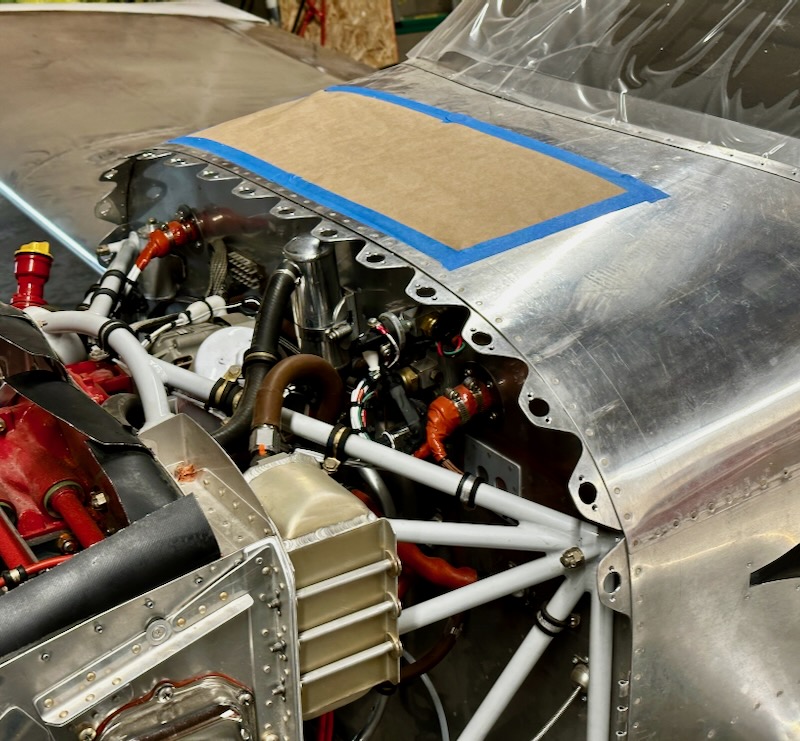
Since the mounting flanges along the bottom of the lower cowl were already riveted to the firewall, I had to drill the holes in-place:
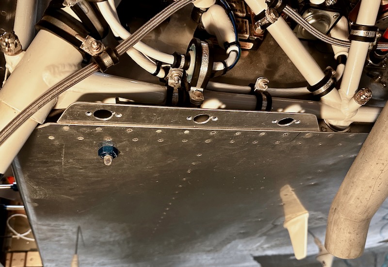
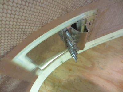
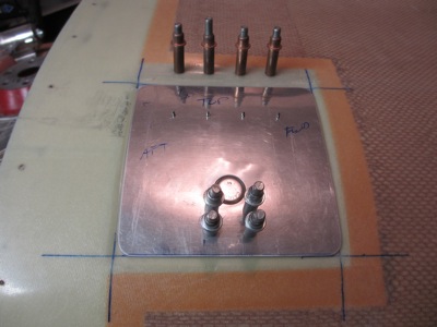
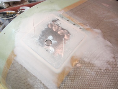
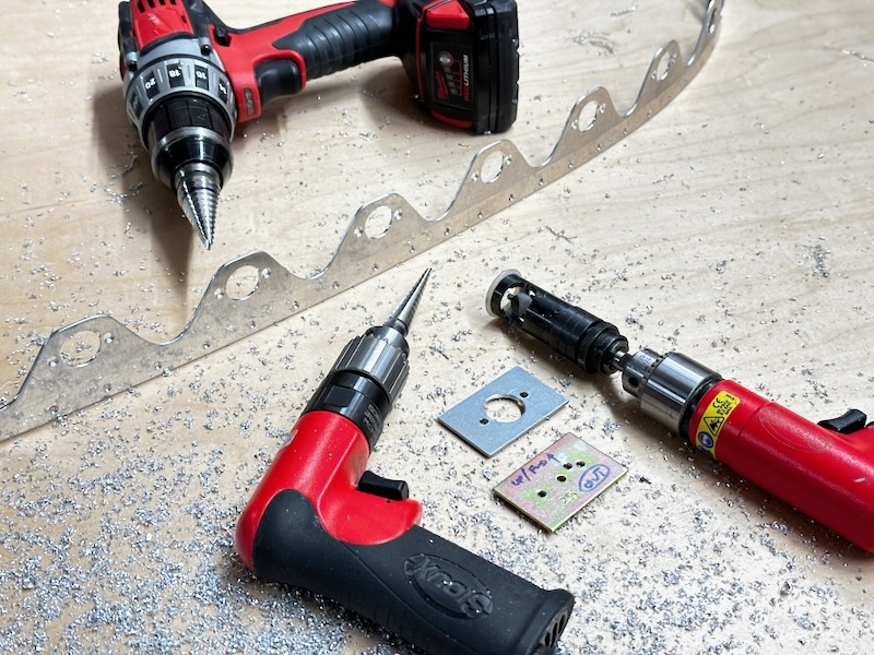
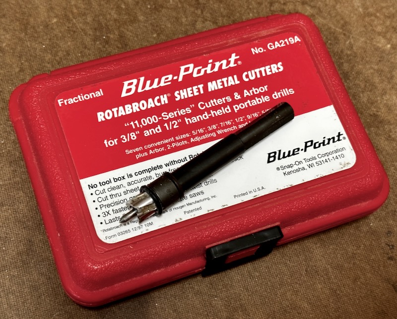
To avoid drilling through the engine mount or various nearby components, I made the above holes using a 5/8" Rotabroach cutter, with a washer and a rubber o-ring acting as a makeshift drill stop:
Using the Rotabroach cutter for the bottom flange holes gave me an idea for a better way to drill the holes in the fiberglass cowl. Instead of separately drilling the holes in the cowl and the underlying flange and then hoping they line up, I realized that I actually had a way to make these holes perfectly concentric.
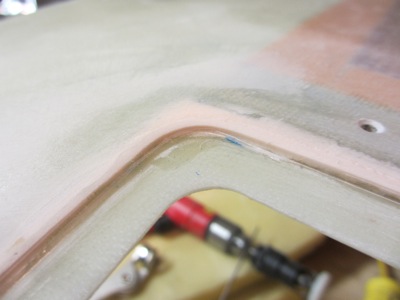
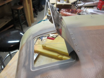
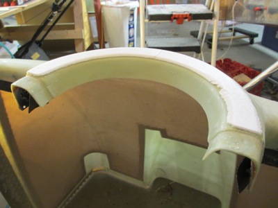
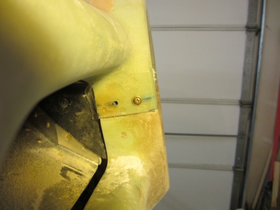
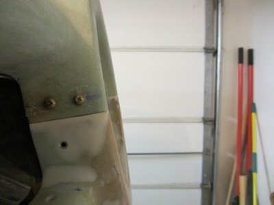
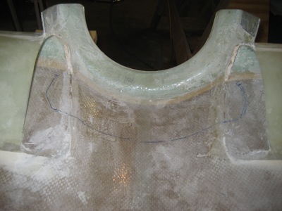
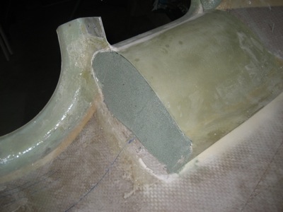
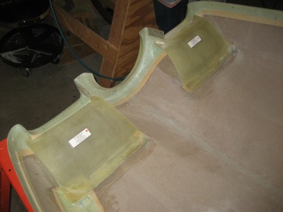
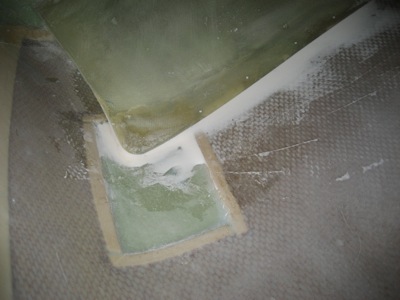
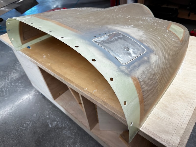
On the cowl side flanges, I used the Skybolt template to drill the #30 holes for the rivets and lock pin, but I left the center hole at #30:
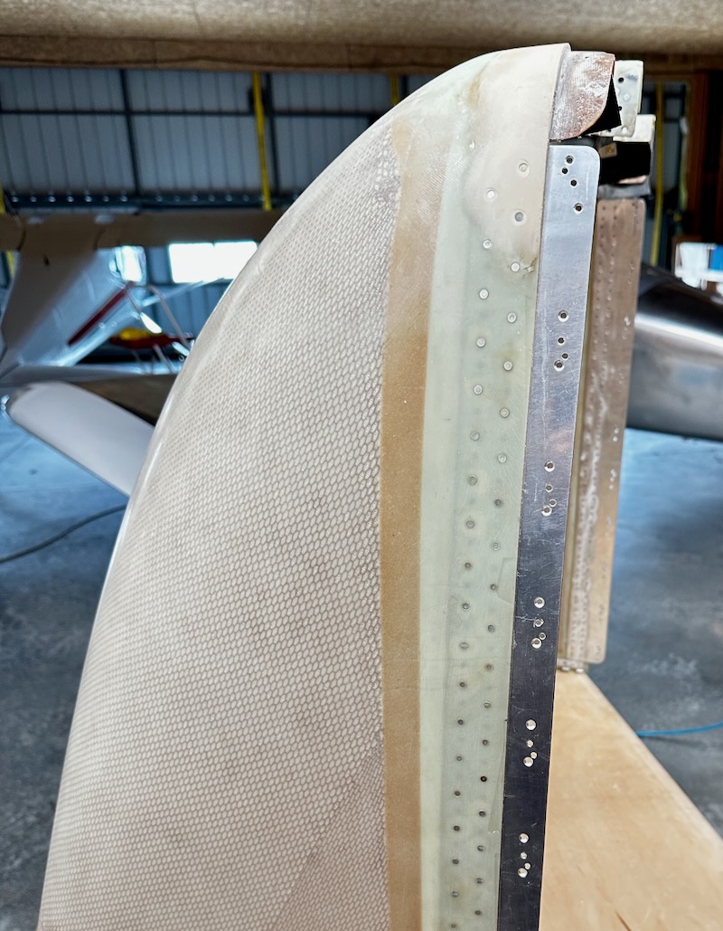
(yes I realize the edge distance is not great at the front, but it's too late to extend these flanges now)
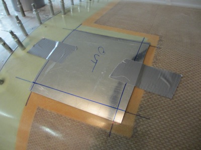
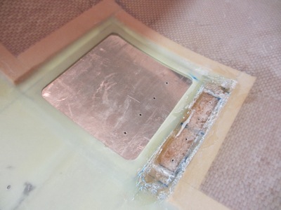
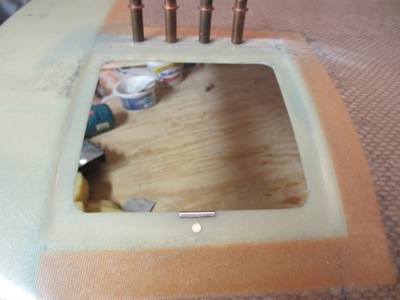
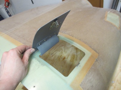
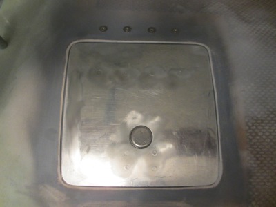
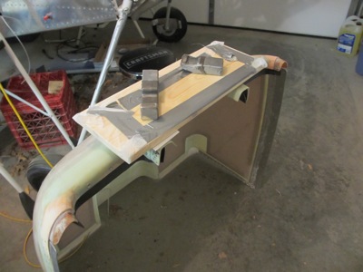
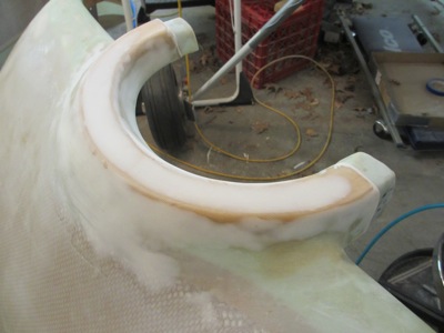
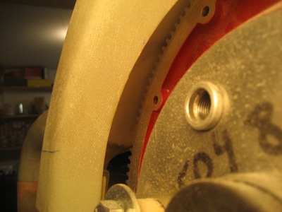
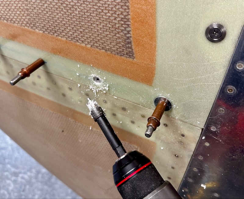
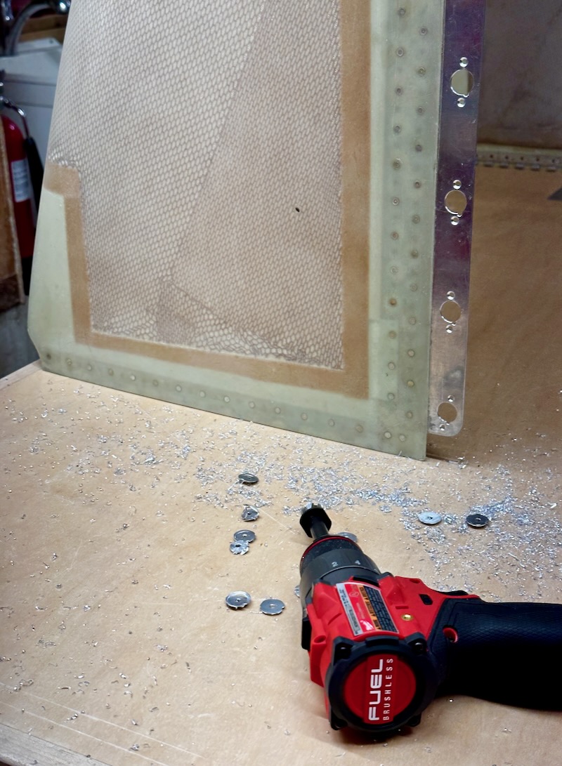
Here's the entire process in one image: I installed the cowl with clecoes, then removed one cleco, cut through the fiberglass using the ejector pin on the Roatabroach as a pilot, and replaced the cleco with a 1/8" fender washer underneath. Repeating this process for every fastener location gave me a row of perfectly-placed holes in the cowl, even where the holes in the fiberglass were wonky or buggered up.
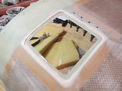
The Skybolt grommets require a 15/32" hole and the closest Rotabroach cutter I have is 7/16", so I cut all these holes slightly undersized in-place and then enlarged them the last 1/32" on the workbench with a unibit. Then I removed the lower cowl and used a 5/8" Rotabroach cutter to make the holes in the flanges for the receptacles:
Doing it this way guarantees concentric holes, since you're using the same pilot hole to guide the cutter in both cases… really a special kind of match-drilling.
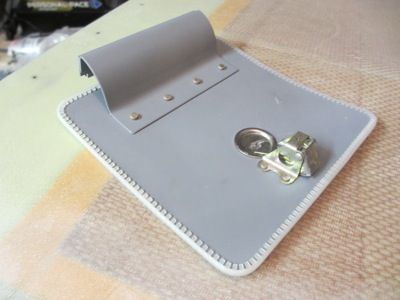
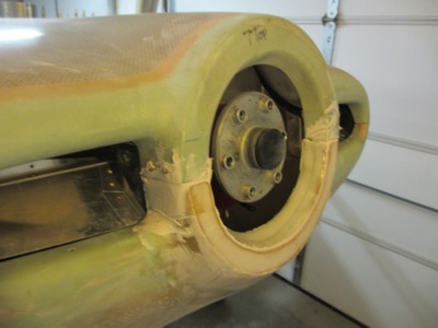
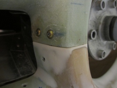
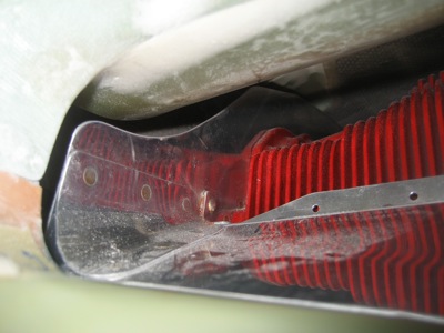
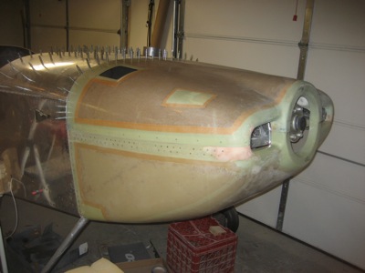
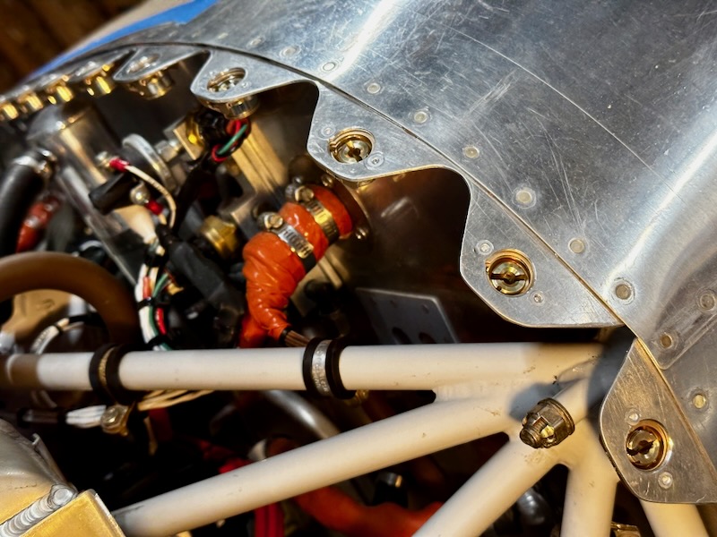
After deburring everything, I riveted the remaining receptacles to the lower cowl, and installed it back on the airplane:
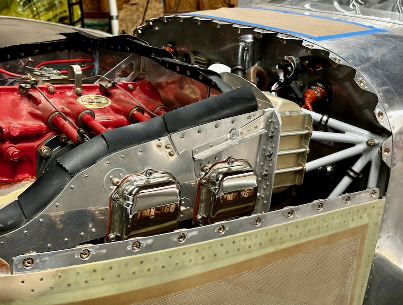
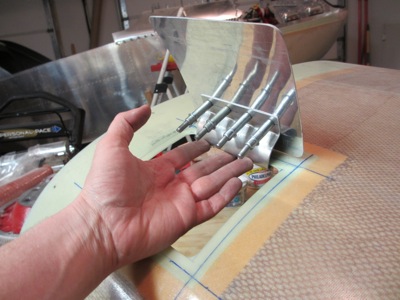
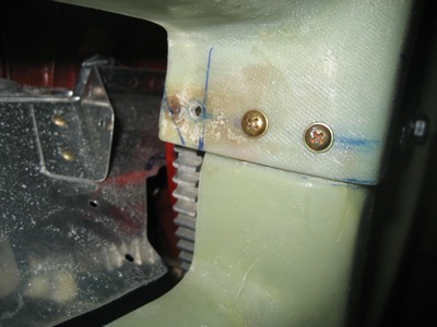
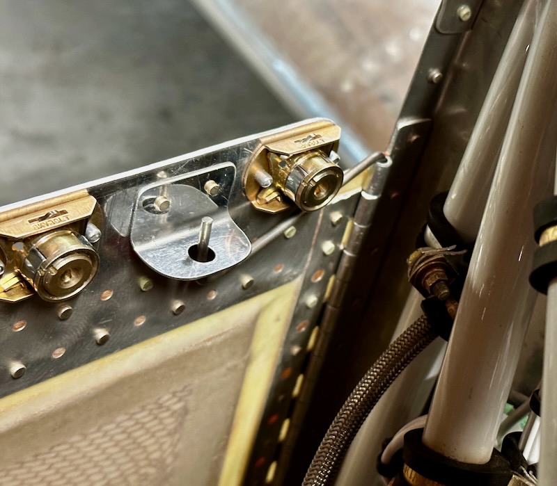
And sure enough, every one of my fastener studs engages perfectly with its receptacle:
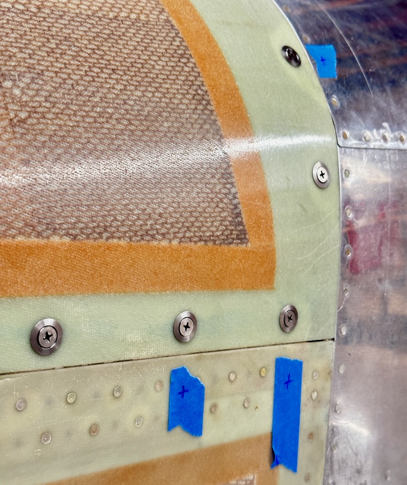
Adjusting the depth of the receptacle inserts takes some trial and error. You have to install the cowl, mark the ones that are too high or too low, remove the cowl, unclip and adjust each receptacle, and repeat. Each half-turn of a receptacle adjusts the depth by 1/64", so although you can't get every one perfectly flush, you can get pretty close:
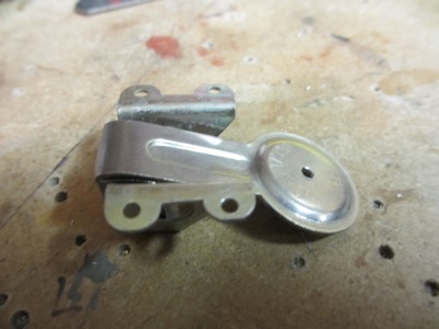
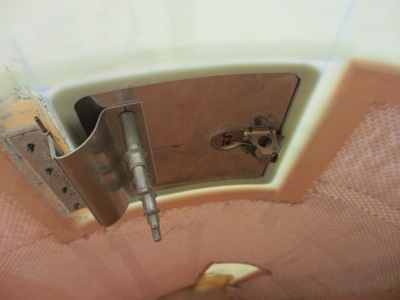
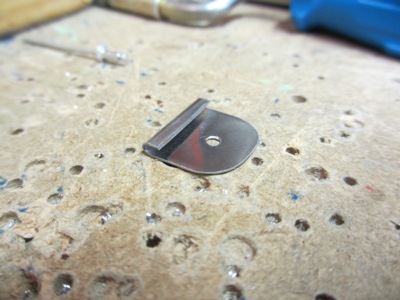
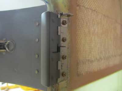
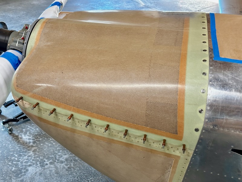
After finishing the Skybolt fasteners, I bent the ends of the lower cowl hinge pins upwards, and riveted these little clips to the inside of the cowl flanges. Now the pins are secured from rotating or backing out, but they can easily be sprung loose when required:
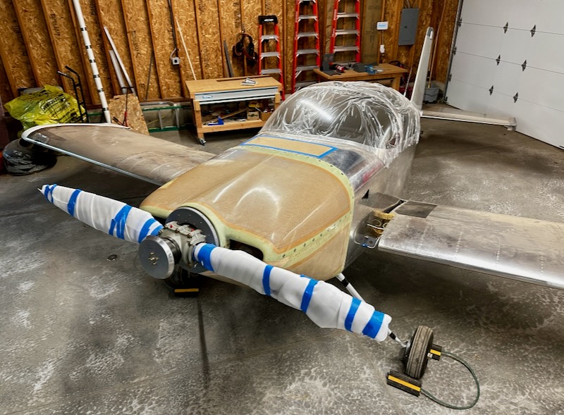
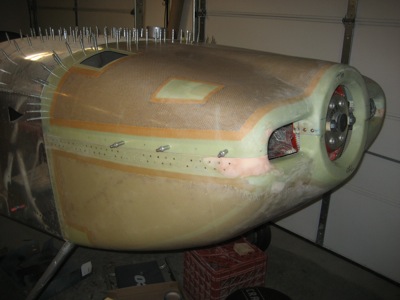
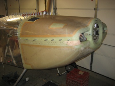
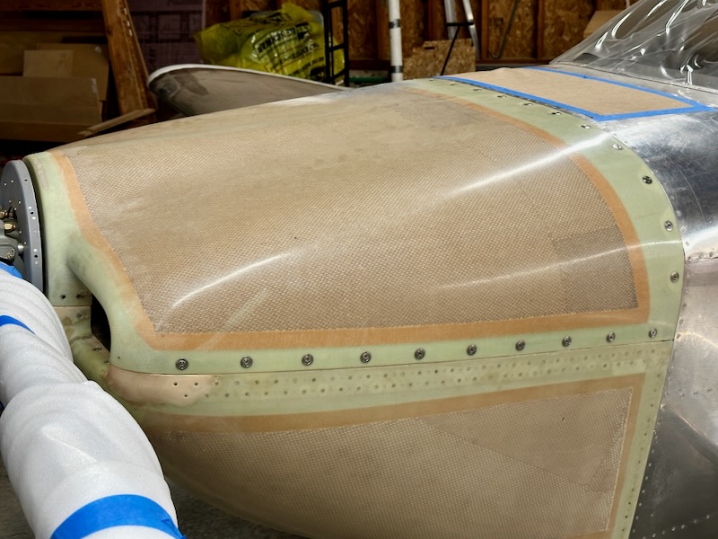
The airplane looks pretty good with the cowl attached. I still have some minor fiberglass work to do, but that job will wait for a future work session: