Hello, is this thing on? And is anyone still reading? Anyway, here are the highlights of the past almost-five-years since I last updated this blog…
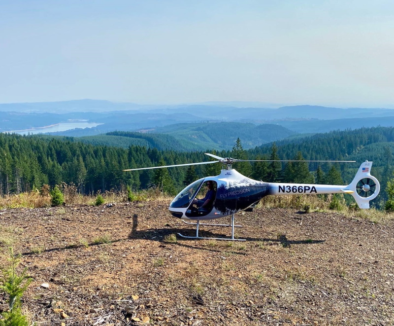
We moved to from Kansas to the Pacific Northwest:

Still married to this girl, who is still the best:

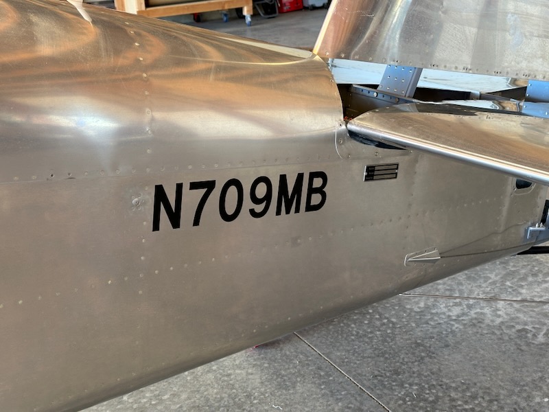
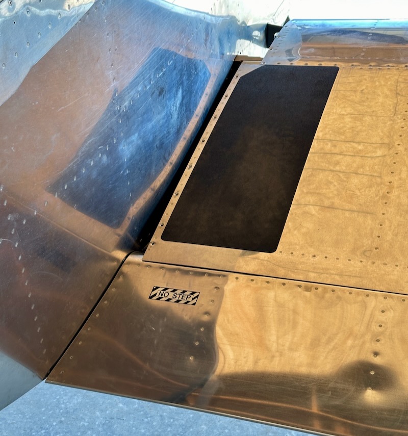
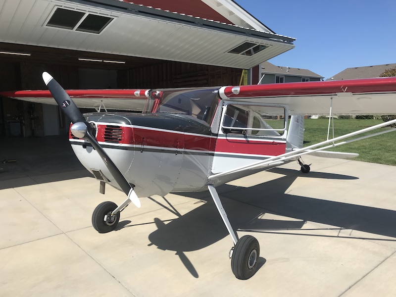
The above photos feature this 1946 Cessna 140, which I now co-own with a local friend:
I did a ton of skiing, since I now live close to tall mountains:

We adopted this cat, who is great:

I got into scuba diving, achieved my master diver card, traveled to some amazing places, and made some cool friends doing it:


We built a house:
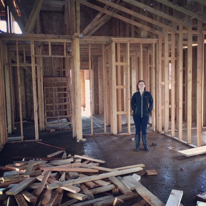
It's on a residential airpark and has a hangar attached:
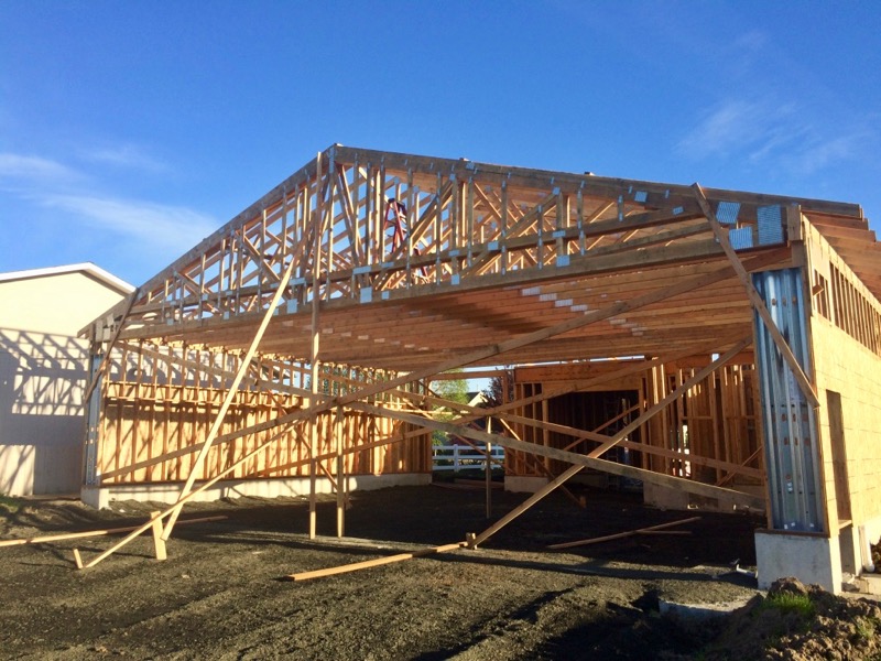
Should be room for two airplanes in here if I'm careful – though it isn't this empty anymore, sadly:
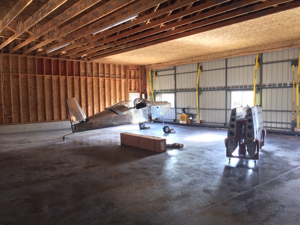
It's amazing how quickly a seemingly limitless amount of "stuff" accumulates overnight in a space like this. I anticipated this would happen, so I designed in a roughtly 10'x20' area at the back of the hangar to be used as a separate workshop or toolroom annex. That should at least help keep the tools and projects from totally overrunning the main part of the hangar and crowding out the airplanes.
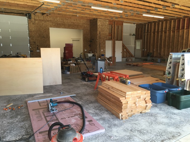
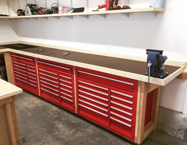
Since this is a brand-new house, I had to start from scratch and bootstrap my way into a functioning workshop. First, since I can never have enough room for tool storage, I bought three big rolling steel toolboxes on sale from Harbor Freight.
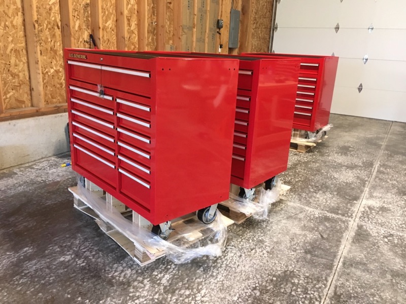
Yes, "Harbor Fright"… look, I'll be the first to agree that a lot of their products are junk, but these particular toolboxes are actually really nice for the money. They're certainly higher quality than modern Craftsman units, which in my experience have really become bottom-of-the-barrel products.
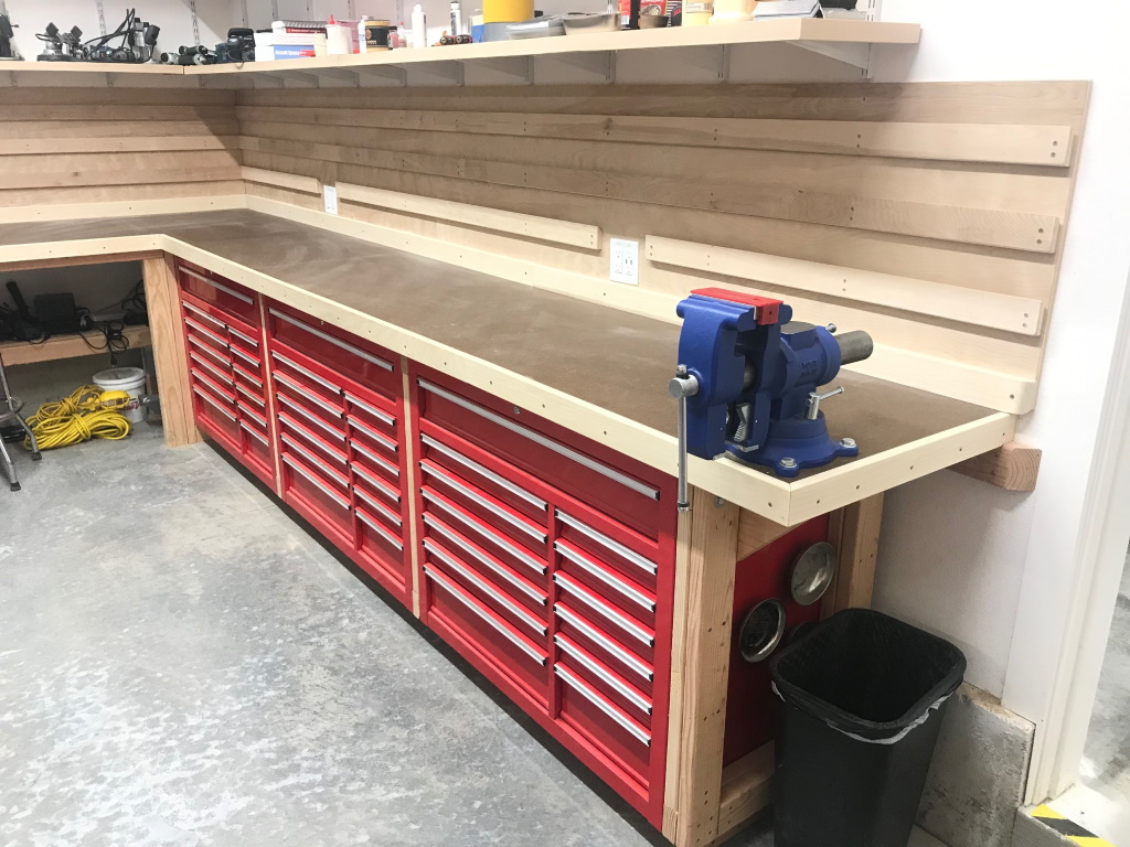
I removed the wheels from the toolboxes, and built a 2×4 frame that surrounds them. The frame is attached to the wall studs and the toolboxes are bolted to the frame. There's a toe kick underneath, so the end result is that the tooboxes are now similar to a row of oversized kitchen base cabinets.
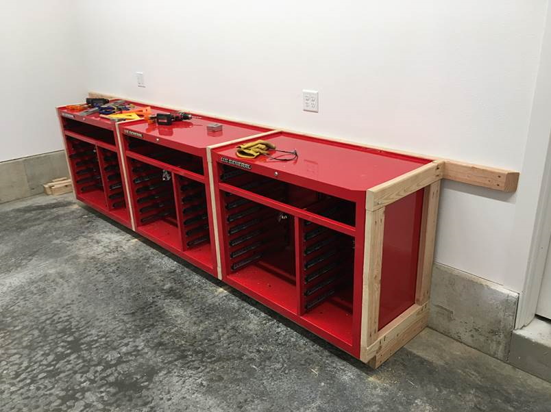
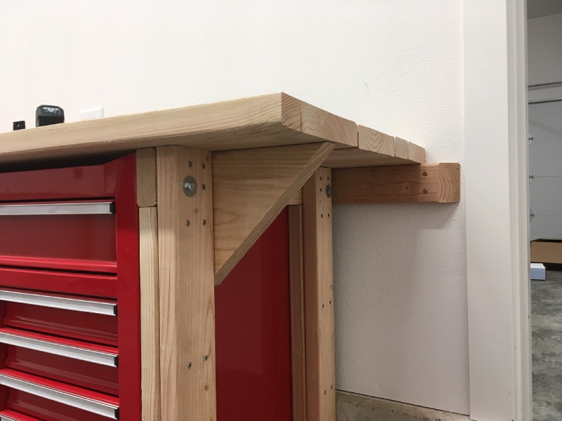
On top of the workbench frame I built a sub-surface made of the straightest two-by lumber I could find, laid sideways. This corner is reinforced to support a bench vise:
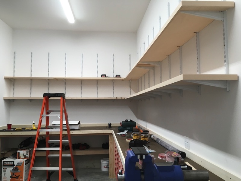
The workbench continues to the left, wraps around the corner, and goes all the way across the end wall:
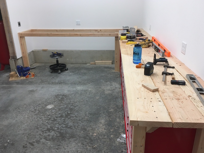
The framework of this half is more or less basic EAA 1000 style construction, again fixed to the wall studs:

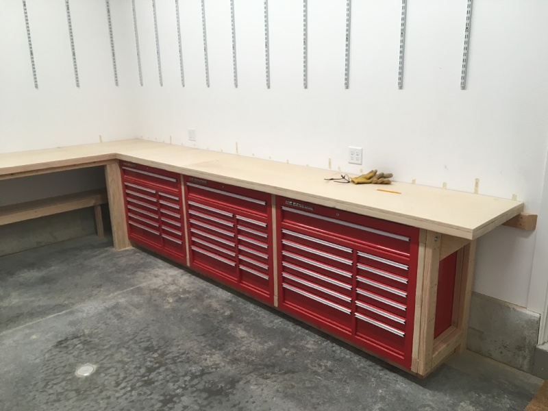
On top of all this I attached a layer of 3/4" birch plywood:
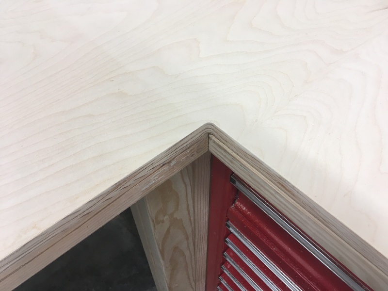
I used a handheld router to put a nice radius on the inside corner:
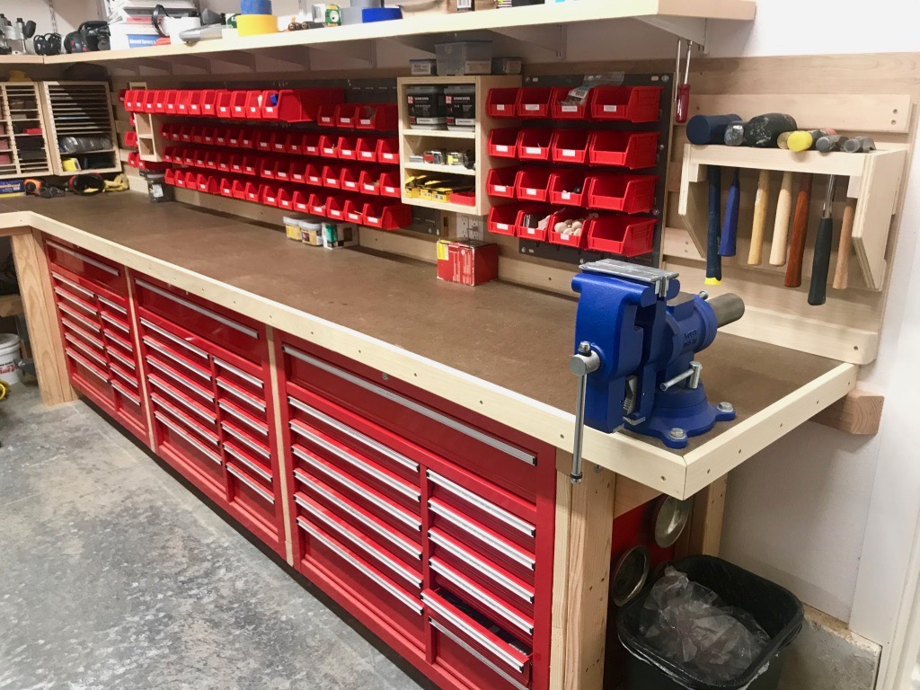
I dressed up the workbench with some hardwood trim, and covered the top with a sacrificial layer of 1/4" hardboard (aka masonite) to give a smooth surface. On the right side I mounted a 5" Yost pivoting vise.
Above all this I installed some steel shelf standards and built some storage shelves. I like having this storage but in retrospect I don't think I'd use this method again, since these components are kind of expensive and difficult to work with for long shelves like these. It took a lot of fiddling to get the support brackets to all line up properly.
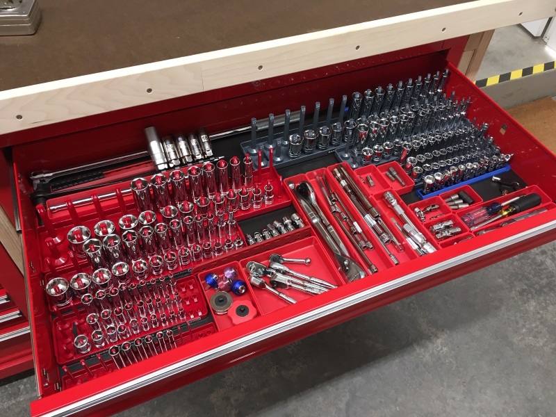
Inside the drawers I went nuts with tool organization. Sockets:
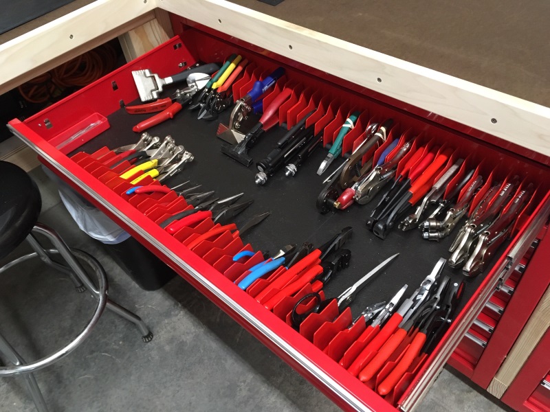
Pliers:
Wrenches etc:
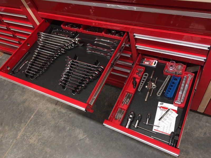
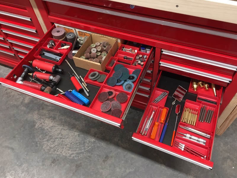
Just a whole lot of tools:
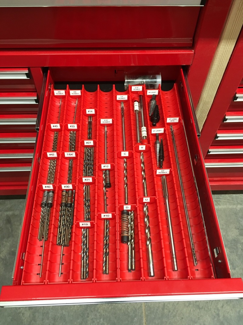
These Lista trays are my new method for drill bit organization:
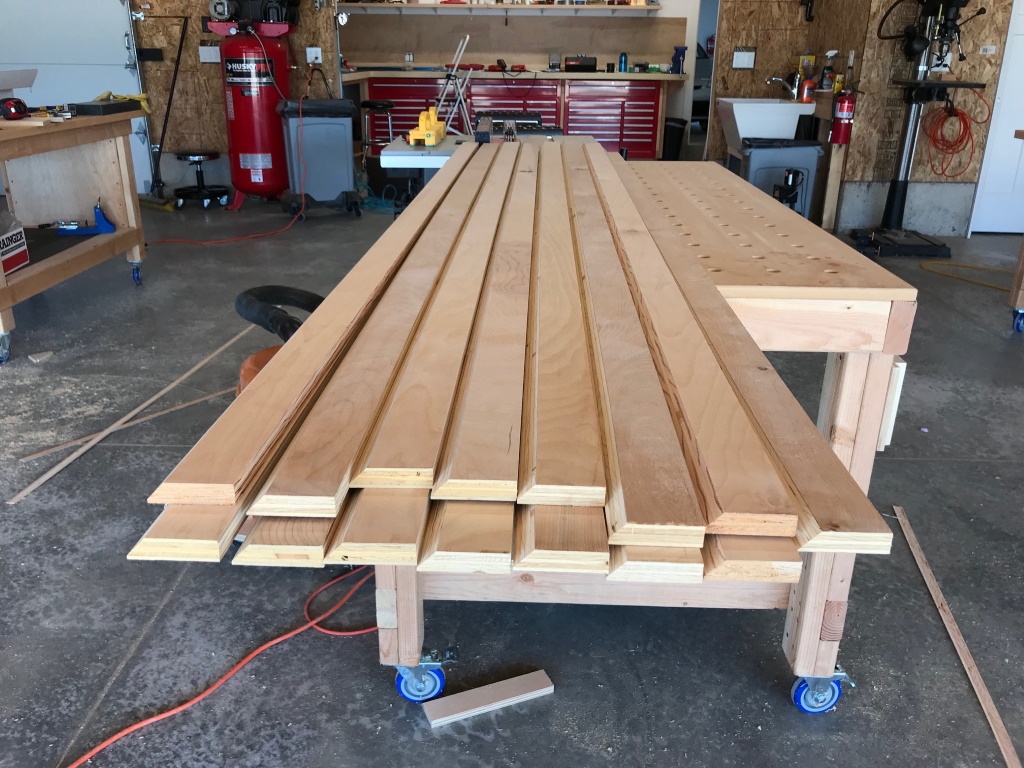
I also built a couple of EAA 1000 type workbenches, in the usual fashion:

I've built enough of these things over the years that I can practically do it in my sleep, but nowadays my technique has evolved somewhat. I make the top surface out of two sheets of 3/4" plywood laminated together, and I trim the edges with hardwood to dress it up a bit. It comes out looking great and it's really not hard to do.
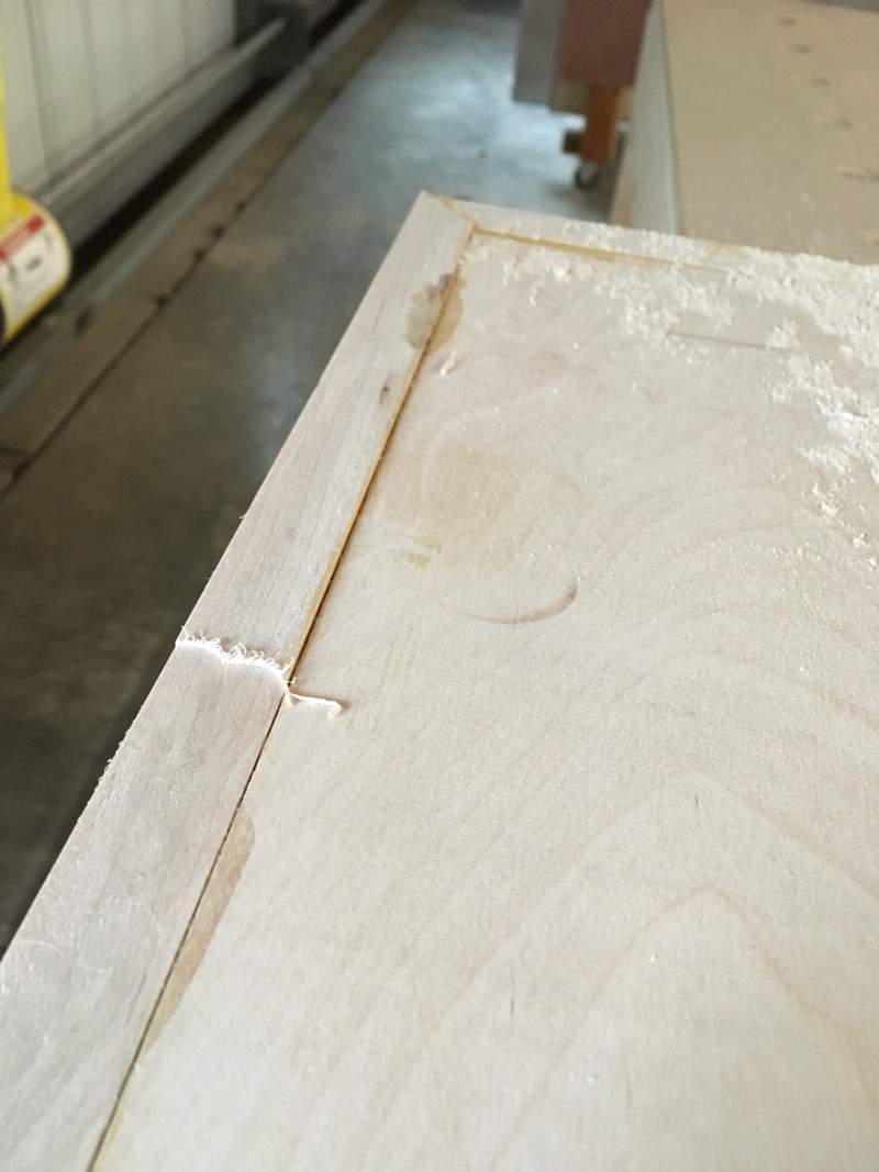
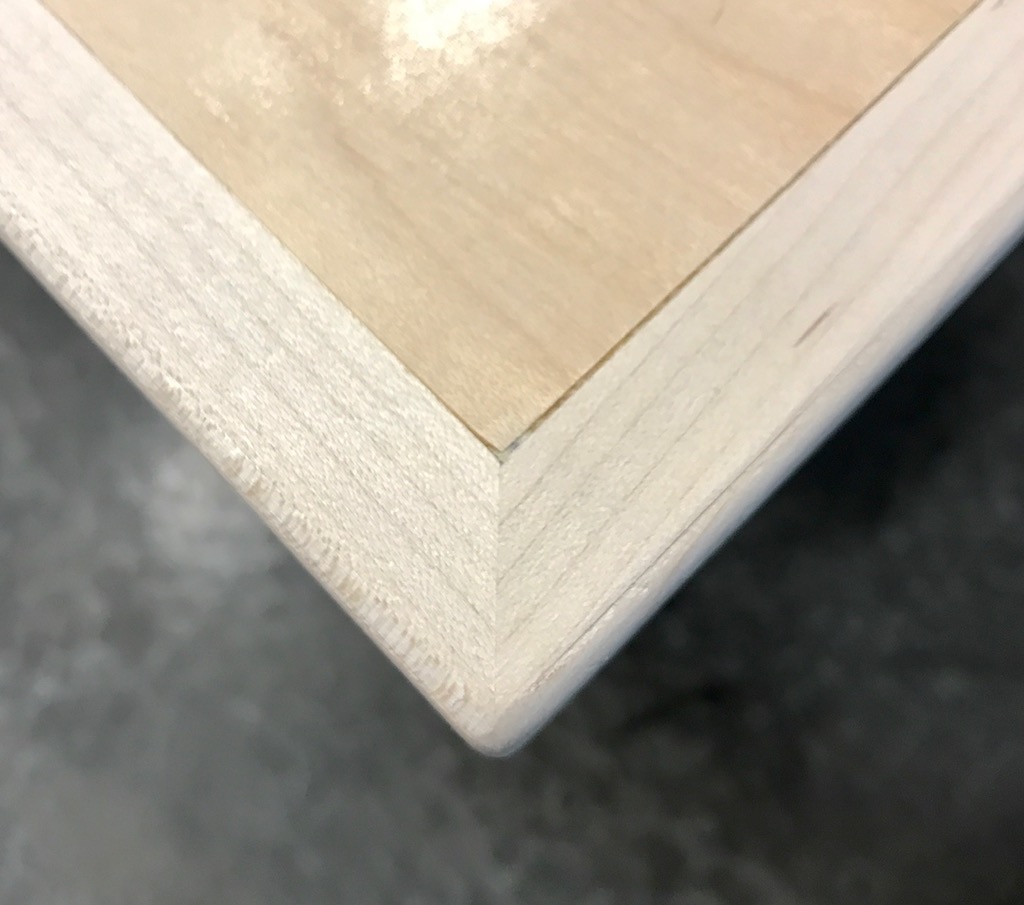
First I miter the corners of the trim, attach it to the edges of the plywood with glue and pin nails, and clamp it until the glue dries. The big-box stores sell 1.5" x 3/4" hardwood sticks which are perfect for this. Poplar and maple are both good material choices.
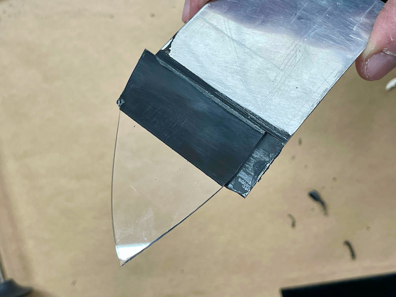
Then I use this simple jig in a small trim router to shave down the edging until it's almost level with the plywood surface. Use a straight bit and set the height to just a few thousands shy of the surface, say about the thickness of a piece of paper.
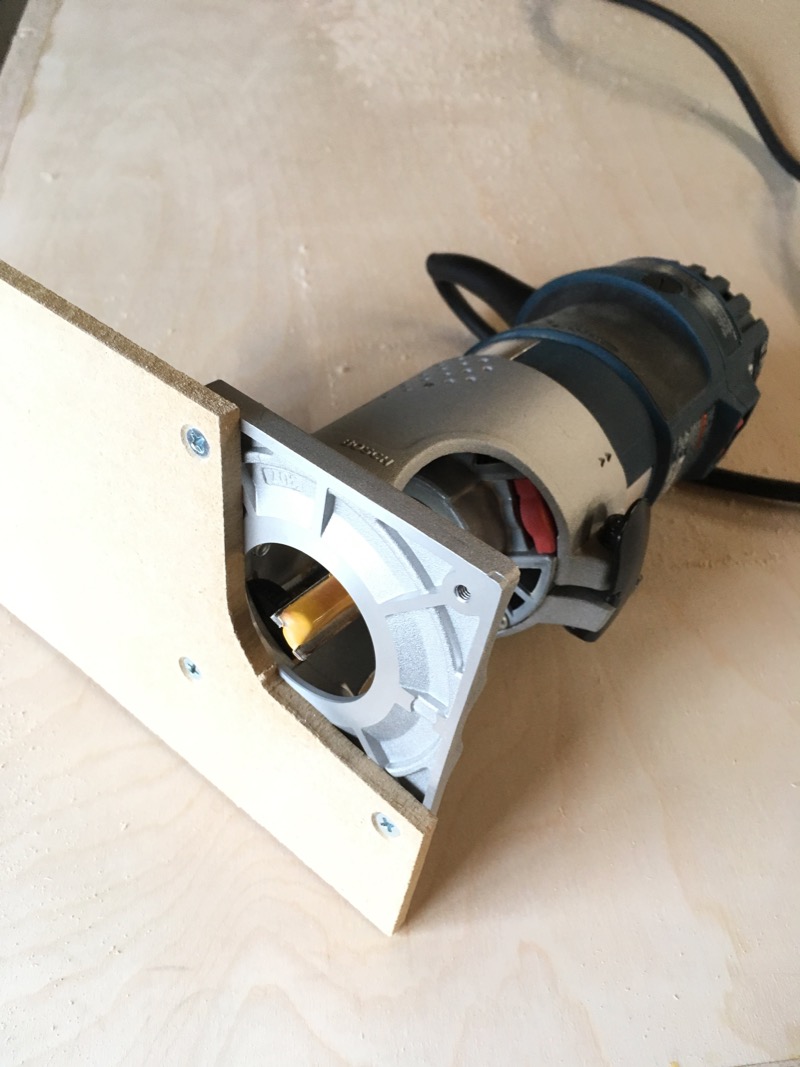
With this you can quickly remove the excess, leaving the trim protruding just a little bit above the surface:
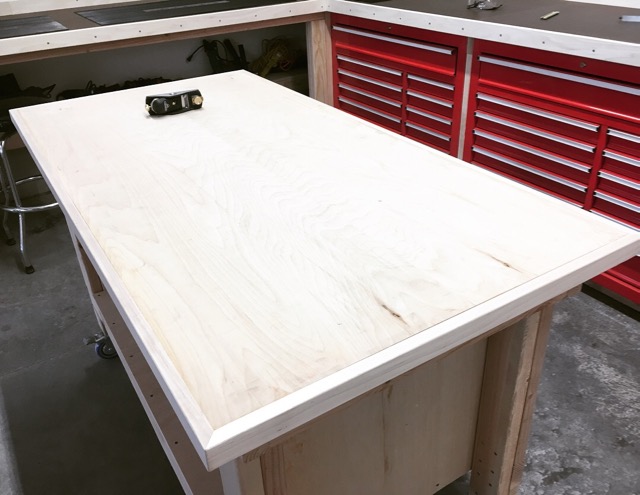
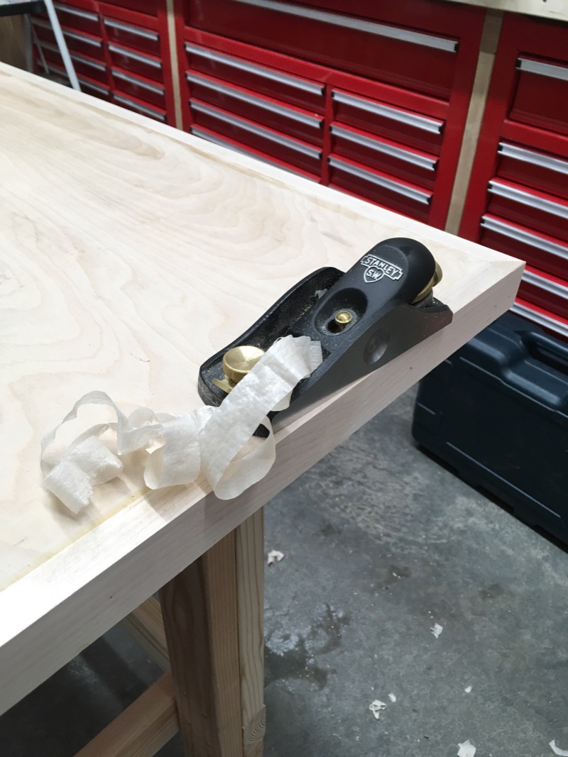
Then I use a hand plane (this is a Stanley 60 1/2 low angle block plane) to shave off the last few thousandths, which leaves a dead-flat and glassy smooth surface:
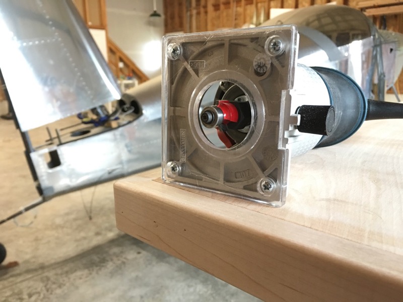
The last step is a quick pass with the trim router and a 1/8" roundover bit to soften the edges and corners:
With this method you can achieve really nice results, especially if you apply a coat or two of wipe-on polyurethane finish:
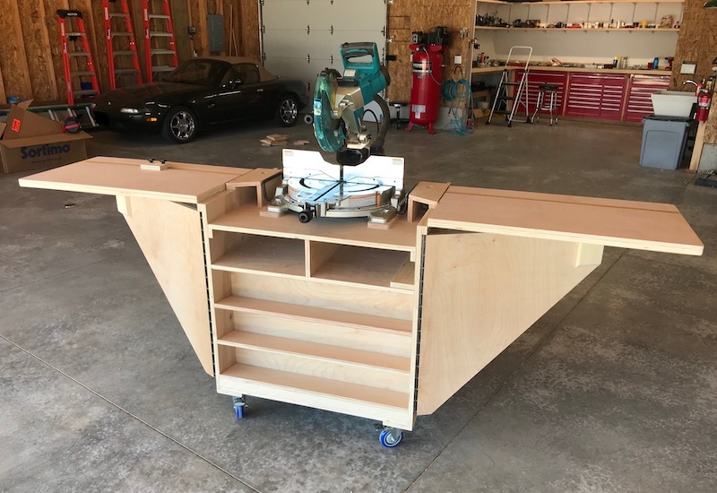
One of the new tools I bought was a miter saw, a tool I'd always wanted but never had room for up till now. Cutting lumber with the saw sitting on the floor was killing my knees, so I built this rolling stand for it:
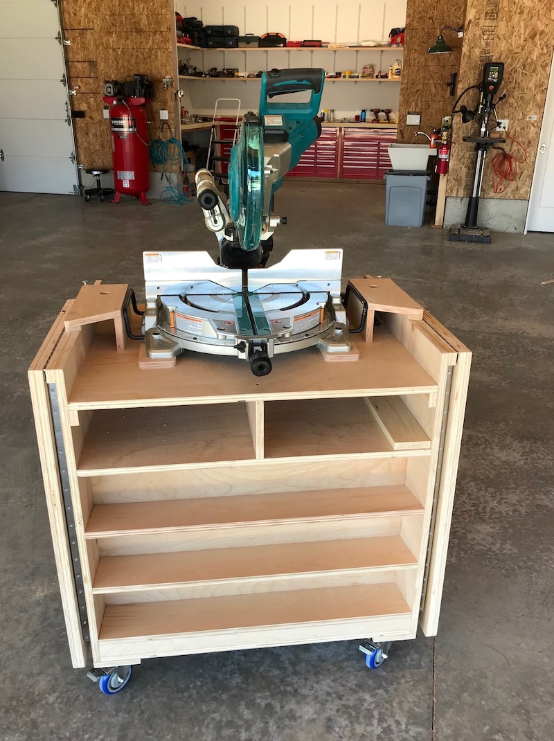
Construction is simple 3/4" plywood and pocket screws. It has fold-out extension wings for cutting long boards:
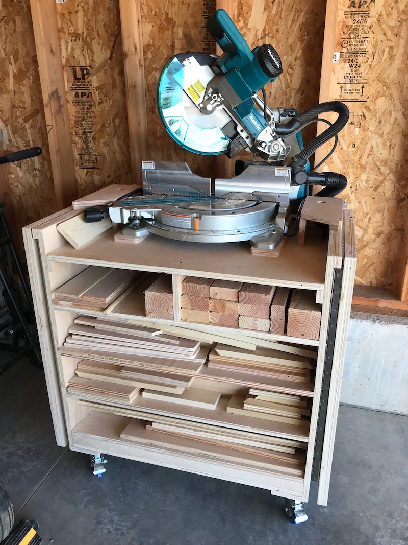
When not in use it folds up and rolls out of the way, and also doubles as storage for offcuts and useful scrap wood:
Another big tool I always wanted but never had room for is a router table. I still don't have frequent need for one, but it's one of those tools that makes certain jobs much easier. For this I built yet another workbench, this time mostly from plywood, and put a router plate and lift in one end.
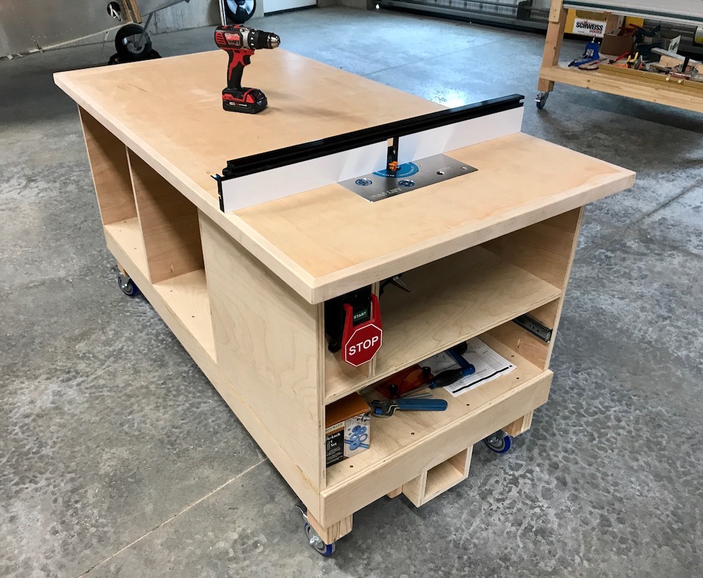
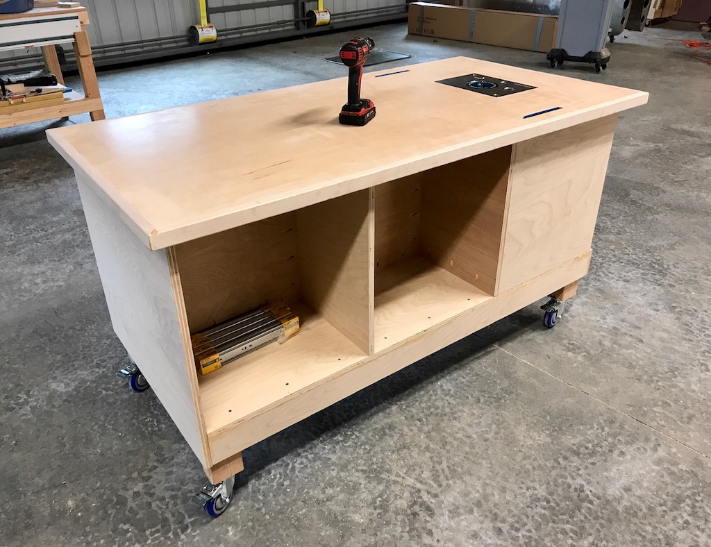
When not in use, the router drops down out of the way, the fence is stored underneath, and it becomes just another handy workbench:
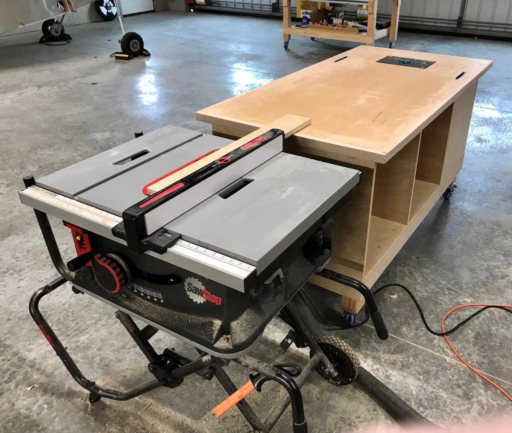
Speaking of handy, I've also been building these rolling workbenches to be the correct height to use as an outfeed table for my table saw… speaking of large tools I never had room for in the old house!
I'm still just an amateur woodworker, but it's been fun learning to use these new machines and tackling some more ambitious projects. I've done several projects for the inside of the house too.
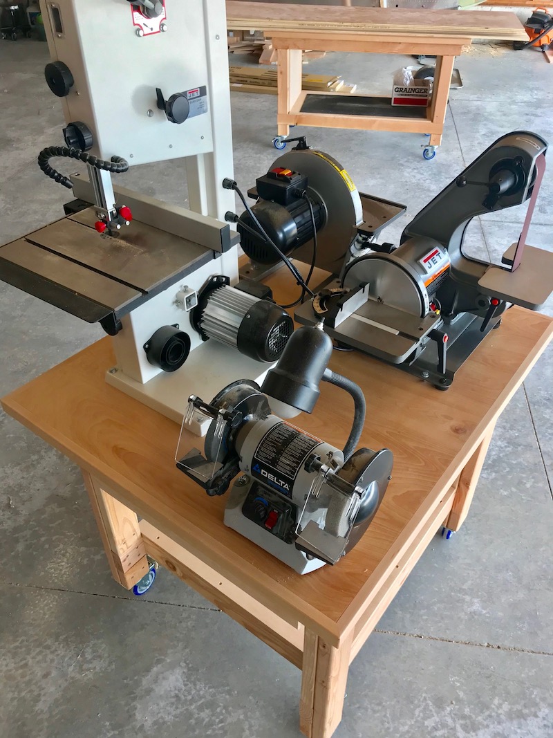
I didn't want any of my stationary power tools to be truly stationary if I could possibly help it, so I built this ~3'x3' rolling cart to hold four different small machines all at once:
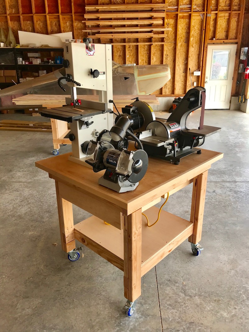
The bench grinder is the same unit I've had for ages, but the bandsaw, belt/disc sander, and 12" disc sander are all new acquisitions to replace my old worn-out machines.
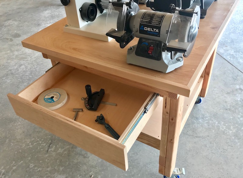
This cart has a couple drawers for storing attachments and accessories:
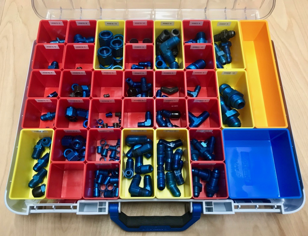
So much for tools, now for some parts storage. Twenty-plus years of owning, maintaining, and building (theoretically) airplanes has left me with a huge variety of aircraft hardware, and I was never happy with my previous organization method, which was those same plastic drawers and plastic boxes that everybody has. I wanted something that could hold a greater quantity of small parts in less total volume, but which would also be more flexible to handle oversized parts.
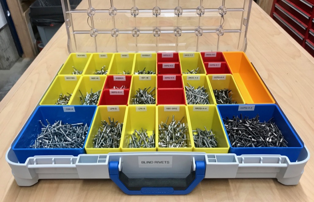
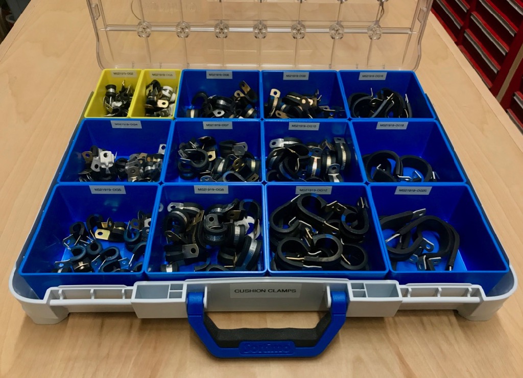
I settled on Sortimo T-Boxes, which I was tipped to by an Adam Savage video. These are neat because the inserts come in different sizes and shapes, which you can combine and rearrange as required. The lids are also very secure, and there are interior features to prevent parts from migrating from one container to another. Overall they're really nicely-designed products. The whole system is not exactly cheap, but I view it as an investment in my sanity and productivity.
So I spent a couple weeks' worth of evenings moving all the aircraft parts from their previously haphazardly-organized homes into shiny new Sortimo containers:
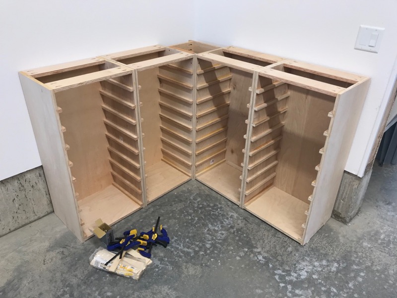
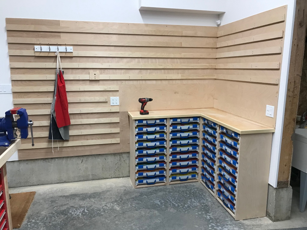
Then I built some sturdy cabinets in the unused corner of the workshop to keep all these things in… and yes, for those paying attention to the woodworking, this was an incredible number of dado cuts:
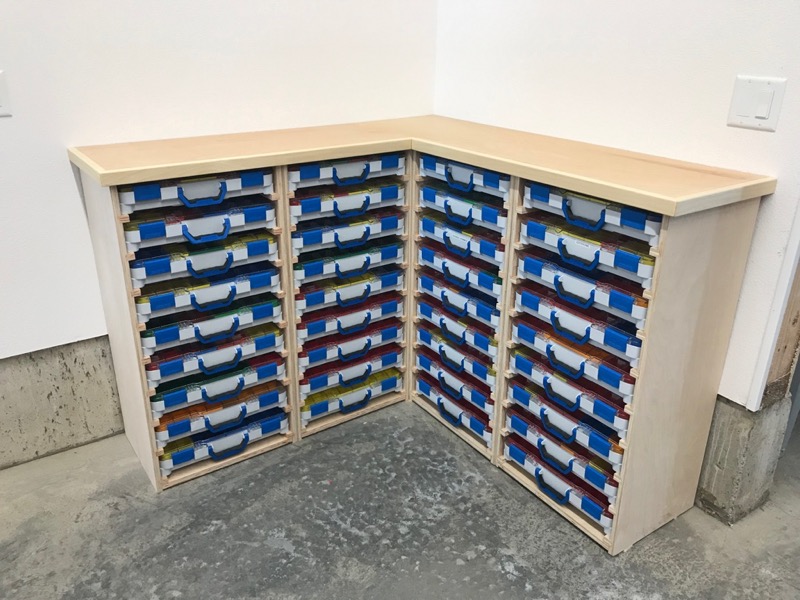
I built another tabletop using my usual method, and voila, a "chest of drawers" full of hardware:
Next, more wall storage. I had some leftover 1/2" cabinet plywood, so I used it to put up wall paneling in the workshop, in true groovy 1970's style.
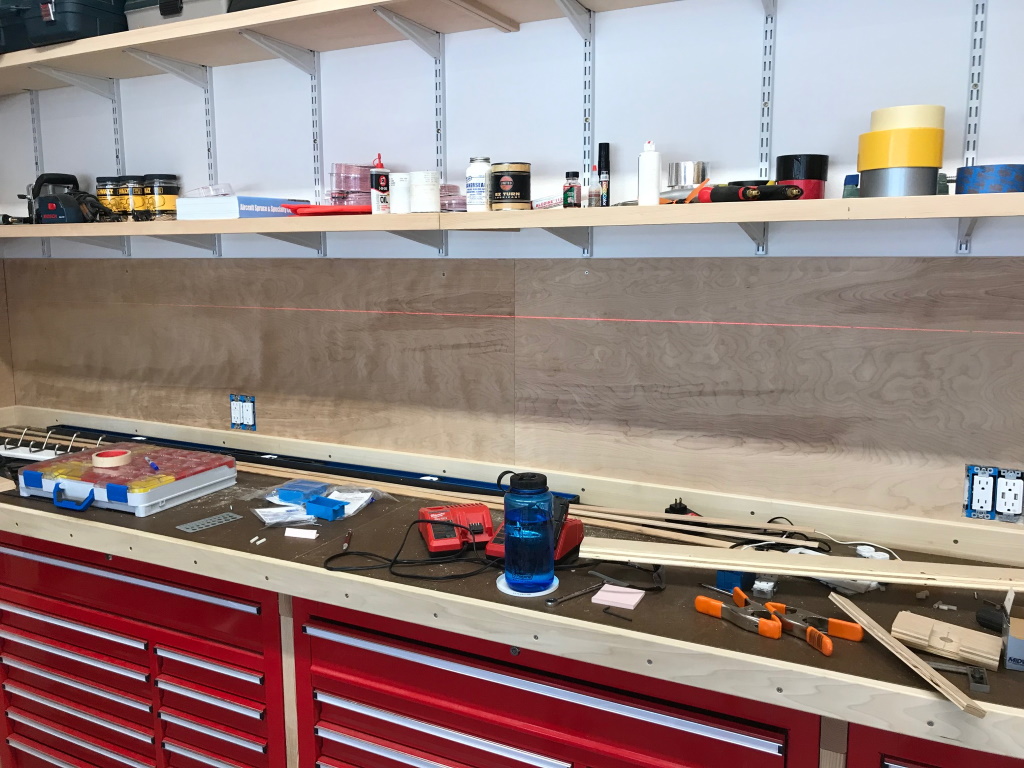
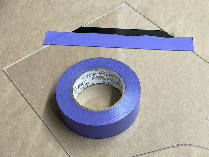
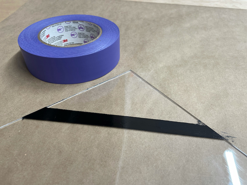
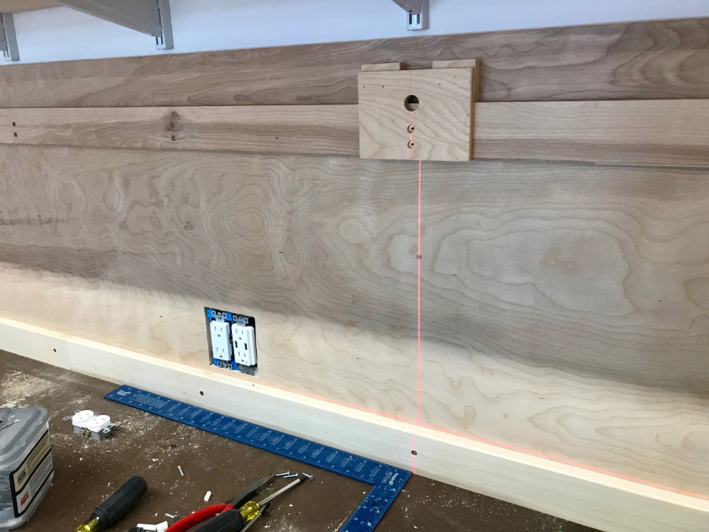
I used the table saw to cut a bunch of cleats out of 3/4" ply, each with a 45º bevel on one edge:
With a homemade jig and a laser level, I attached these cleats to the wall studs at regular intervals:
This is what it looks like when finished. This is called a French cleat system, and turns your wall into a modular hanging scheme for whatever you want to put on it:
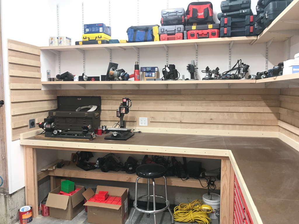
The other wall got the same treatment, just taller:
I built brackets and things on which to hang all the remaining tools that didn't have a good home yet. Nothing here is permanently attached to the wall, which makes rearranging the shop walls is a snap. I've already moved things around several times to get a more efficient layout, so I'm glad I went to the trouble of doing it this way.
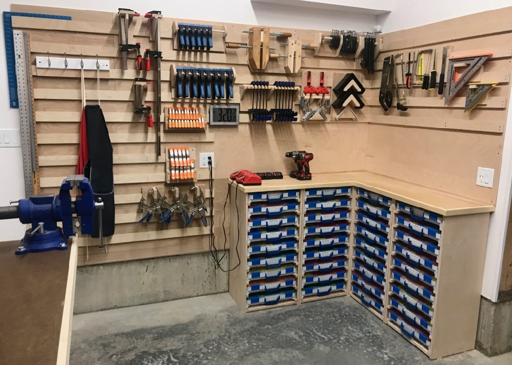
Wall O' Clamps:
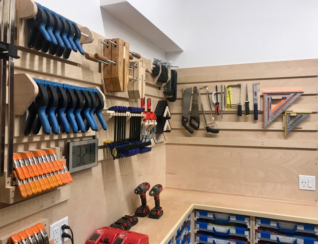
It was actually fun to build all these little tool hangers out of scrap wood. Plus it pleases my OCD to look at it.

The back wall is mostly plastic hanging bins containing non-aircraft hardware like nails and wood screws, plus a couple of small shelving units where I didn't want to cover over existing electrical outlets. I also built a simple hammer rack which lives behind the vise.
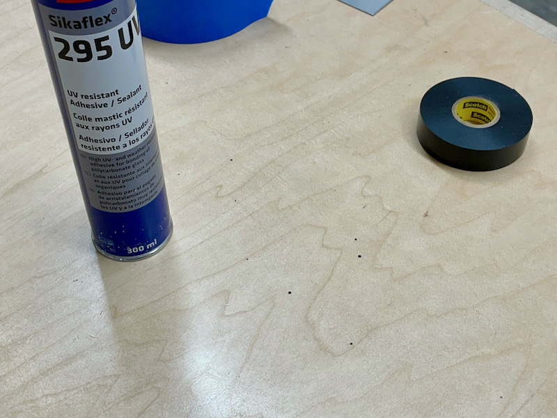
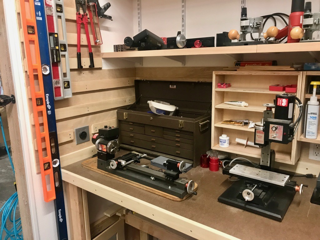
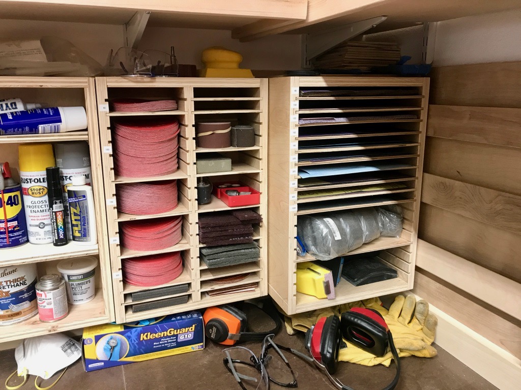
The wall on the this side of the workshop is mostly storage for paint, glue, grease, and other substances. On the right is storage for sandpaper and related items, and on the left is my little machine-tool area.
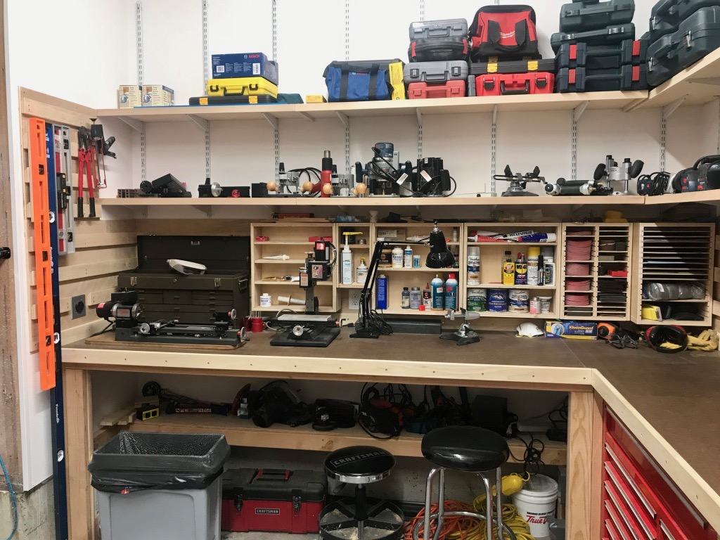
Dedicated space for the little lathe and mill – quite a change from the old house where I had to pack these machines away when I wasn't using them.
I built these simple storage units for sandpaper sheets, sanding discs, etc:
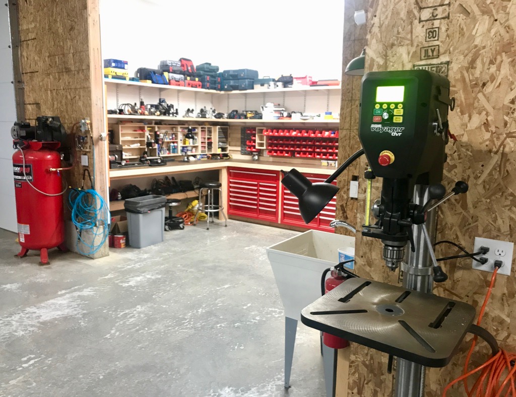
And here are the last two machines, which are also the biggest. The air compressor is the same faithful 60-gallon unit I've had since the beginning. The drill press is a Nova Voyager, which is a very cool new acquisition. It uses a direct-drive motor and can go from 50 RPM to 5000 RPM and back with no belt changes, just a couple of button presses. What a game-changer this thing has been.
As for future workshop projects, the main thing I'd like to do is to insulate and cover the walls of the hangar, because it gets c-o-l-d out there during the long Northwest winter. But as it's currently the warm season, and the workshop is now basically functional and everything has been unpacked at last, I think it's about time to finally get back to airplane-building.
It's funny, though… now that I live in a completely different environment, the mission for what I want to do with an airplane has really changed. In Kansas I used to want to fly as fast as possible to get to the "good stuff", but out here on the west coast the good stuff is all around me. Now what I really find the most interesting is the one thing you can't do in an RV… looking down! Maybe the RV-15 will be a high-wing? Oh well, I have to finish this airplane first, one way or another.

And if you are still reading after all that, some housekeeping: All the images in this and future posts should now be clickable, so keep that in mind if you want to see something in more detail on your screen.