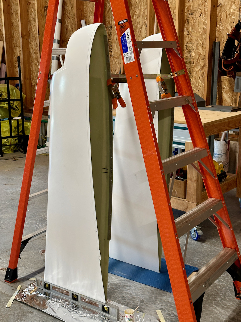
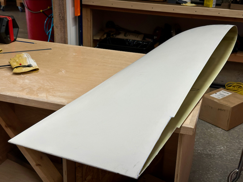
The fiberglass wingtips are large and flimsy, so I've tried to be diligent about storing them in this orientation for all these years. I'd hoped that would keep them from collapsing or becoming distorted – it seems to have worked out, as they're not obviously warped:
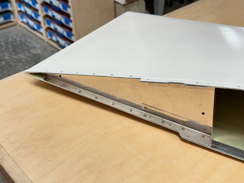
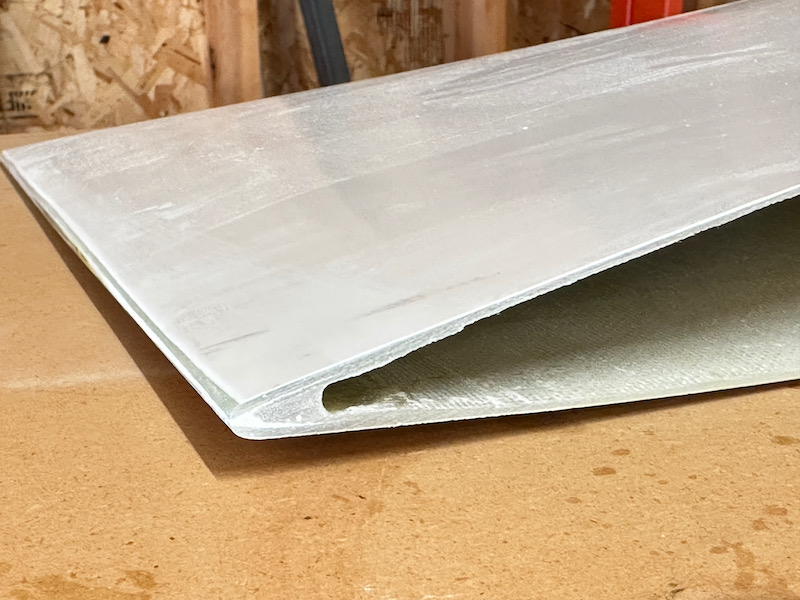
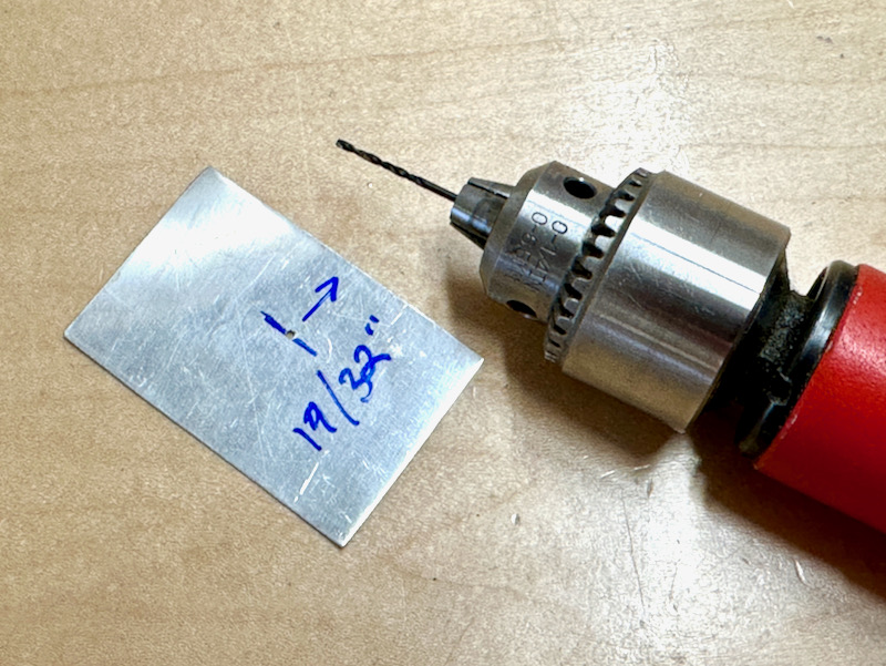
The molded fiberglass flanges are slightly oversize and the edge is uneven, so you have to do some trimming. I measured the depth of the skin overhang on the wings (about 5/8", or 20/32") and then made a little marking gauge so I could draw a line 19/32" from the joggle with a sharpie:
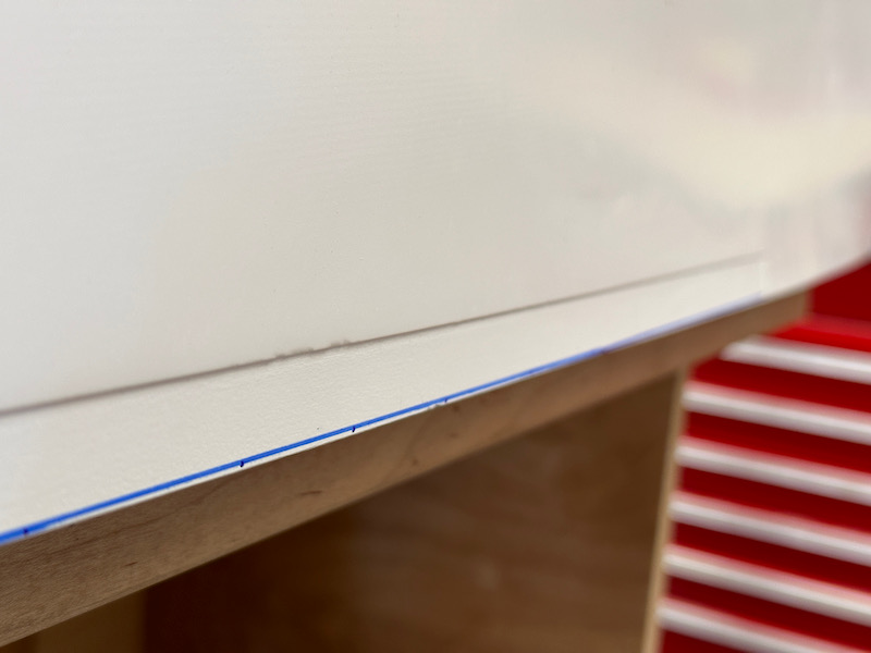
This worked out pretty well, and I found I didn't even need to remove very much flange material:
A sweaty session with the Perma-Grit sanding block was enough to trim and straighten the edges, and then it was a process of iteratively trimming off bits of fiberglass until I could get the wingtips to sit correctly on the wings:
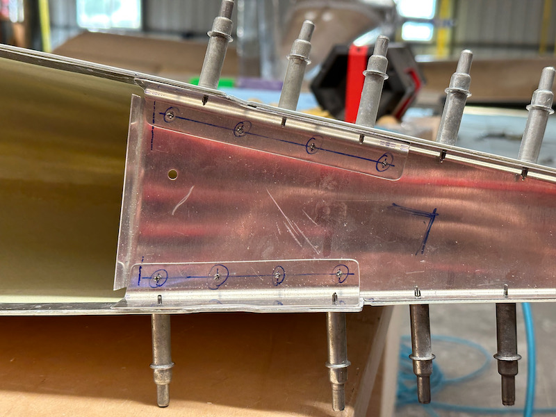
Once I was able to hold the wingtip up to the wing, I marked the approximate location of the fastener holes on the outside of the fiberglass:
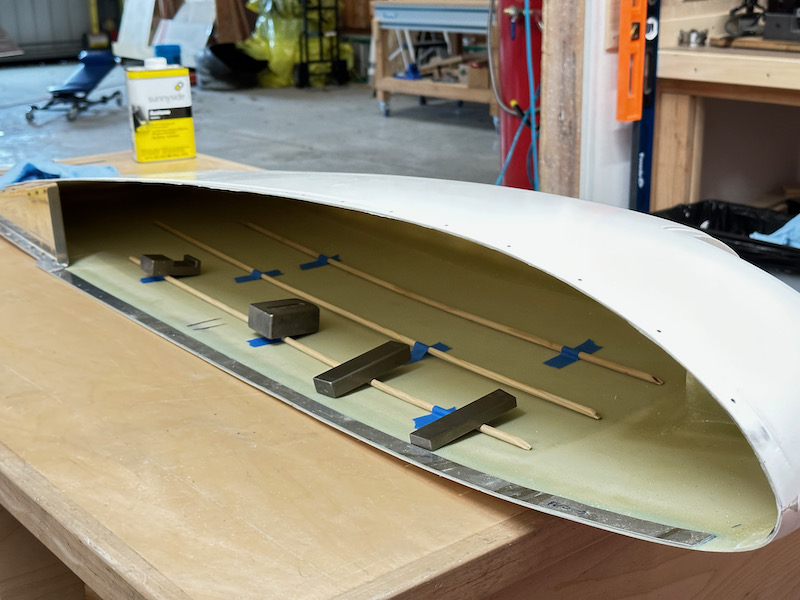
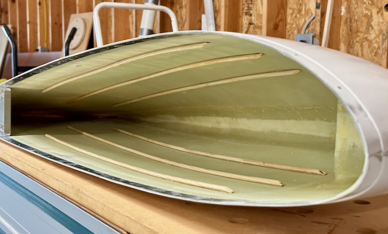
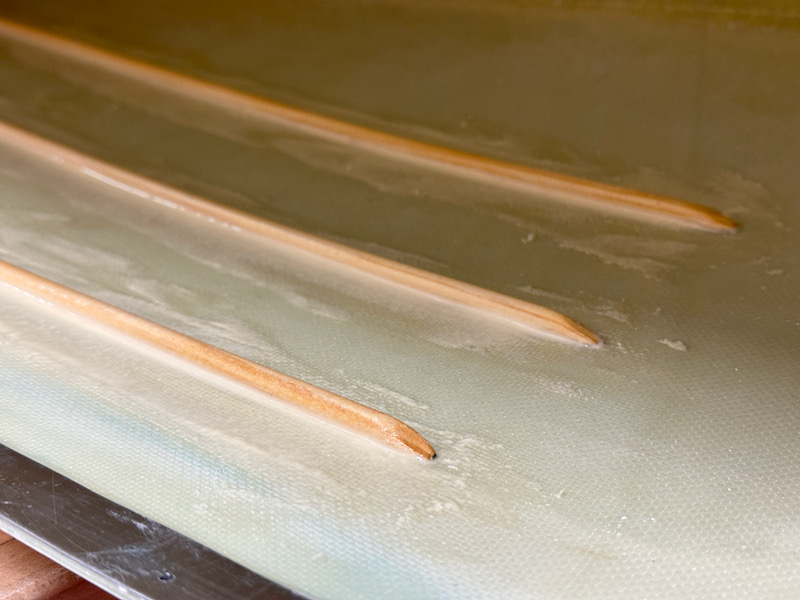
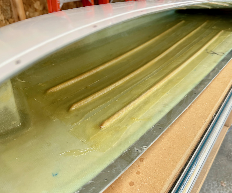
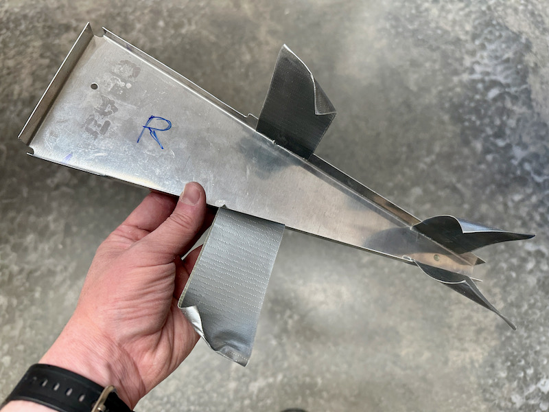
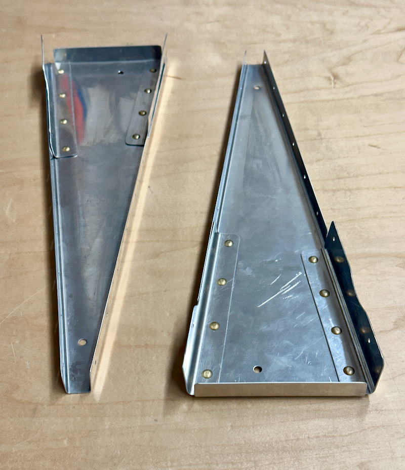
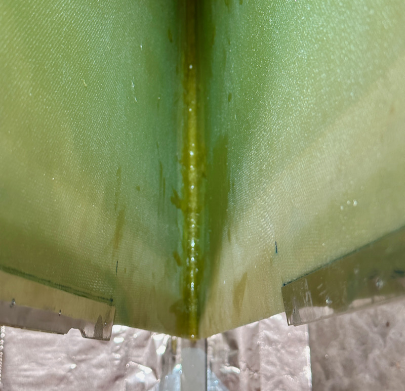
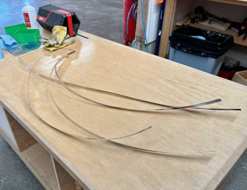
I couldn't find the W-728 reinforcement strips that come with the kit – misplaced in a move, probably – but since I happened to have a four-foot section of 0.020" handy I was able to just cut my own using tin snips. They ended up somewhat curlicued, but that doesn't matter.
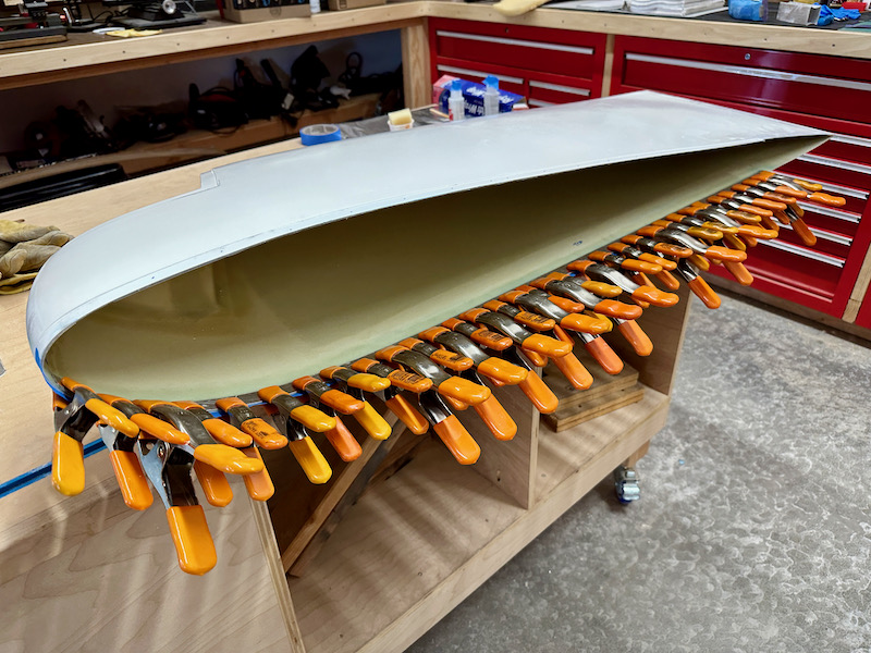
After scuffing and cleaning the mating surfaces, I glued the reinforcement strips to the inside of the wingtip flanges using five-minute epoxy. I used every pony clamp I own to secure each strip as I glued it:
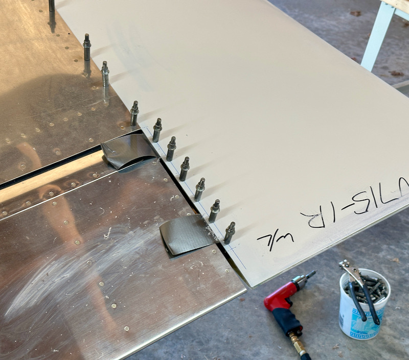
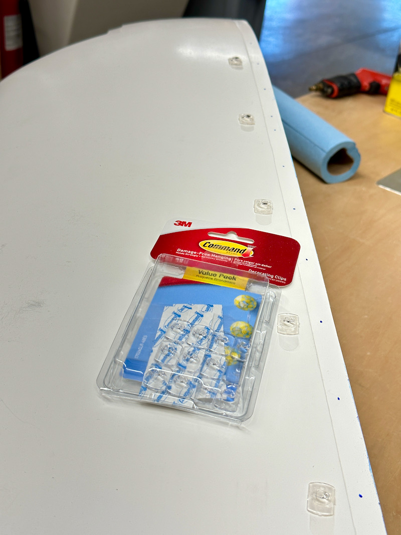
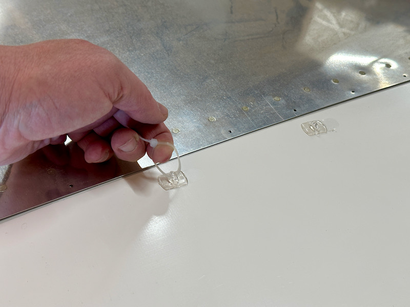
So far I've been following the plans and a helpful how-to article, but here I decided to innovate a bit. I wanted to find a way to pull the fiberglass up to be flush with the wing skin, to make it easier to drill holes accurately and get a good fit. One way to do this is to insert a temporary foam rib inside the tip, or even fill it with party balloons, but it occurred to me that these 3M Command clips might be a viable alternative. We have these things all over our house, and my reasoning was that if they don't pull the paint off my drywall they probably won't pull the gelcoat off my fiberglass either. So after doing some testing on a cut-off piece with favorable results, I proceeded to stick a clip next to every second fastener hole:
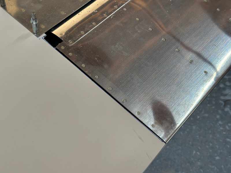
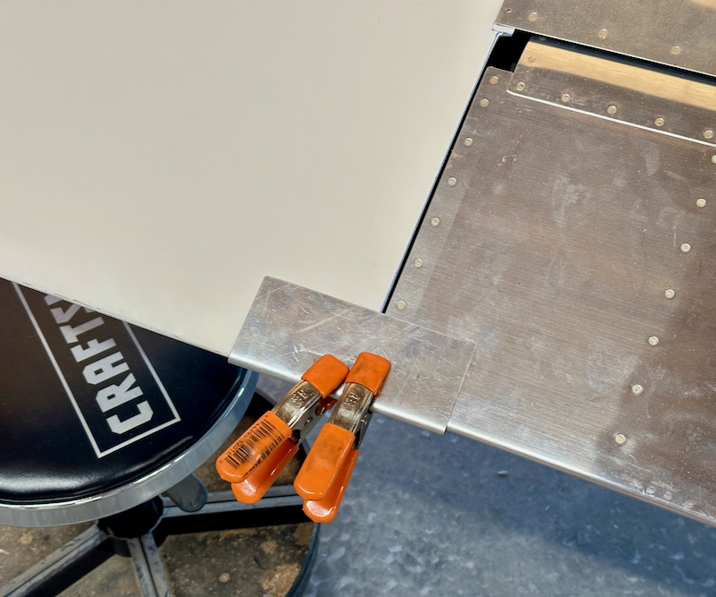
With the wingtip held in place, I used some clamps and a folded piece of scrap aluminum to lock the trailing edges of the wingtip and aileron together:
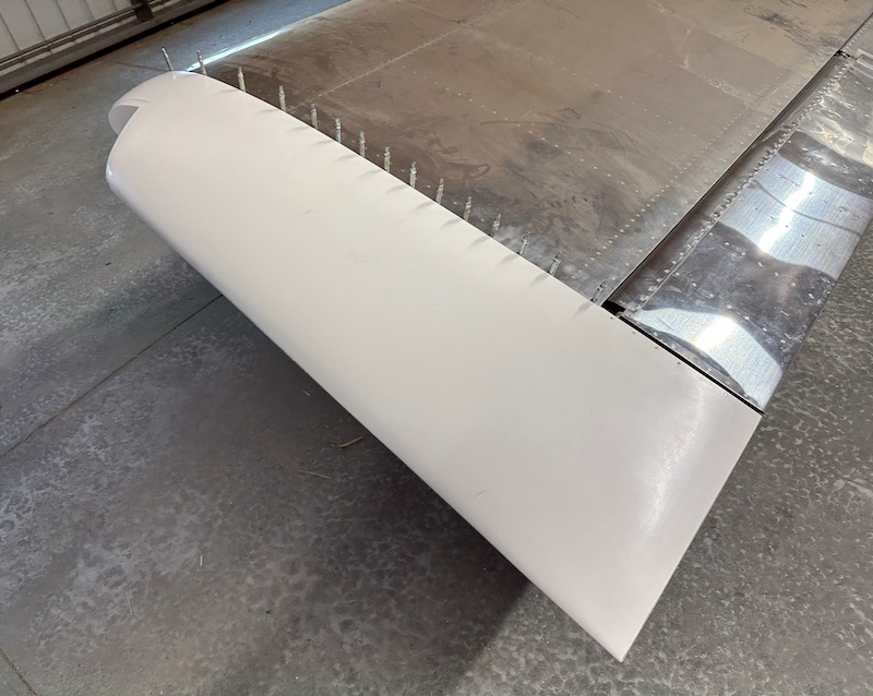
Then after double-checking the alignment of everything, I drilled and clecoed the first hole, starting at the leading edge:
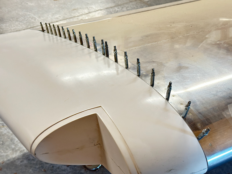
Now here's where the stick-on tabs come into play. Working from front to back, and alternating from top to bottom, I drilled and clecoed every fourth hole, using the adjacent tab to pull the fiberglass flush with the wing skin. A looped zip tie made this easy – I wouldn't suggest using pliers here, as you only want to apply about a pound of force while you carefully drill through:
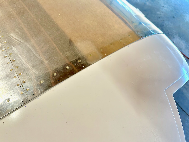
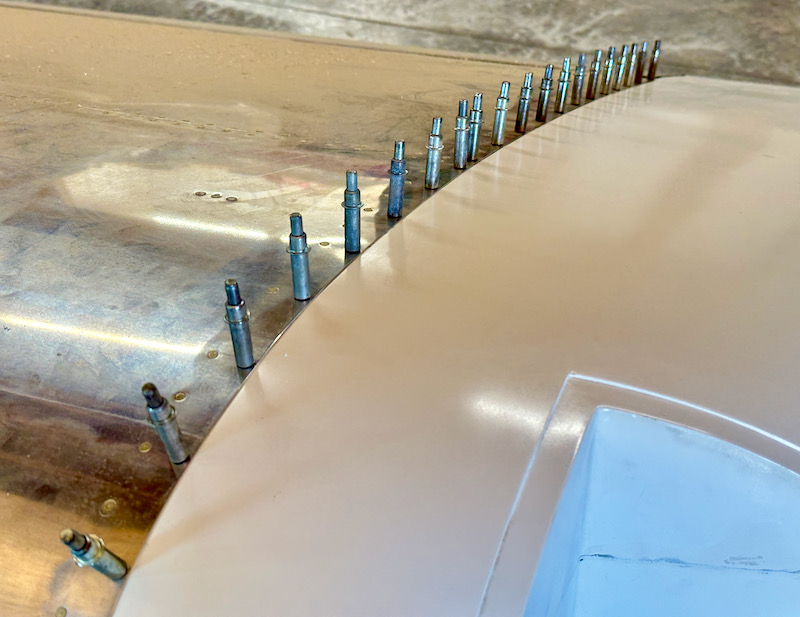
After drilling all the holes that were next to a pull-tab, I was happy to see that the fit was turning out really nice:
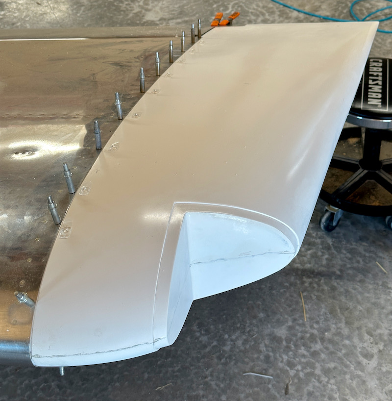
From there it was a simple matter to drill and cleco the remaining holes, and then remove the sticky tabs. Almost all of them came off easily – a few stubborn ones I carefully dislodged with a plastic scraper – and the gelcoat was completely undamaged:
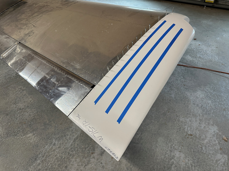
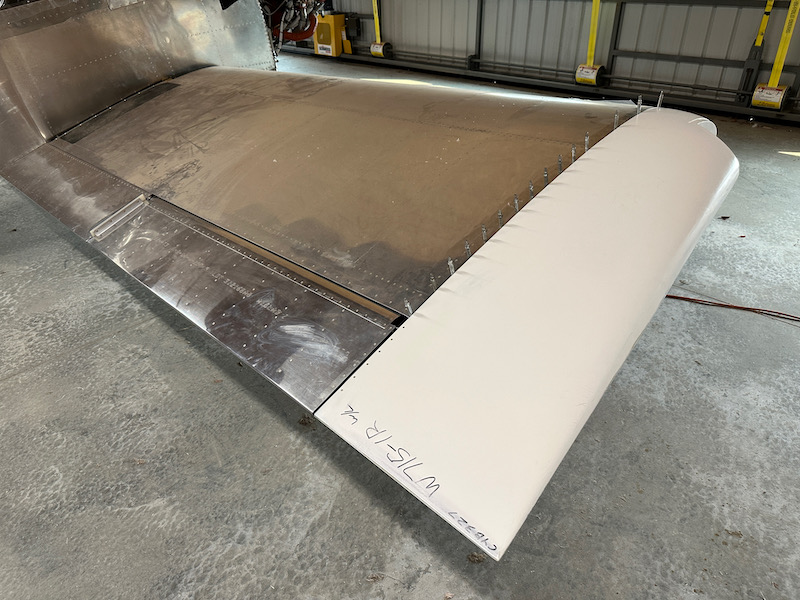
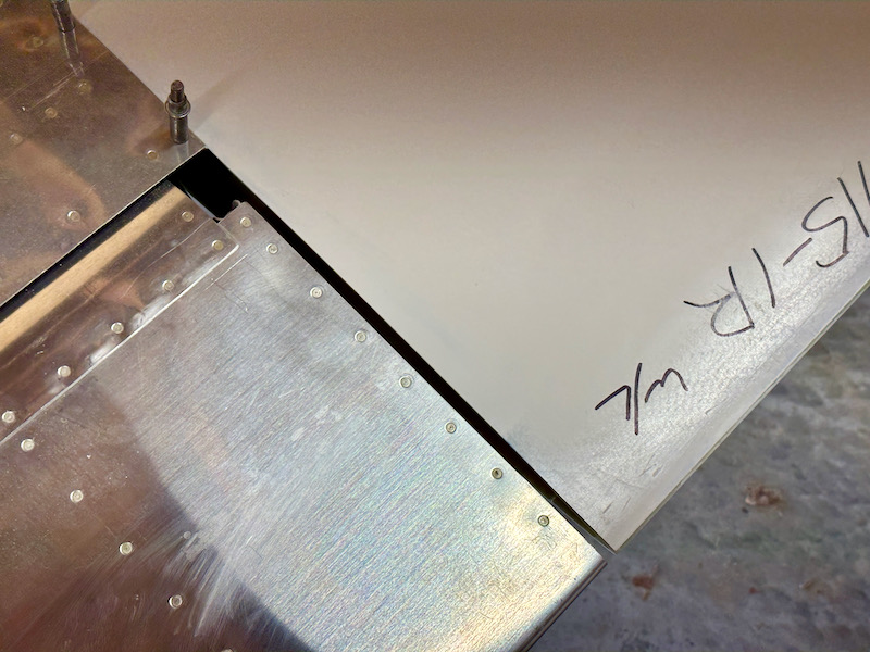
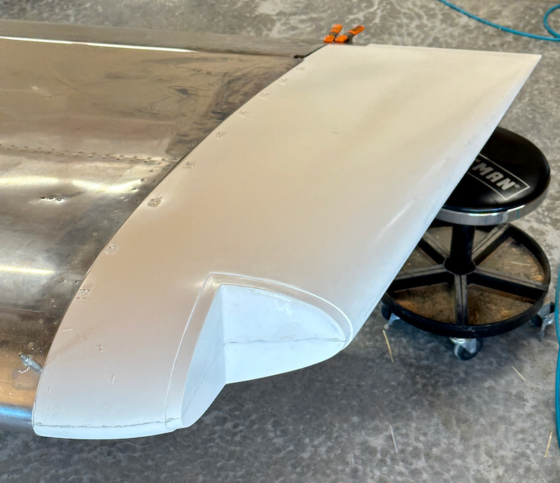
I repeated the process for the other wingtip, with similar great results. I'm very happy with this initial fit:
I still need to trim the trailing edges flush with the ailerons, and clean up the gaps between wingtip and control surface, but the all-important alignment is good on both wings:
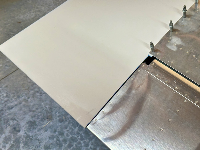
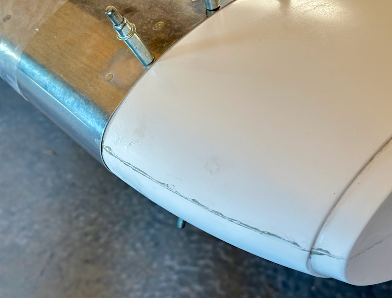
Up front, I will have a little cosmetic work to make the profiles of the leading edges match up:
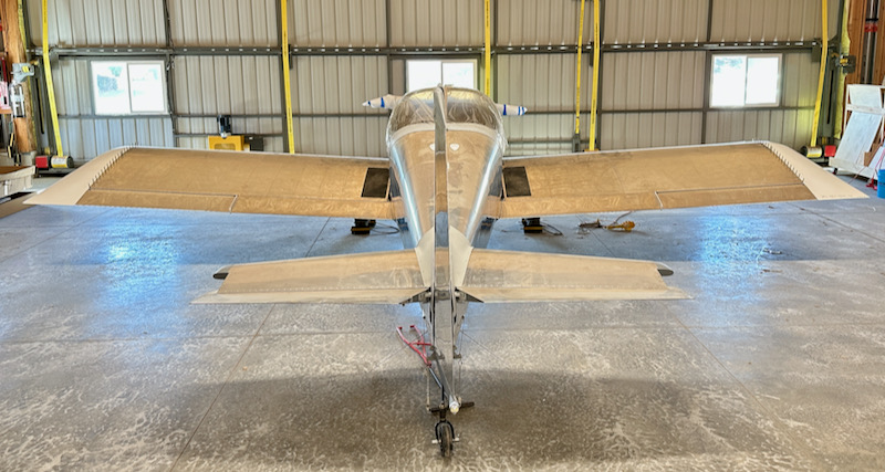
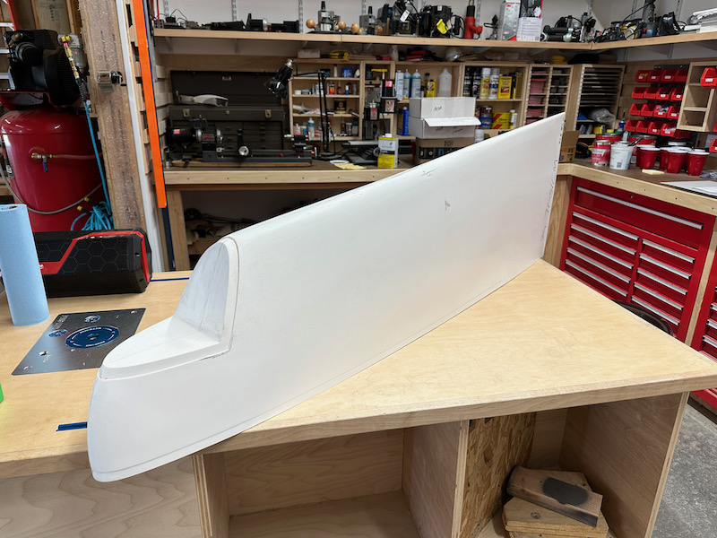
And of course there is a bunch of other work ahead before the wingtips are truly finished, but for now here's a beauty shot showing the plane with its full wingspan achieved at last:
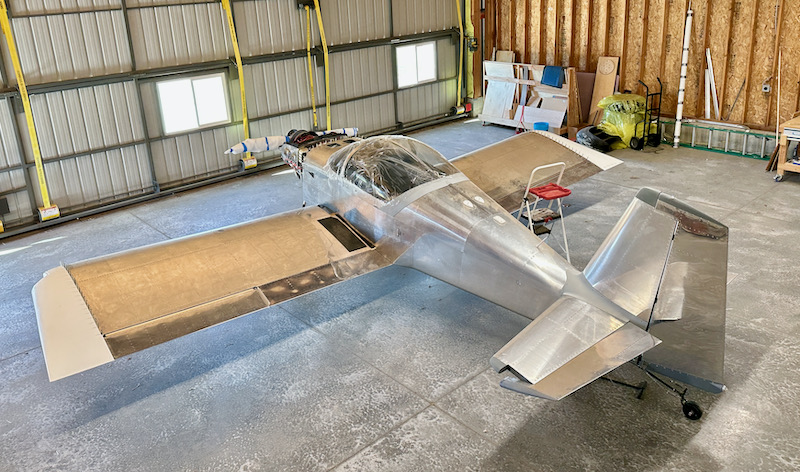
And since it's suddenly three feet wider than it was last week, I'm going to have to be careful not to walk into it: