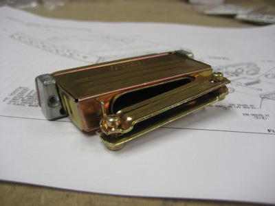
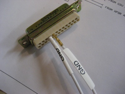
Today I started wiring the radio stack. For starters, here's a reference photo of how the pieces of the D-sub connector backshells for the GNS 430 and GTX 330 fit together; it took me a little while to figure it out from the drawing. And at the risk of biting the hand that feeds, I sure do wish Garmin would have used the same two-piece backshells here that they include with their audio panel. These one-piece jobs make you pass each wire through the backshell before you plug it into the connector, which means the backshell is floating around on the wiring harness the whole time you're trying to build it. It's a pain.
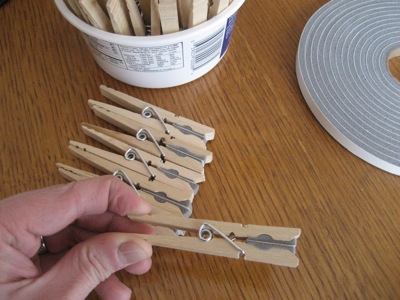
I found myself wishing for an easy way to temporarily pin together a bundle of wires, and in a rare burst of insight I realized that an ordinary clothespin with some self-adhesive weatherstrip on the jaws makes a pretty good little cushioned clamp. Total cost: zero dollars, since I had all the materials laying around the house.
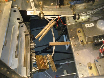
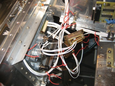
I used the clothespin-clamps today when I was initially stringing wire bundles, then came back later and replaced them with still-temporary-but-not-quite-so-much twist ties. In this photo I'm starting on the wiring for the transponder:
Each radio has numerous power and ground pins, and in most cases you can run multiple wires into a single PIDG terminal on the other end. Here I've combined four 22AWG ground wires for one of the 430s into a single blue (14-16AWG) terminal.
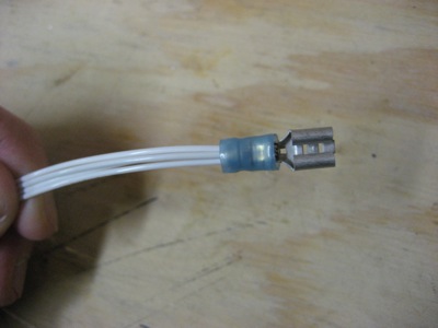
The comm power input on the 430 runs off a 10-amp breaker and takes a doubled-up pair of 18-gauge power and ground wires… wow, that's a lot of current! Since 18AWG wire is way too big to insert in a standard D-sub pin, the 430 install kit includes a small handful of these special crimp sockets with heavy-gauge barrels. Since they stick out from the connector, you have to insulate them – no big deal for me, since I'm using my label printer to make labelled heat-shrink tubes for every one of these wires anyway. By the way, I crimped these suckers with my Daniels crimper – no positioner necessary, I just eyeballed it.
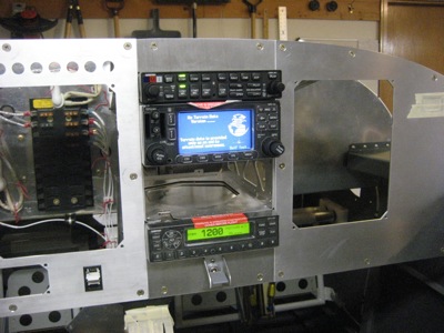
Following an afternoon of wiring, I now have the power and ground wires run for the audio panel, transponder, and one of the 430s. There is still a lot of wiring to be done for audio, data, and antenna wires, but this is enough to turn on three of the boxes. In the photo below you can see that I've left myself generous service loops in case I ever need to work on these connections later on down the road. I also have not bolted the connectors to the radio trays, since I don't want to have to worry about potentially bending one of the pins if I don't have to.
Apply power, and… it's alive! Of course I tested each component individually first, but this is the coolest picture.
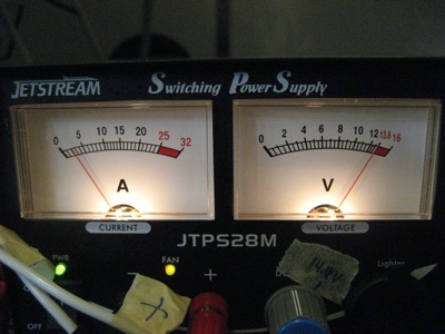
According to the meter on my bench power supply, these three boxes running – without transmitting or doing anything strenuous – draw about three amps. That's a bit less than what I had in my power budget.
I would have wired the other 430 as well, but I ran out of both 18 and 22 gauge wire. Initially I thought that the 100-foot spools I bought would be more than enough, but now I see that there is way more wire in this project than I would have guessed. I bet I'll go through a quarter-mile of wire before all is said and done. Time for another visit from the UPS man…