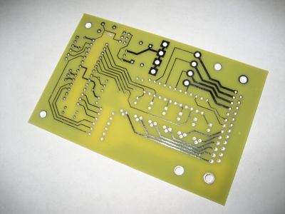
I got my annunciator controller board back from ExpressPCB. Their board layout software is pretty terrible, but the finished product looks okay. If you look closely, you might be able to spot the switch mounting pad I had to grind off because it was too close to the processor reset line. A real board layout tool would have caught that with a design rule check, but of course the crappy free software doesn't have one. Oh well – that turned out to be the only mistake I made (and believe me, nobody is more surprised than I am).
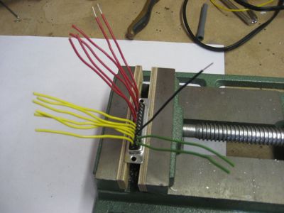
I grabbed a spare D-sub connector and made a little test harness to power the board and test its inputs and outputs.
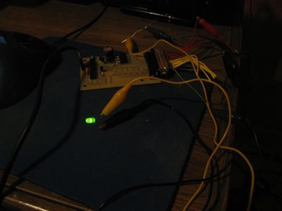
In keeping with the time-honored traditions of testing out a new PCB design, I soldered the minimal components needed to get the processor running (power supply, oscillator, and the microcontroller itself) and hooked it up to the debugger to see if I could make it blink an LED.
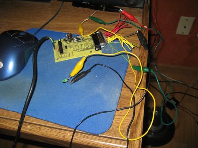
It blinks! This means that the microcontroller is alive and can be programmed. It doesn't look like much, but if a board can get to this stage, then almost everything is working.
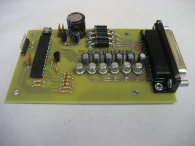
Here's the finished product, with voltage dividers, filters, and driver transistors in place. It will be able to sense up to 8 inputs and control up to 6 annunciator lights, depending on how I choose to write the finished firmware. The end goal here is to be able to do a few things with warning lights that are just slightly more sophisticated than simply hooking up a lamp.