The wiring instructions for the Lightspeed ignition system are full of unusual requirements without explaining the reasons behind them. I decided to deviate from the suggested schematic in a few specific ways. Disclaimer: think carefully about how you wire your ignition system, and be careful when deviating from the manufacturer's recommendations.
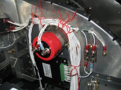
To provide the ignition with a redundant source of power from my aux battery, I used a pair of Schottky diodes in a handy two-in-one package. Of course, the reason for using a Schottky here is to minimize the forward voltage drop. Power Schottkys are kind of hard to find in a convenient package – i.e. with mounting holes, insulated base, and non-solder terminals – but I got a tip about IXYS products and found this diode that is more than adequate for what I need.
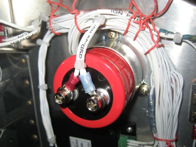
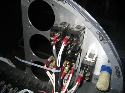
The big red thing is a noise filter capacitor I installed to try and preemptively deal with the reported power supply ripple that the ignition has supposedly been known to generate. This is the same 26,000 uFd cap they install with MSD race-car ignitions, so hopefully it will do the trick. It's certainly big enough. It fits pretty well on the passenger-side subpanel, which is just a few inches aft of where the ignition will go.
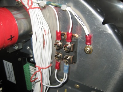
The Lightspeed instructions tell you to use shielded wire for all the power connections, with the shield used as the ground return. This is impractical with my setup, although I did use shielded wire for the connections from the batteries to the diodes (with the shields used in the normal fashion, and grounded to a handy screw on the subpanel). A short length of wire connects all the ignition stuff to the single-point ground block on the firewall, and I deemed the wiring from the diodes to the capacitor to the ignition to be short enough as to not require me to fool around with shielding. Hopefully all this will be enough to avoid having ignition noise in my headphones.
Last wiring task of the day was to run a length of shielded wire from the ignition over to the corresponding switch on the pilot's side of the panel. The ignition always has power, even when the airplane is off, but it has a separate "enable" input that's wired just like a magneto P-lead. Closing the switch grounds the faux P-lead to its shield, disabling the ignition. I chose to use this approach rather than switching the power input (which you can also do) because the relative locations of all the various components would require that approach to use a whole lot more wire (and current-carrying, noise-radiating wire at that).
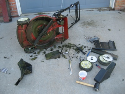
I would have spent more time working on the airplane this weekend, but I had to spend a whole afternoon fixing the mower. Grrr.