I'm using Amploc brand Hall effect sensors (most easily found as a GRT accessory) instead of shunts to measure alternator current in my airplane. You pass the bus wire through the middle of the sensor, which is a bit less than an inch in diameter:
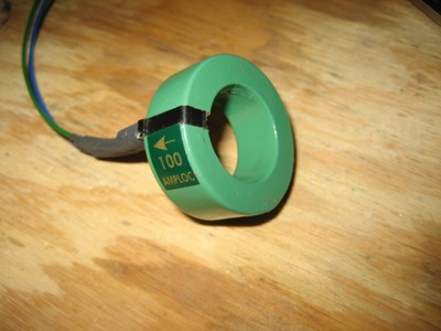
The wire doesn't have to be centered inside the sensor, but I still wanted to come up with a way to secure it and make it look nicer. This just looks sloppy to me:
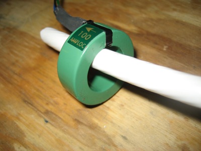
I went up to Airparts and bought some 1" diameter nylon rod, then turned it down on my lathe so it would exactly fit the inside diameter of the current sensors. Having a lathe is great, even if I am only barely competent at using it.
![]()
With a bit chucked in the tailstock, I center-drilled the nylon to fit the diameter of the wire. After I took this photo, I parted off what I needed and cleaned up the ends a bit.
![]()
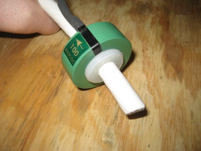
Voila, now it's a perfect fit:
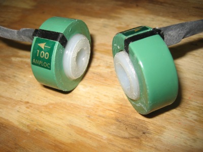
I made one spacer with a 3/8" hole to fit the #4 wire from the main alternator, and another one with a 5/16" hole to fit three turns of #10 wire for the secondary alternator. With a Hall effect sensor, running multiple turns of wire through the sensor gives you a current reading that's multiplied by the number of turns, which your engine monitor then divides back down to give you the true current value. This is a handy way to increase the accuracy of the measurement, as long as your EFIS supports it, which mine does. Since these are 100A sensors, three turns of wire from the 20+ amp standby alternator should be just about right.
I glued the spacers into the sensors with E6000. Nylon is resistant to most glues, but I'm hoping this stuff will grab hold of the roughed-up surface.
Next: Off to Oshkosh for a week…