Since air-cooled airplane engines don't have a ready supply of hot water to run a heater core, the only way they can provide warm air in the wintertime is by taking it from the outside of the hot exhaust pipes. This involves the use of a cylindrical heat exchanger, also called a heat muff, placed around one of the pipes and connected to inlet and outlet tubes, which are usually SCAT hose.
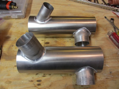
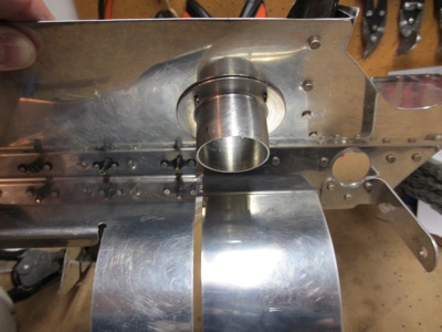
One of the little gotchas about the IO-360-M1B engine I have (parallel valve, horizontal induction) is that the only good place to position a heat muff is on the #1 cylinder, which happens to be the one farthest from the firewall and thus requires a long and convoluted hose run. Such is life. The other fun thing is that the heat muff that came with the firewall forward kit didn't fit at all, so I had Rick Robbins weld me up a new custom one. Here's the old one in the foreground, with the new one behind. The new heat muff has the inlet pointing the other direction; the inlet is also downsized from 2" to 1.5" in an effort to reduce the airflow velocity and hopefully thus allow greater transfer of heat.
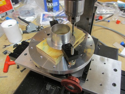
Since there were no mounting holes in the aluminum flange I bought, I used my mill to make some. I swear, I get more use out of my rotary table than I ever thought possible. It's perfect for little jobs like this.
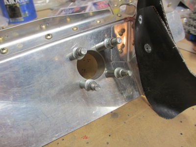
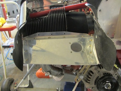
I cut a hole in the #1 cylinder baffle, and match drilled mounting holes for the duct flange:
Another view from below… locating this correctly is trickier than it seems, due to various clearance issues that are hard to photograph but become apparent when you actually have the parts in front of you.
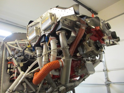
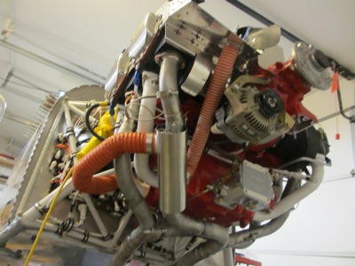
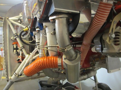
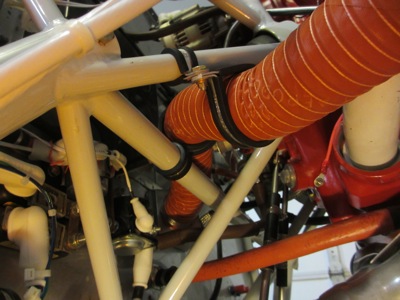
Test fitting the heat muff and trimming the hoses to length. Inlet air comes from the front baffle, goes down into the bottom of the heat muff, flows upward past the hot #1 exhaust pipe, and exits into a long awkward hose run that goes around the #3 pipe and up to the firewall, where the heat valve is located.
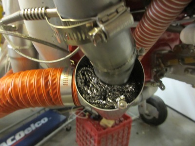
I packed the inside of the heat muff with stainless steel kitchen scrubbing pads, with the intent of further slowing down the incoming air and giving it more surface area from which to transfer heat. I heard about this trick from VAF, and it seems like it could be a good idea for increasing the heater output. Shouldn't hurt, anyway.
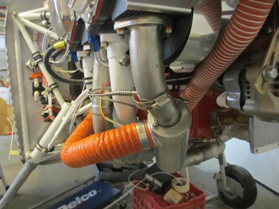
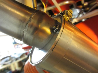
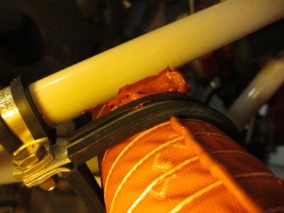
The amount of clearance between the hose and the #3 exhaust pipe is adequate, if not ample:
Except, oops, there's nothing to stop the heat muff from rotating around the exhaust pipe, which could allow it to twist as shown here and put the hose in contact with the hot exhaust pipe. Not to mention, allowing the heat muff to spin back and forth will probably eventually saw a hole in the exhaust pipe. Not so good.
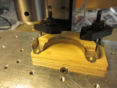
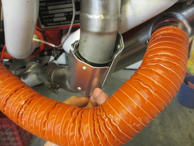
I solved this problem by modifying the heat muff design a bit. Each end cap is assembled from two stainless steel half-moon shapes, and then the opposite end caps are tied together with tension rods. I wanted to allow the two parts of each end cap to cinch down tighter on the pipe when the end clamps are tightened, so I used the mill to elongate the holes into slots.
Now the heat muff fits much tighter around the pipe when the band clamps are tightened. It's still not completely fixed in place, but it now takes much more force to rotate it. Seems good enough.
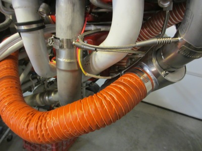
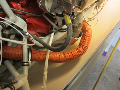
I used a series of adel clamps to secure the 2" SCAT hose where it passes through a jungle gym of engine mount tubes:
Another view from below. The clamps keep the hose from rubbing on the engine mount, and also help aim the hose through its arc around the #3 cylinder.
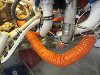
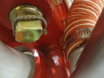
I installed a couple of radiant heat shields on the #3 pipe where it's closest to the SCAT hose. Another thing that I figure can't hurt:
I laid a bead of RTV along the length of the SCAT hose, which is supposedly an old mechanic's trick intended to keep the hose from totally coming apart if the string starts to unravel.
More RTV:
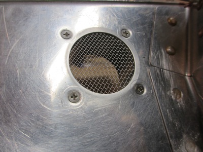
To keep bugs and other critters out of the heat system, I installed a piece of window screen between the baffle and the duct flange:
Close up of the inlet screen:
The included instructions didn't explicitly say to safety-wire the band clamps that keep the heat muff together, but it seemed sensible and was easy to do:
I squirted a bead of RTV into the gap between the inlet hose and the oil sump, since the clearance is pretty tight there:
And some more RTV between the hot air hose and the engine mount, just in case the clamps want to shift. I think I've gone through three tubes of RTV just in the last few weeks.
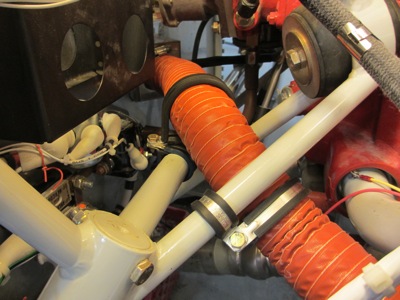
With the lower cowl installed, there's about an inch and a half of clearance between the SCAT hose and the cowl. That should be just enough. I don't know how the stock heat muff would have ever fit, since it has the hot air outlet at the bottom.
I think the heat system is complete now. Just in time for summer to get underway!