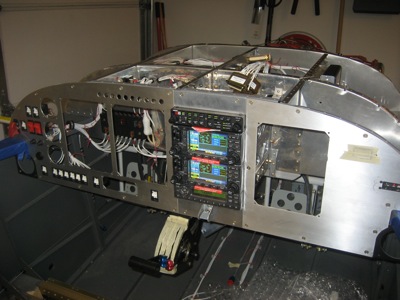
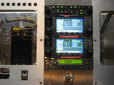
I ran the power and ground wires to the second 430, which let me get this awesome photo of the whole radio stack lit up:
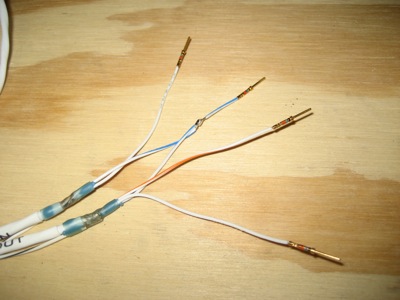
I started running wires between the radios and the audio panel using the shield termination techniques describer earlier. Strangely, the GNS 430 has separate "low" pins for the microphone input and comm audio output, but the GMA 347 audio panel only has a single "low" pin per radio. That means you have to splice them together at the audio panel end – you can see in this photo how I soldered one to the other. The joint got covered by heatshrink later on.
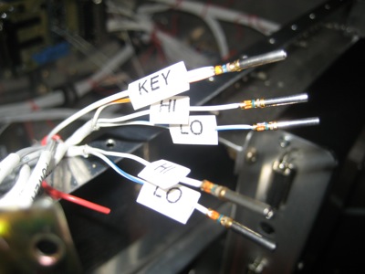
At the radio end, the mic key input pin on radio #1 is wired to the transmit interlock pin on radio #2, and vice versa. This tells the non-transmitting radio to reduce its receiver sensitivity when the other radio is transmitting, preventing its input from being overloaded and breaking squelch. If you look closely you can see the tx interlock wire leading off from the PTT pin.
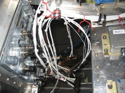
I ran the wires from the comm and nav audio outputs on both radios to the audio panel, and from the audio panel to the radios' mic audio inputs. All that shielded wire is starting to make for a pretty hefty wire bundle. I'll terminate the shield wires later on.
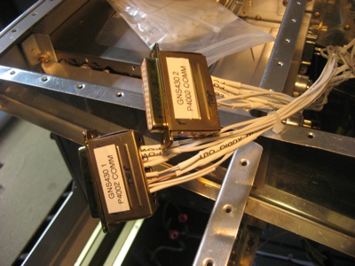
The comm connectors on both radios are now fully hooked up. I need to put on the strain relief clamp thingies still. Once again, I am being a fanatic about labeling stuff – the better to make my life easier when doing future maintenance.
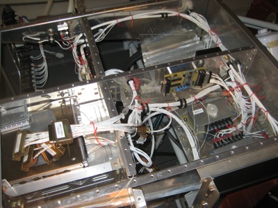
I've started replacing the temporary wire ties in the radio wiring harness with actual tie wraps, so I can keep things neat and tidy.
Wires, wires everywhere. I think I'm doing an okay job of keeping it all organized, though.
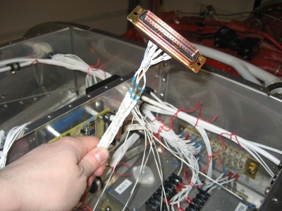
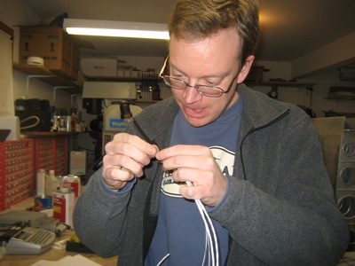
These tiny connector pins are very fiddly. Thanks to Mary for the documentary photography.
I know I already showed you a picture of the radio stack powered up, but I really like this one too. So you get to see another one.