My old rudder didn't make the cross-country move to our new house, partly due to damage during packing (my fault) and partly because I was still unhappy with the trailing edge (also my fault). So, finding myself with an RV-7 lacking a rudder, I needed to build another one. But this time, instead of building another RV-7 rudder – which is actually an RV-9 rudder – I decided to build an RV-14 rudder. Confused yet?
The original RV-7 rudder design was similar to the RV-8, with a folded trailing edge just like the elevators. Then later – for aerodynamic reasons that were, depending on who you ask, maybe necessary and maybe not – the kit was changed to use the same rudder as the RV-9. That rudder (i.e. the one I originally built) was bigger, had thinner skins, and a different method of construction involving the dreaded trailing edge wedge. Then much later the RV-14 was introduced, which presumably had yet another new rudder design, or so I thought. However, one day while perusing the RV-14 plans, I saw that a lot of the part numbers were similar or identical to the RV-7/9 rudder, plus some internal structural changes that would seem to make the RV-14 rudder a stronger and better design. So I decided to order the parts to build an RV-14 rudder and see if my hypothesis that it would fit on an RV-7 was correct.
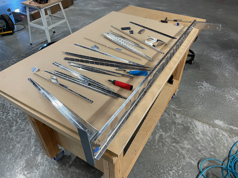
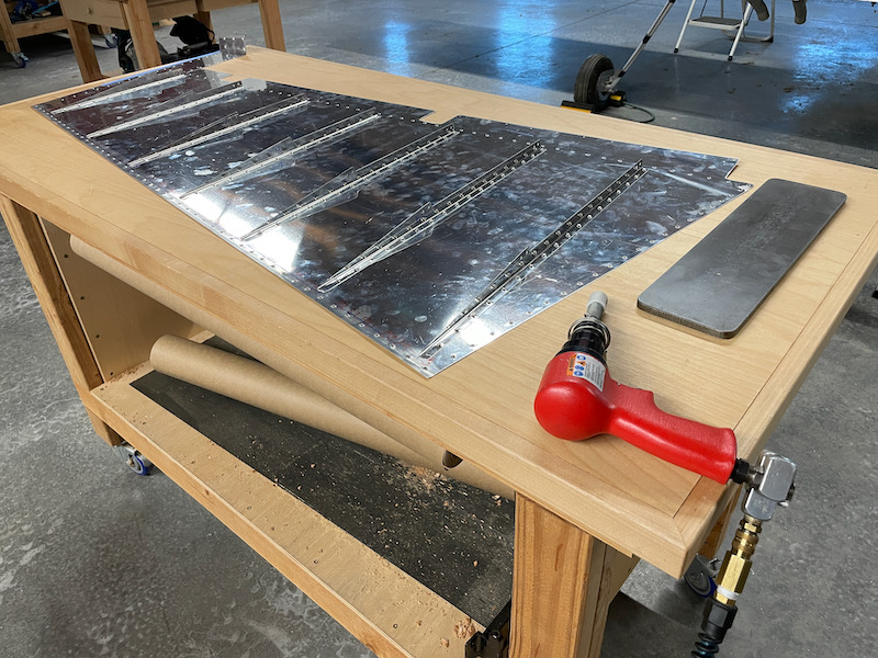
First things first… I've been working on Systems tasks for so long that I almost forgot how much of your time building the sheet metal parts is spent on deburring!
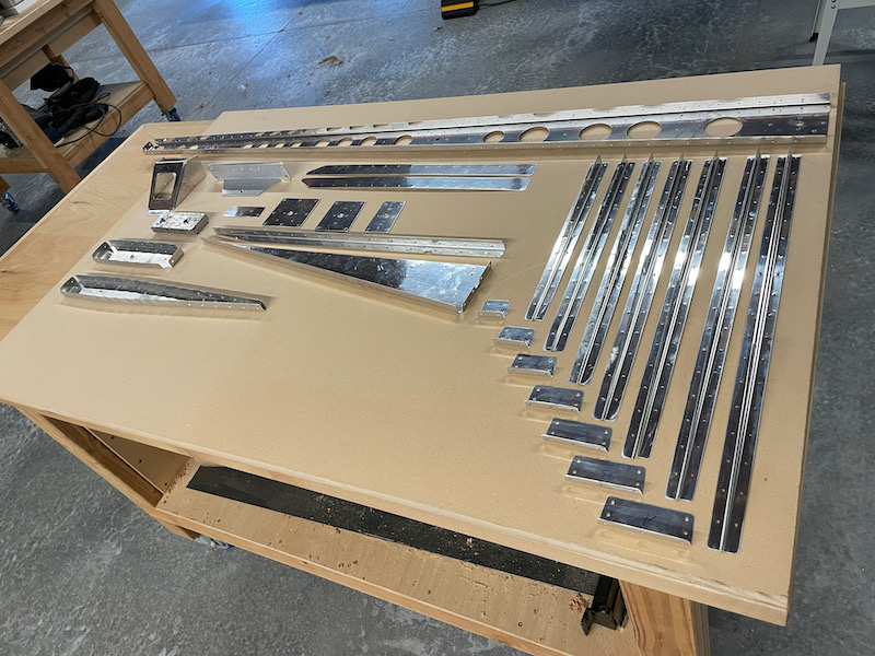
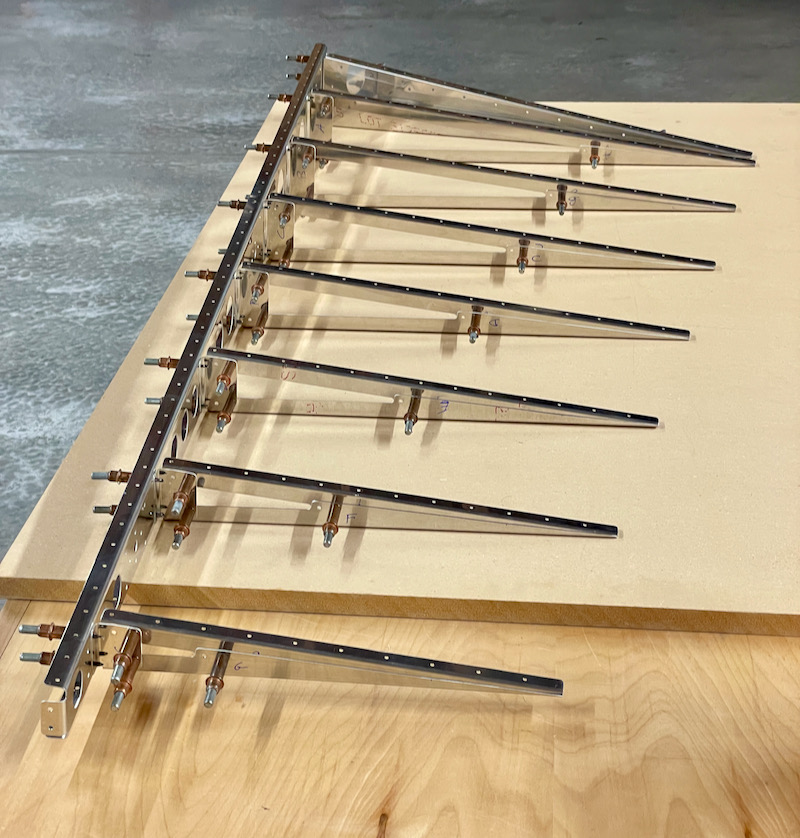
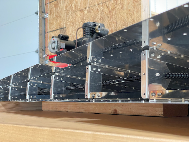
Unlike the RV-7/9 rudder, whose skin stiffeners are simply left floating and not connected to anything, this rudder has a proper internal structure – essentially a set of built-up ribs:
I cut the proper angle (about 5° if I recall correctly) on a piece of scrap wood, to act as a guide for drilling the trailing edge:
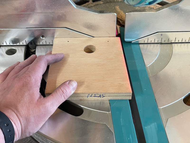
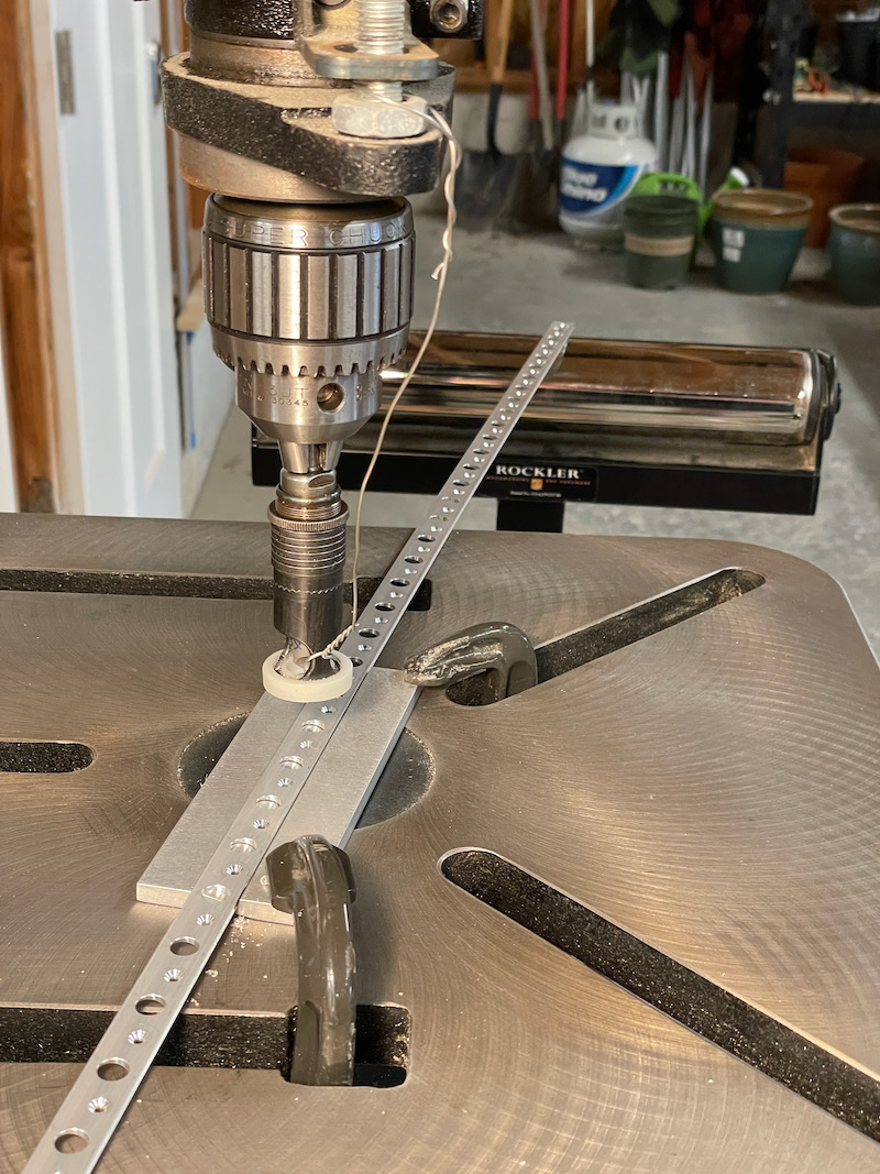
With my table saw, I cut the same angle from the edge of a 2×4, and used it on the drill press to drill a series of angled #40 holes in a piece of hardware-store aluminum angle. The hole pattern has the same 1" spacing as the trailing edge.
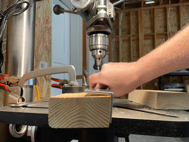
I used the guide block to hold the drill at the correct angle while match-drilling the skins to the trailing edge wedge, and clecoed the trailing edge to the guide angle as I went. The idea is to always use the guide angle to keep the trailing edge perfectly straight until it is riveted:
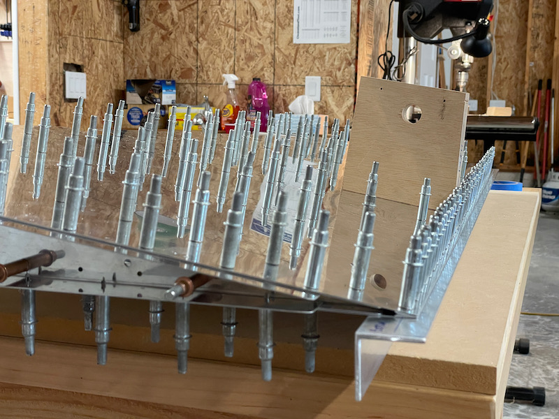
More deburring, and then I riveted together the spar, counterbalance rib, and the collection of parts at the bottom of the rudder:
To countersink the trailing edge wedge I used the Cleaveland jig that's made for this purpose. It worked great – I only wish it was slightly longer, as it was very close to being too short to clamp to my large drill press table. The countersink cage is temporarily safety-wired to the drill press quill to stop it from spinning:
I used an edge-rolling tool to slightly break the edges of the trailing edge, and clecoed everything back together with the guide angle to check the fit. Looking nice and straight so far:
Back-riveting the stiffeners to the skins. You may notice I decided not to apply anything to the inside of the rudder other than fingerprints… I'm trying to get this airplane done and I didn't want to spend time messing around with primer. If it's good enough for Cessna it's good enough for my RV. (actually I did prime one part, the rudder horn which is made of 6061 aluminum)
In the time I've been away from control-surface-building, Van's has switched their recommended trailing edge bonding process from Proseal to VHB tape. Fair enough, should be less to clean up.
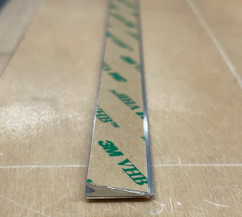
I cleaned and scuffed the mating surfaces, peeled the tape backing from one side of the trailing edge, stuck it to the skin, and left it all clecoed to the guide angle overnight to let it cure fully:
At this point the assembly process diverges from the RV-7/9 rudder – they have you riveting the internal stiffeners and clips together, while progressively bonding the remaining skin to the trailing edge. It pays to have a helper for this step. And yes, there are two rivet holes at the aft end of each pair of stiffeners, but the plans tell you to rivet only one of them.
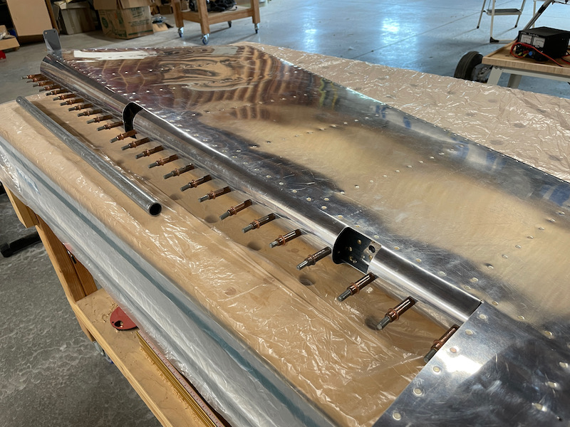
My only modification to the rudder design was to add a 1/4" lighting conduit for the top light. It's held in place with a few lightweight clips I made from scrap aluminum, with blobs of RTV in strategic places to stop it from rubbing.
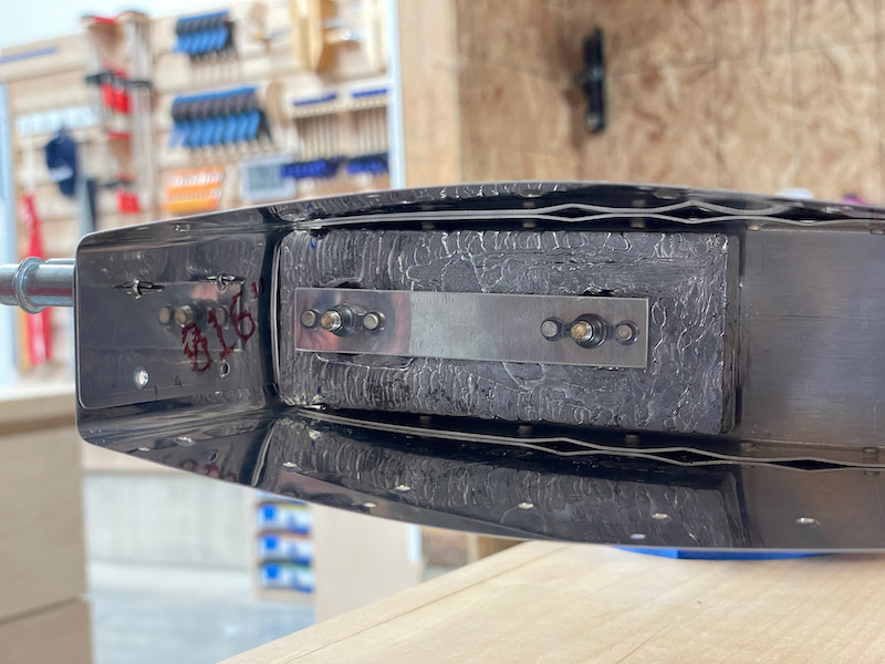
The rudder counterweight is the same design, except they've replaced the inaccessible nuts with a pair of nutplates. This is a good improvement since you can now re-torque the counterweight mounting screws from the outside if you ever need to.
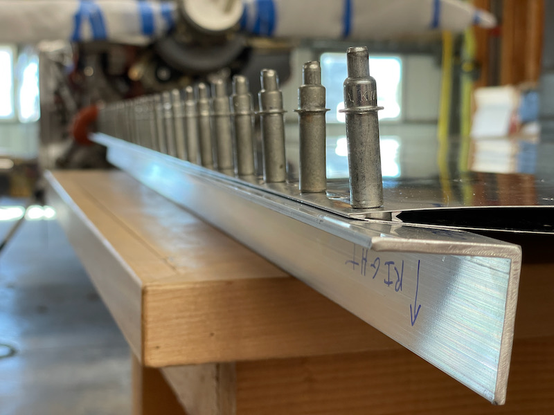
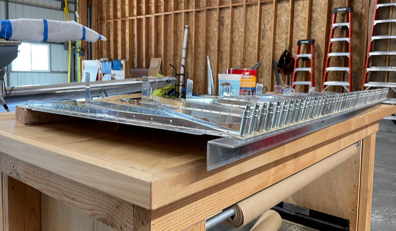
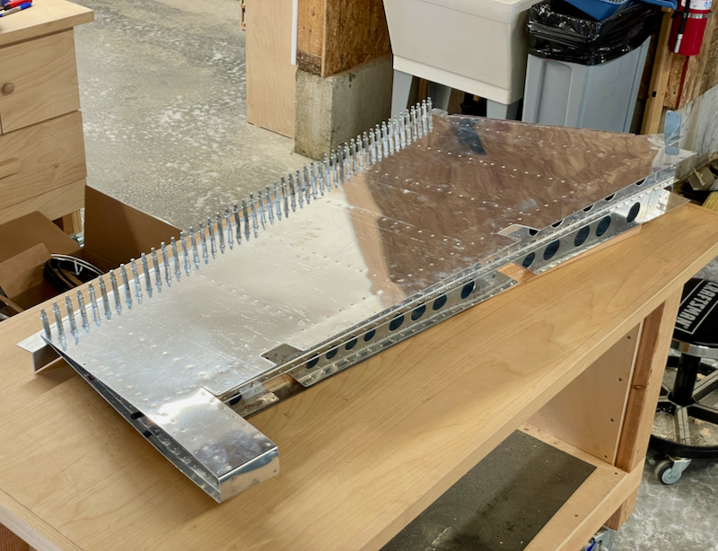
Everything here is riveted except for the leading and trailing edges – time for the hard part:
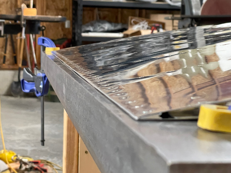
I polished up my steel back riveting angle and used it to partially set all the trailing edge rivets, following the pattern suggested in the plans. So far so good:
This is the point where things started to go less well. I decided I'd use the Cleaveland trailing edge squeezer set I bought to finish setting the rivets… in retrospect I would have gotten better results if I'd just continued back riveting. I have now tried to squeeze trailing edge rivets on two different rudders, and I just cannot seem to get the results I want.
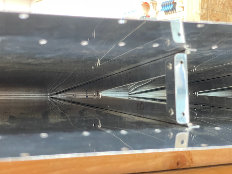
The angle of this photo makes the trailing edge look much worse than it actually is – it really only varies about ± 0.040" over its length, which is less than half the allowed maximum amount. And if you're standing more than two feet away it looks perfectly straight. But darn it, I wanted it to be perfectly straight. If I ever have to do one of these wedge-type trailing edges again, I hereby resolve to leave the squeezer in the toolbox and do it all on the back rivet angle.
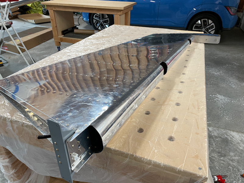
I used the J-hook method and a piece of 1" OD conduit to roll the leading edges together. Happily, the required spacing for the hooks matched the hole pattern on my woodworking assembly table, so I didn't even have to come up with a way to mount the hooks. I used Gorilla tape to attach the pipe to the skin and just cranked away. Once the hooks started getting in the way, I removed them and finished the bends by hand and by eye.
In retrospect it might have been better to use 1 1/4" OD pipe for the middle and lower sections, as the 1" diameter pipe seemed to produce a bend that was slightly too sharp. But I still got the skins to fit together with just a little finger pressure:
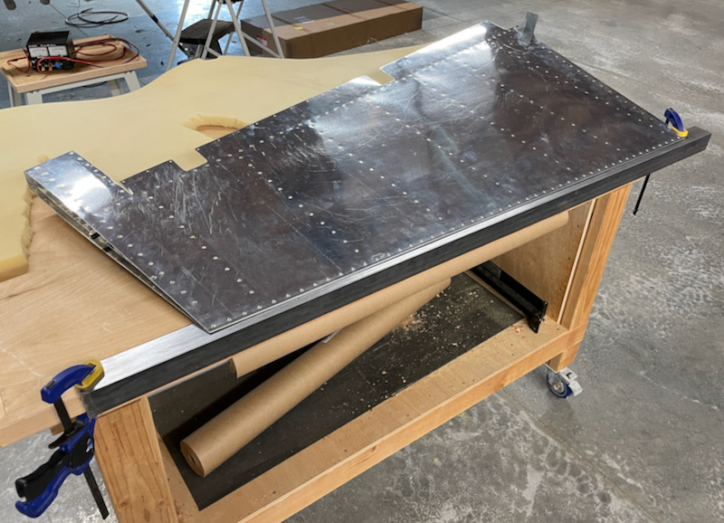
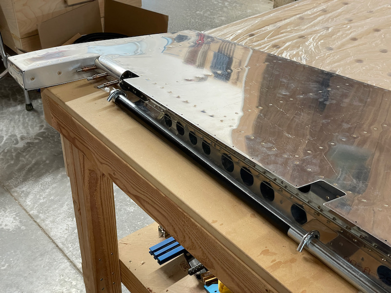
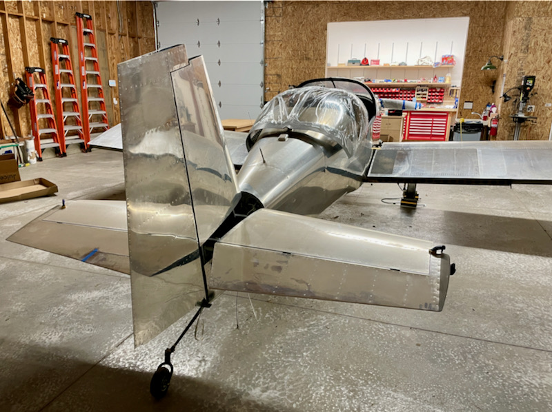
Pop rivets in the leading edge, and now the RV-14 rudder is done. Nothing to do next but see if it fits.
Here's proof – yes, an RV-14 rudder does fit on an RV-7. I strongly believed all along that it would, but it was still nice to see it slot right into place.
I still have some messing around to do with the fit of tip fairings and the and the geometry of the rudder stops, but those are specific to my airplane and aren't related to the type of rudder I built.
Overall I'm happy with the outcome, although I wish I'd been able to achieve a perfect trailing edge. I think the original RV-8 rudder would have have made it easier to achieve this, and if I had it to do all over yet again I might go that direction. Still, I'm happy to have the internal structural improvements from the RV-14, as the new rudder is obviously better-engineered than the old ones.