The fairing at the base of the windscreen is typically made from fiberglass, with small metal clips buried underneath to provide rigid mounting of the plexiglass windscreen to the fuselage. I've seen a few airplanes where this was done in aluminum instead, and decided I wanted to give that approach a try.
A helpful article detailing the basic process of forming aluminum windscreen fairings was published in the June 1997 issue of the old RVator newsletter. I had seen this reprinted in the "24 Years of the RVator" book, but not all of the pictures were included. Fortunately, a fellow builder sent me a copy of the original article, which I've hosted here. The extra photos make it a little easier to understand. I used this article, and also Andy Crabtree's VAF thread, as a jumping-off point for making my own aluminum windscreen fairings.
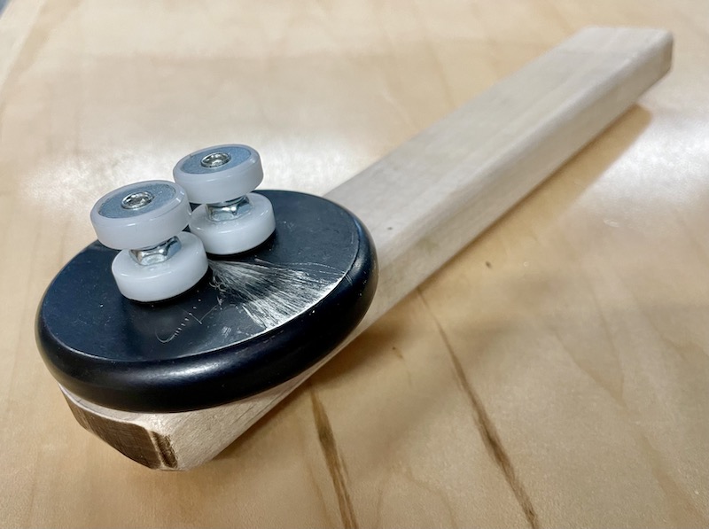
First I made this bending tool, which is nothing more than a normal edge rolling tool with the roller wheels doubled up and a short handle added. Two sets of rollers stacked up allows you to bend a flange 11/16" deep. The handle I made from a scrap of maple, and since I now have easy access to a router table I rounded the edges to make it easier to grip, but these are purely optional improvements.
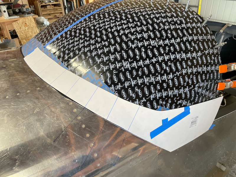
With the windscreen clecoed to the roll bar, I made a posterboard template of one-half of a fairing, with the front edge being right at the point where a line tangent to the windscreen intersects the fuselage. This took several iterations to get the shape just right, using a flat piece of scrap aluminum to determine the windscreen/fuselage intersection point. After this picture was taken I trimmed the top down to about 3" from the fuselage skin; it will get shaved down further later on.

The same template, reversed, fits adequately on the opposite side of the windscreen. Note the reference lines marked on the template and fuselage to help align the pattern in the same place between progressive trimming sessions:
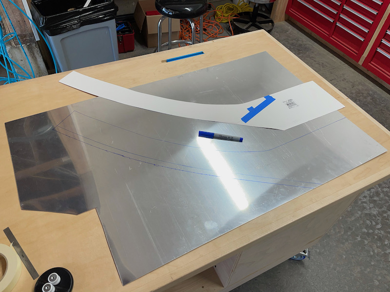
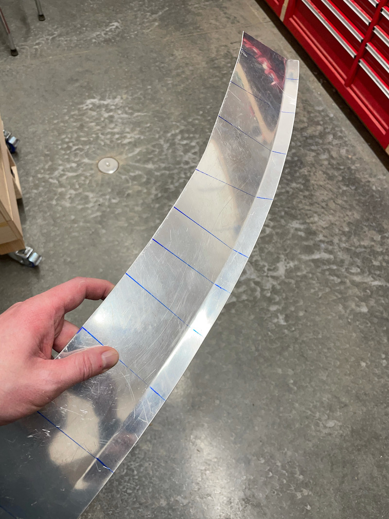
I traced the template onto a sheet of 0.032" alclad, then extended the forward edge a further 11/16":
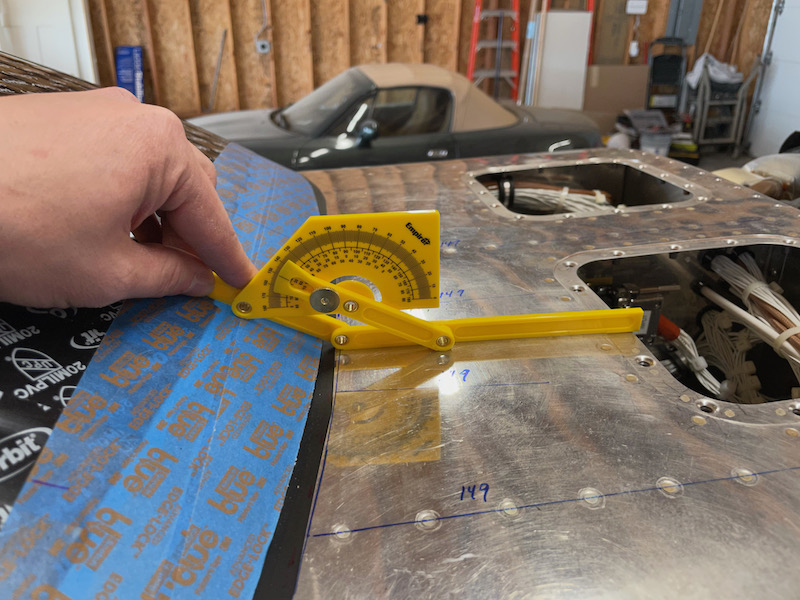
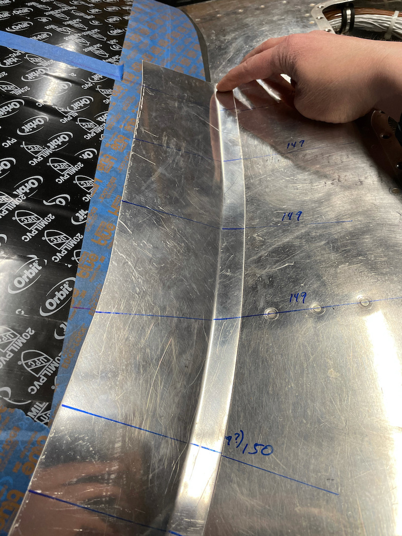
I used an angle finder to measure the angle between the windscreen and fuselage every few inches, and marked the resulting angles on the fuselage and on the template:
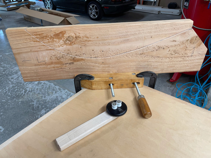
Then I took a piece of foam board and trimmed and sanded it until it fit the contour of the bottom of the windscreen, along a straight line from the center of the windscreen out to the corner. I don't think the actual path this follows is super critical, as long as it spans as long of a distance across the windscreen as it's possible to trace in a straight line.

I used the foam template as a pattern to cut the same curve into a scrap piece of 2×10 that I had fortuitously been saving. This makes a jig that the fairing halves are clamped into while you form the mounting flange.
Then it's just a matter of clamping one fairing half into the jig and working the rolling tool across the flange, slowly and smoothly bending a little at a time. The jig makes the fairing conform to approximately the shape of the windscreen/fuselage intersection, while you bend and stretch the metal at roughly right angles to the jig. You just roll the tool back and forth for a while, applying a steady bending force, then take the part out of the jig and test-fit. Take note of the spots that have been bent sufficiently and those that still need more work, clamp it back in the jig, and repeat.
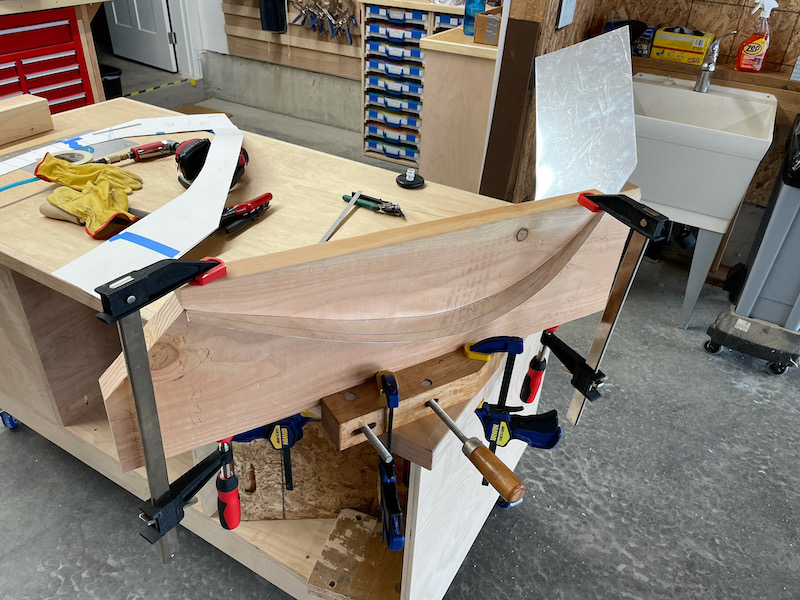
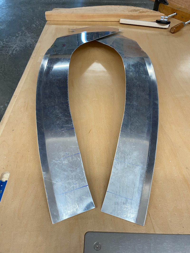
It took some sweating to get to this point, but surprisingly it wasn't all that difficult to create this three-dimensional curve:
At this point I started to think I might be able to make this work. It took a couple hours to make these parts, but the fit at this stage was really starting to look promising. I did sort of pay attention to the angles I'd measured earlier, in the sense that they helped me know in advance which spots would require the most bending, but I didn't intentionally attempt to make the bend angles along the fairing match the measured angles on the airplane. If you think about it, a perfect bend angle would probably be too much, as you want a small amount of springback to prevent the fairing from lifting away from the plexiglass.
Anyway, I just kept after it until I had two mirror-image fairings that each seemed to fit pretty well:
Up to this point I was just experimenting, and I hadn't done anything permanent. I figured if my test pieces turned out to be not so great, I'd either scrap them and start over, or give up on the entire idea and go with the default fiberglass fairing option. But things were going so well, I figured I might be able to pull this off after all. So, I bit the bullet and drilled one hole at the inboard end of the right-hand fairing, which I then drilled and clecoed to the fuselage. That in turn allowed me to continue to fine-tune the fit in the bending jig, with the cleco acting as a third hand to help keep the fairing pulled tight.
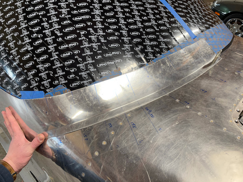
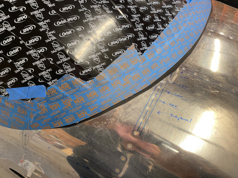
After a few more rounds of tweaking the bend angles I decided it looked good enough to keep going, so I marked the locations of the underlying subpanel and ribs in order to avoid putting a hole where it didn't belong. With careful rivet spacing you can either avoid the hidden structure entirely, or else place a rivet hole squarely in the center of a rib flange, as required.
I kept moving downward, alternating from side to side. At some point during this process I trimmed the inboard ends of the two fairing halves so they'd butt together, which allowed me to keep them both clecoed in place at the same time. That's important to do because the fairings somewhat change the shape of the plexiglass windscreen in areas where it needs to be pulled tighter to the fuselage; they're essentially giant version of the small metal clips you'd use with a fiberglass fairing. Doing both sides at once prevents any asymmetry issues resulting from the windscreen bulging to one side. Working my way outboard and down, I carefully held each fairing half tight to the windscreen and fuselage skin before drilling and clecoing.
Once I got to about the 45º point, I knew it was probably going to work, and my attention shifted to how the fairing halves were going to intersect the line of rivets along the longeron. Some judicious trimming of the forward edge enabled me to fine-tune where the row of fairing rivets would cross the longeron, ensuring that the rivets in the corners of the fairing would land cleanly between two existing longeron rivets. I very carefully marked the locations of everything I needed to avoid, triple-checked the fit, and drilled the fairings through the fuselage skin and longerons:
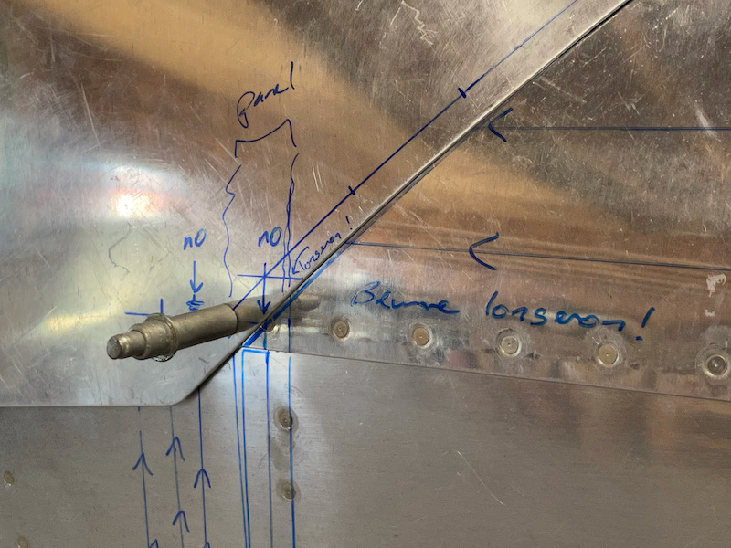
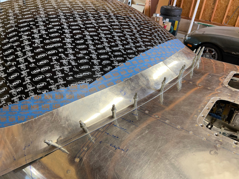
From there it was a simple matter of drilling all the remaining rivet holes. Happily, I was able to keep all of the skin holes above the longeron forward of the instrument panel, which means I won't see any unsightly rivet tails poking through the skin in the cockpit:
I'm really pleased with how this turned out. The aluminum fairing halves are almost a perfect fit to the windscreen, and the flange is almost a perfect fit to the fuselage. This process took me a couple of weekends, fumbling my way forward, but in retrospect it was so simple that I could probably do it again in half the time. I never thought I'd be able to achieve this kinds of result without first mastering all kinds of arcane metalworking skills, but to my great surprise my first "ehh, this could be a waste of time" test pieces ended up fitting perfectly the first time. And no sanding required!
I still need to trim the top edges, and fabricate a cover piece to go over the top of the rollbar, but that should be basic sheet-metal work, not the kind of obscure magic that produces compound bends.