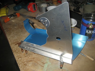
Time to start on the engine baffles, which form a box on top of the engine to direct cooling air down through the cylinder fins. Everything I've ever read about the baffle kit has mentioned weak instructions and poorly fitting parts. However, Van's must have re-engineered the baffle kit sometime recently, as my baffle parts are CNC-punched and the instructions feature computer drawings. They are still confusing and contradictory, but at least the pictures are pretty!
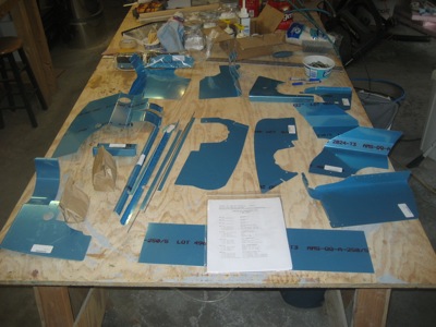
Lots of sheet metal parts:
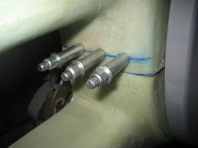
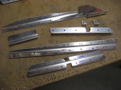
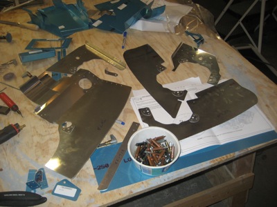
You start by chopping some partially pre-cut angle stock into six or seven separate pieces, which will become brackets and stiffeners:
Various pieces have stiffeners and doublers attached. I riveted on the bolt-hole doublers as instructed, but I am holding off on riveting anything else until I have a better handle on what's going to fit and what will need modification.
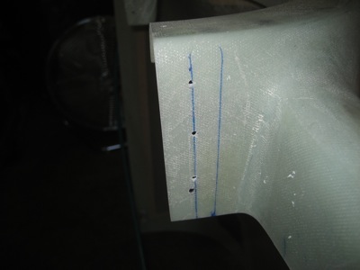
It didn't take long to get crosswise with the plans… on the second page, they want you to start cutting and drilling the port-side aft baffle for mounting the oil cooler. However, at this point you don't know how tall the baffles are going to be, which means you also don't know where the oil cooler should be positioned vertically. Not to mention, I'm not sure I'm even going to be able to put the oil cooler on the baffles anyway (see below).
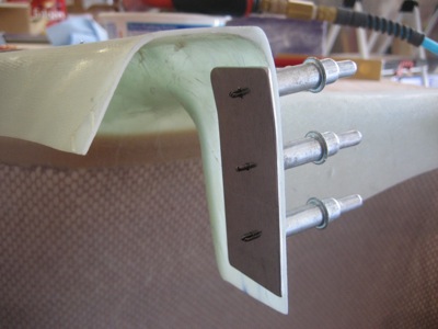
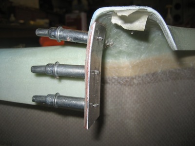
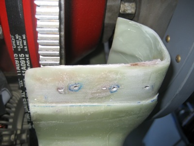
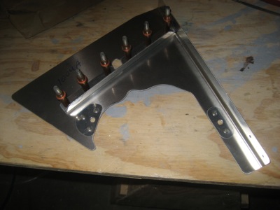
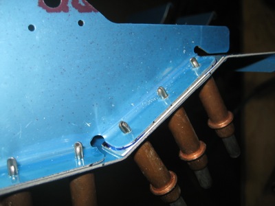
I decided to leave the oil cooler stuff along and skip ahead in the baffle plans. In this area at the right-side aft corner, the preformed parts don't quite match up:

Rather than force the parts together – a recipe for cracking – I made a little 0.032" spacer to fill the gap:
Many hours later, I now have most of the bolt-hole doublers riveted to the baffles, and about half the baffle pieces deburred. Smoothing the edges of all those funny-shaped parts is highly tedious.
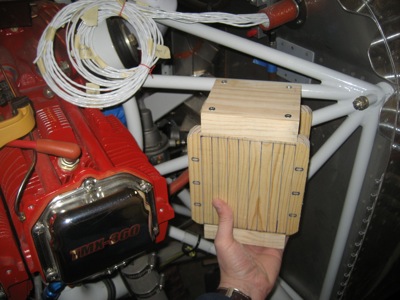
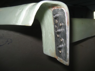
This is my oil cooler… it's a Stewart Warner 8432R, which is a bigger version of the 8406R, which is itself a higher-quality replacement for the no-name cooler that Van's will sell you. I let the guy from Pacific Oil Cooler talk me into buying this one – the argument being that it's easier to fix an installation with too much cooling capacity than too little. That does make sense, but if I'd known how little room I'd have to mount it, I might have gone with the next size down!
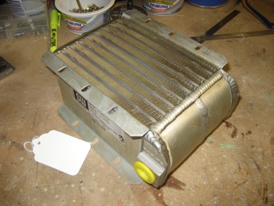
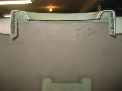
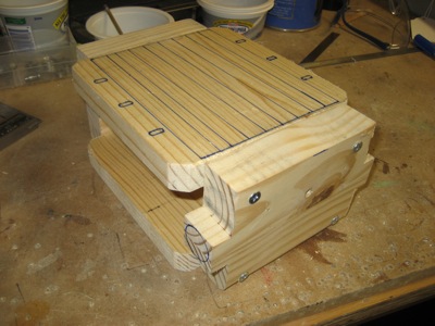
The oil cooler is beautifully made – look at those welds! – but it's also heavy and expensive and kind of fragile. I didn't want to risk dropping or damaging it while experimenting with mounting locations, so I built a dimensionally accurate stand-in out of scrap wood. If the wooden oil cooler fits, the real one will too.
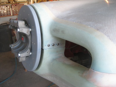
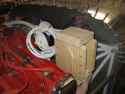
The plans want you to put the oil cooler here, on the baffle behind the #4 cylinder. I might be able to make that work, although the flimsy sheet metal baffles will have to be strengthened considerably to properly support this brick.
Another possible idea is to attach the oil cooler to the engine mount instead. That would certainly be easier from a vibration point of view, but then I'd also have to come up with a way to duct a sufficient volume of air to it, while still fitting within the tight confines of the cowl. Hmm…