Archive for the ‘Baffles’ Category

Installed and sealed baffles

Monday, May 27th, 2013

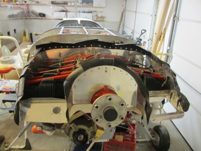
One of the chores I'd put off earlier, since I knew I was going to have to remove the baffles to tear down the engine, was the messy job of sealing all the small gaps between the baffles and engine with RTV. Well, now that the engine is all put together again, it's time to bolt on the baffles and get messy.

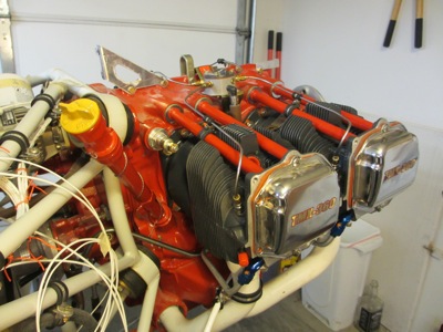
The #3 cylinder baffle (aft starboard corner) was already installed from a previous job:

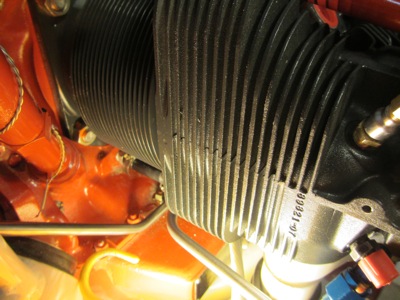
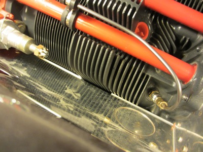
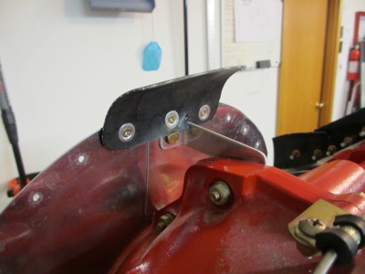
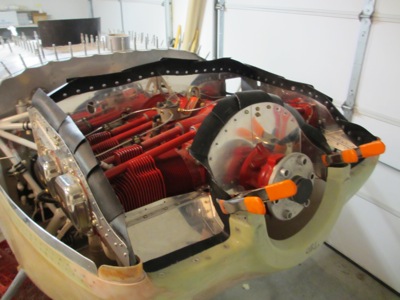
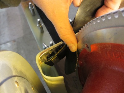
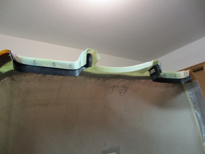
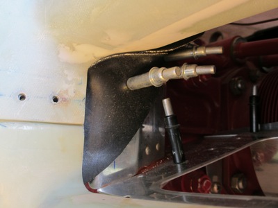
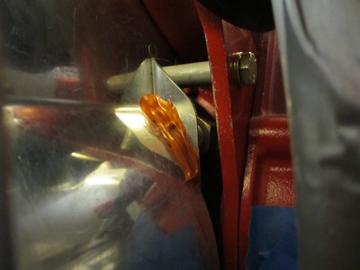
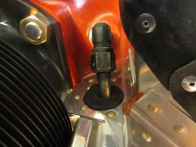
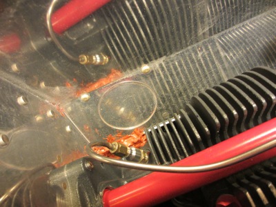
I discovered a rather disconcerting problem with the baffle on the #4 cylinder (aft port corner). It seems that I ended up with a gap between the baffle and cylinder barrel at the junction with the cylinder head, due to a deadly combination of carelessness, cluelessness, and the prepunched holes being drilled in a less than ideal spot. You can see the gap as a bright spot in the left-center of this photo, revealed by a light placed behind the baffle. This clearly won't do, since lots of precious cooling air will end up spilling through that gap instead of going through the cylinder fins and doing useful work.

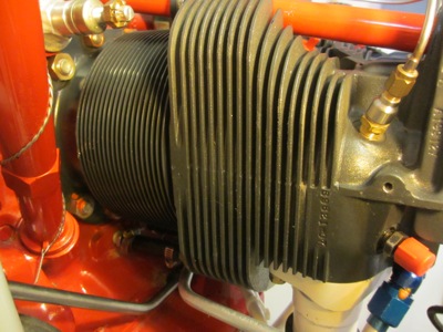
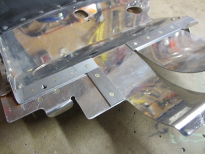
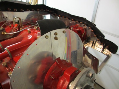
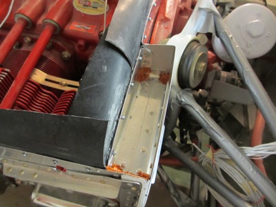
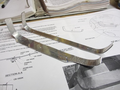
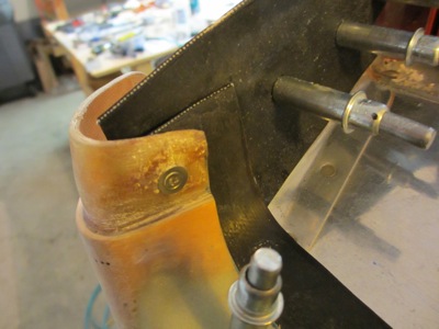
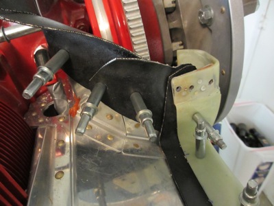
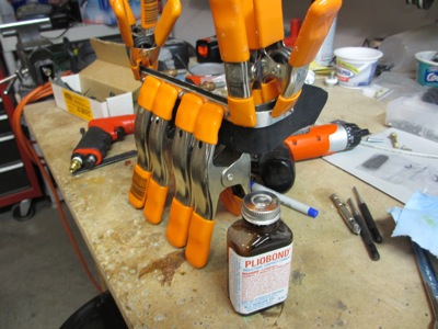
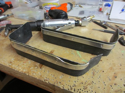
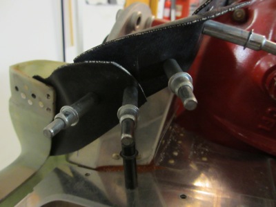
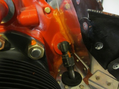
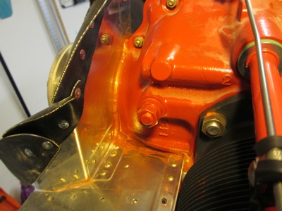
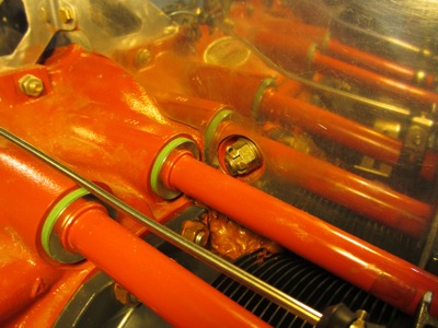
The complete solution to this problem would be to remake the inboard portion of the #4 cylinder baffle, which I still may do someday if it ends up being a problem. But in the meantime, my partial fix was to use some scrap aluminum angle to fabricate a little sealing plate, to cover over the worst part of the gap, and seal up the rest with RTV as best I could. I don't know if this will entirely work, but it was relatively easy to do (or at least as easy as working in the confined spaces on and around the engine ever is). In this photo you're looking forward and to the right; the bolt captures the plate, the spacer holds it in place against the baffle, and the glue does the rest.

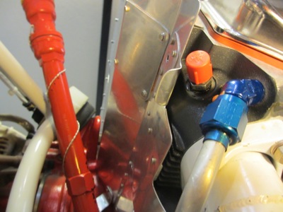
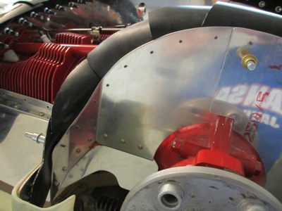
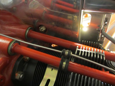
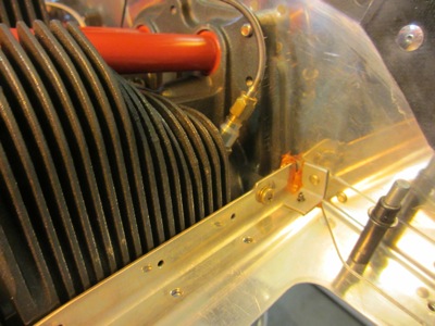
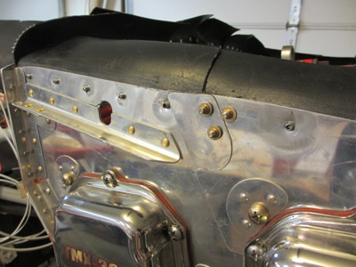
The prop governor line passes up through the front starboard baffle, through this grommet which was a royal pain to install because the stackup of materials is so thick here. Next time I might think about fabricating some kind of seal plate with a smaller grommet in it, which could more easily installed with a couple strategically placed screws.

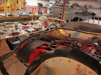
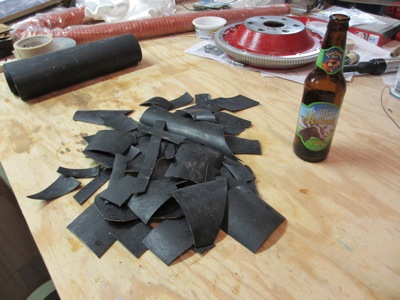
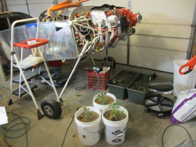
At some point during this process we had an unexpected snowstorm (in May!) that caused Mary to haul all of her garden containers into the garage. I thought this was a funny picture:

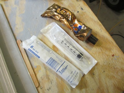
When RTV has to go into a particular location without turning into a total disaster, I prefer to use a syringe to direct the flow. The 6 mL size is just right; I buy them at the farm store up the road.

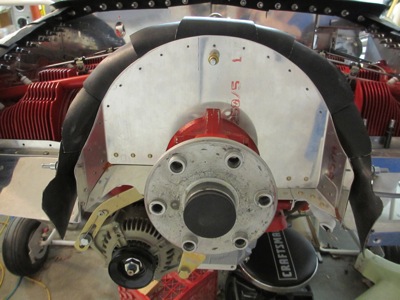
RTV applied between the #1 (front right) cylinder baffle and the engine case:

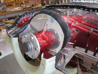
Between the #2 (front left) cylinder baffle and the engine case:

A small spot at the outboard corner of the #2 baffle where it attaches to the cylinder head:

Filling gaps at the inboard corner of the #3 cylinder baffle where it meets the crankcase, below and behind the oil pressure regulator: (reflections make it look messier than it is)

At the outboard corner of the #3 baffle where it mates to the cylinder head: (reflections again)

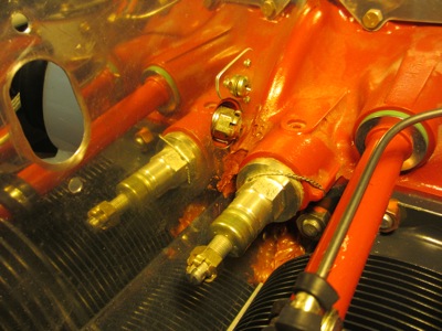
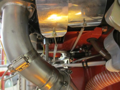
Filling a gap where the shape of the baffle doesn't completely match the junction of the #4 cylinder barrel and the crankcase:

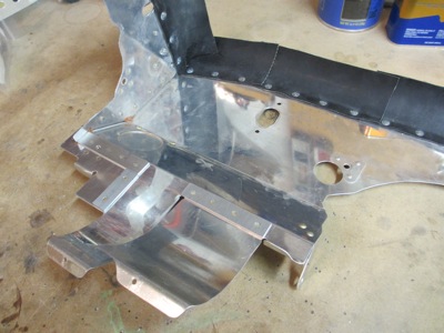
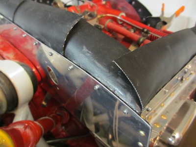
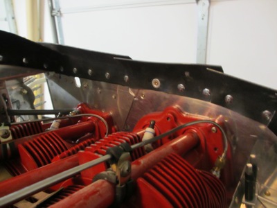
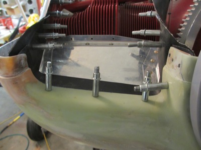
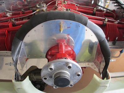
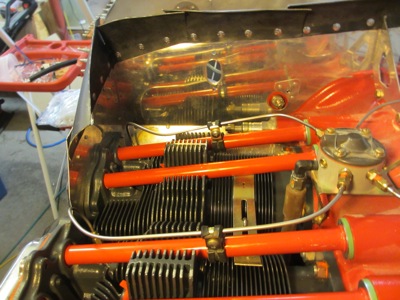
I installed the little splice plates that join the forward and aft baffle halves at the slip joints:

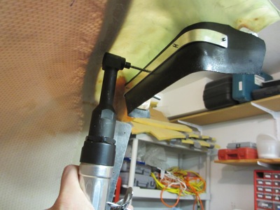
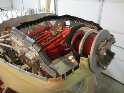
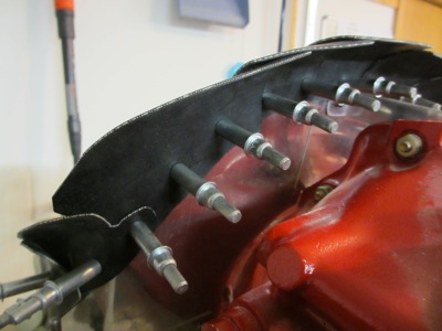
And, installed the baffle tension rods:

The baffles are now installed on the engine for good! They should not have to come off again unless I discover some kind of unexpected cooling problem, or if I have to tear down the engine again. Please, let's not do that again already, I can't afford to have that much fun.

#3 cylinder cooling modification

Monday, May 27th, 2013

Yes, I am still working on the airplane! My excuse for not posting any updates for a while is that I've been ridiculously busy at work, and also I've been jumping back and forth between separate but overlapping firewall forward projects that haven't really lent themselves to turning into a single writeup. So beware that the photos accompanying the next few posts may show multiple separate things happening at once. Don't panic.

Here's the back of the engine, viewed from the starboard side. The cylinder closest to the camera is #3.

Here's a closeup of the back of cylinder #3, which is the intake side. The issue on the RV's is that the cooling fins here are really shallow, and in fact are partially blocked in places by the design of the cylinder casting. The RV baffles sit hard up against the aft face of the cylinder, which has the effect of choking off a lot of the air that is unable to pass from the top of the cylinder to the bottom through the blocked fin passages.

Here's another view with different lighting, in which you can see the problem. The fin area at the center of the photo is very shallow, and the portion of the fins in the lower right (near the intake valve) is blocked entirely:

The traditional approach to ensuring adequate airflow through the cooling fins is to add a washer between the baffle and the cylinder, at the screw hole shown on the right side of the previous photo. This probably works, but opens up a gap along the entire back side of the cylinder, which wastes cooling air. A better approach is to form a duct in the baffle to let air "jump over" the blocked fin passages. Since my baffles were already finished and fitted, I chose to address this by riveting some strips of 0.090" scrap aluminum to the inside face of the baffle. This isn't as good as a formed duct, but it was easier to accomplish:

Alternate view showing the spacer strips. The inner portion over the cylinder barrel is blocked off, since the fins there are plenty deep, and the outer portion is blocked off since the fins are either adequately deep or nonexistent.

Here's what the channel looks like when the baffles are installed on the engine. Air can go down through the channel formed by the riser strips, but is forced back through the lower cylinder fins by the circular wrap that goes underneath the cylinder. As a result, the air is able to do some useful work cooling the engine, instead of being blocked. To the left and right, the air goes down between the cylinder fins as per normal.

Viewed from underneath, you can see the vertical spacer strip that's necessary to keep the air from squirting outboard instead of staying between the cylinder fins and continuing downward. Although it looks like some of the lower outboard fins are "orphaned", i.e. cut off from cooling air, the design of the cylinder head and stock baffles would have stifled these vestigial fins anyway, so I don't think any cooling capacity is lost by doing it this way.

On to the final baffle installation. This was an easy mod to do, once I understood the geometry of the airflow and the nature of the problem to be solved. If it helps prevent cylinder #3 from running too hot, great – otherwise, it should be no big deal to remove these spacers later down the road if I need to address this area again.

Finished baffle seals

Sunday, April 15th, 2012

Finally, I have the baffles all built and the rubber seals all fabricated. Nothing left to do next except attach them together. I started with the upper piece on the forward crankcase baffles… this one gets attached with screws instead of rivets, since it spans two separate baffle pieces and might someday need to be removed:

A view from the other side… I may replace these nuts with all-metal locknuts later, after my next parts order:

To keep air from leaking between the aluminum baffles and the rubber seal strips, I put down a thick bead of black RTV before I started riveting. This also means that I didn't get any pictures of the process, since my hands were too filthy to hold the camera.

Fast-forward a couple hours… my hands are all black with glue, and all the rubber pieces are attached to the baffles with large-head blind rivets. I cleaned up all the squeezed-out RTV and made sure there was an adequate bead all along the top seam.

One hole on either side gets a screw and nut instead of a rivet, so I can peel back the associated rubber strip to install or remove the metal seal tabs.

While I was in sticky-finger mode I dabbed some orange RTV in the gaps and tooling holes around the top of the oil cooler area. Don't ask me why I used two colors of glue.

Here's the finished product. The next step after this is "go all around the engine and seal every little gap between the engine and baffles with RTV", but I'm not going to do that just yet. There is an AD out on my ECI cylinders that I'll have to deal with first, which unfortunately means everything will have to come apart one more time before it's all said and done.

Finally, done with the baffles! I collected a ton of scrap cuttings of rubber seal material from around the garage – and this is probably only about half of what I generated, not counting what's already gone into the trash.

Oh, and tonight's beer is an excellent spring seasonal from a brewery just down the road from my airplane factory.

Lower cowl baffle strips

Sunday, April 8th, 2012

On either side of the lower cowl, you're supposed to attach a piece of rubber baffle seal material to bridge the gap between the cowl air intake lip and the metal baffles. These are the only two rubber pieces that are attached to the cowl instead of the baffles themselves. I first made some aluminum backing strips to fasten the rubber to the cowl. Note the special shape of the nearest one, which is necessary to preserve proper edge distance on the left inlet (the one that's mostly taken up by the air filter).

Once again the angle drill is worth its weight in… something heavy and expensive. You can see in this photo that I drilled an extra hole on the inboard end of each attach strip, so I could put a screw on the "upright" portion. I found that helped the rubber seal stay in place a little better when installing the cowl.

Here's what one of these seal strips looks like when being test-fitted. Since the bottom cowl is installed from below, these strips have to pass up and over the metal baffles as you raise the cowl, which can be awkward. You want to start with an oversized piece and gradually cut it down until you find the balance point between too hard to install and not enough overlap with the metal baffles. I ended up with about 1/2" of overlap, which is similar to other RV's I've seen. These strips have also been a pain in the rear on every other RV I've ever taken the cowl off of, so I think I must have them sized about right.

I added a countersunk screw at the outboard corner on each side, the better to keep the rubber seals from folding up when installing the cowl. This was only possible thanks to the extended attach flanges I laid up a while back. The screw and tinnerman washer are hidden beneath the upper cowl when it's installed.

Here's how it looks at the inboard end:

The cowl seal overlaps and sits on top of the "ears" on the crankcase baffles (exaggerated here for clarity). You can sort of see the upper leg of the metal attach strip here too:

That's the last of the rubber baffle seals to be fitted! Everything from here onwards is assembly, at least as far as the baffles are concerned.

The plans tell you to permanently attach the mounting strips to the rubber seals with Pliobond. What they don't tell you is that this stuff is also the most evil, nasty, noxious, horrible-smelling gunk on the planet. Worse than Proseal even. I had to vacate the garage while it cured so I wouldn't get gassed.

The result, a couple days later:

I countersunk the cowl for #6 tinnerman washers and attached the seal strips with screws and nuts:

Crankcase baffle seals

Saturday, March 17th, 2012

The baffles on the forward part of the crankcase, just behind the prop hub, are deceptively difficult to get shaped correctly. So, it should come as no surprise that the associated rubber seal strips are also hard to get just right. After much trial and error, I ended up making the seals out of nine separate pieces of material in order to get them to lay against the upper cowl without wrinkling. Also, pay particular attention to the "ears" at the front:

Those ears have nothing to do with directing airflow – instead, they are there so you can tuck the rubber seals inside the inner face of the spinner opening on the bottom cowl, to prevent the oncoming air from peeling them back and trying to turn them inside out. I'd seen this before on other RV's but never really comprehended what I was looking at until I was deep into the baffle process.

Here's what it looks like with the top cowl on:

I had an especially hard time figuring out how these seals were supposed to go, so I'll try to help out the next guy by posting a few more detail photos of this area. When you get to this part of the build, you'll know what you're looking at.

Segmenting helps the rubber follow the shape of the top cowl:

Adjacent pieces overlap from front to back to keep the air from getting underneath:

Tabs and carefully-cut angles help go around corners: