Archive for the ‘Ailerons’ Category

Aileron alignment jigs

Thursday, August 10th, 2023

The next major project will be to fit and install the wingtips, but first I need to find a way to hold the ailerons in the correct position so I can make all the trailing edges line up. The plans are fairly silent on how to do this – probably they expect that the bellcrank alignment fixture will suffice. But I wanted a more positive means to align the ailerons with the flaps, so I knocked together these jigs out of materials I had on hand:

The center piece is made of 1/4" nylon, strictly because I had a chunk of it laying around, and the angle pieces are lined with UHMW tape so they don't scratch the skins. When installed, they hold the ailerons tightly in line with the flaps, with hardly any play:

On the bottom side, the bungee cord hooks around the inboard aileron hinge and keeps the alignment jig from backing off:

I copied this design from a type of gust lock I've seen used on DC-3s… in fact, I may eventually repurpose these as gust locks for the RV. In the meantime, I now have a way to hold the ailerons in the proper position for fitting the wingtips.

Installed and rigged ailerons

Sunday, April 9th, 2023

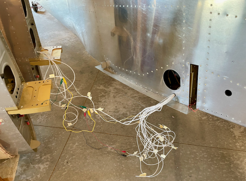
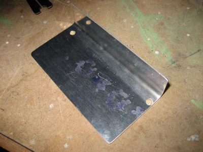
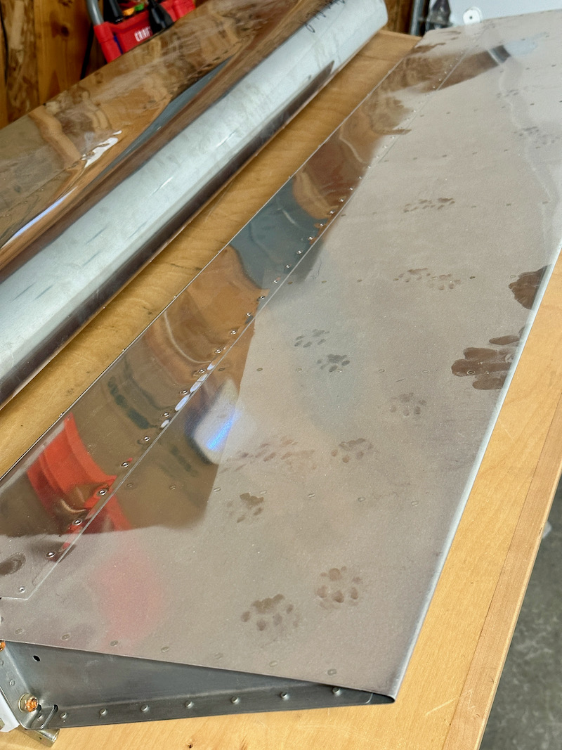
I brought the ailerons down from the attic and cleaned off the worst of the dust – but not before being perplexed by the critter tracks I found. Let's hope that happened during the time I had them stored in a neighbor's hangar:

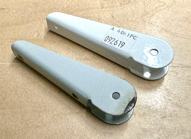
One of the steel hinge brackets had developed some rust, and though I could have cleaned it up and repainted it, I decided it was easier just to replace it with a new one:

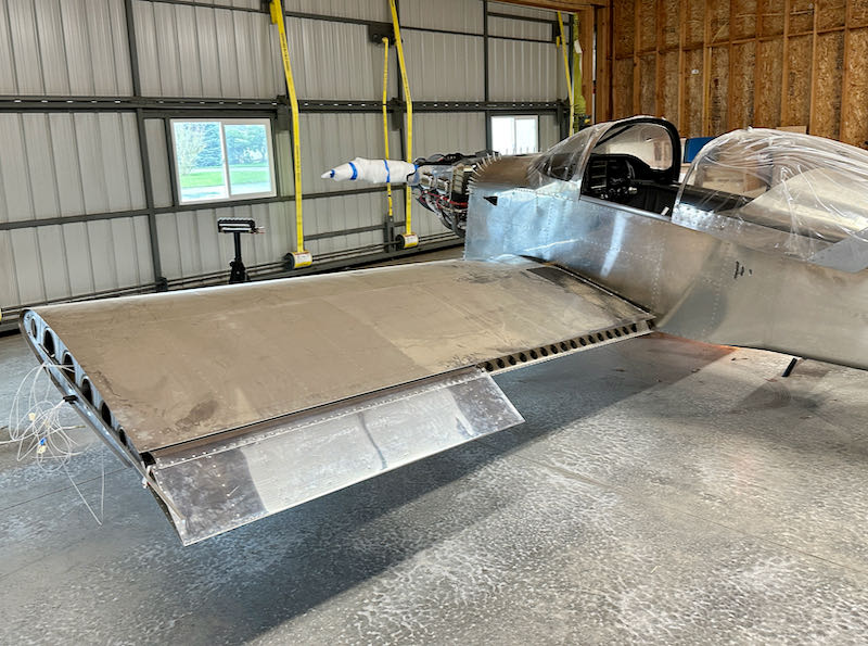
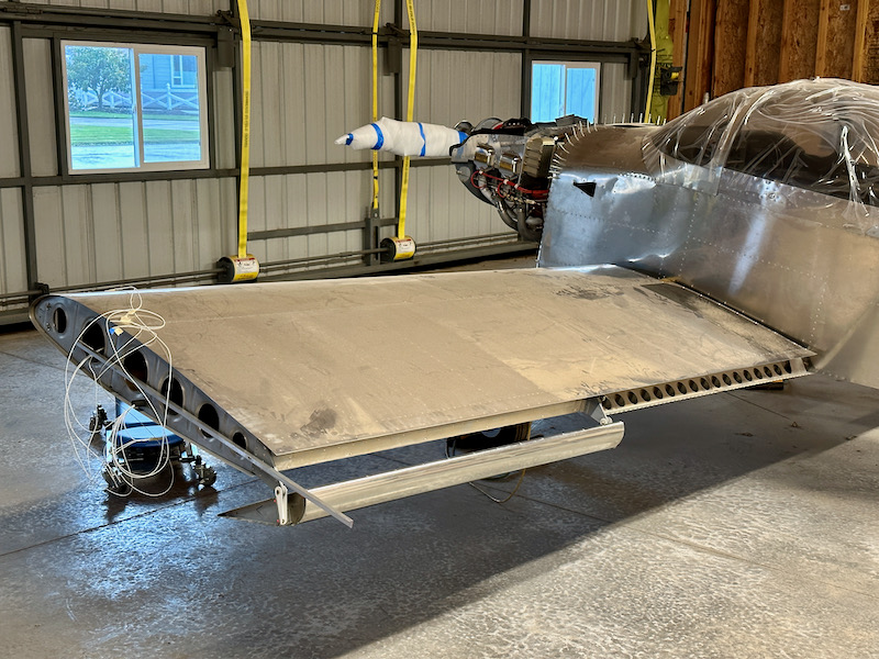
With all that cleaned up, I proceeded to hang the ailerons on the wings:

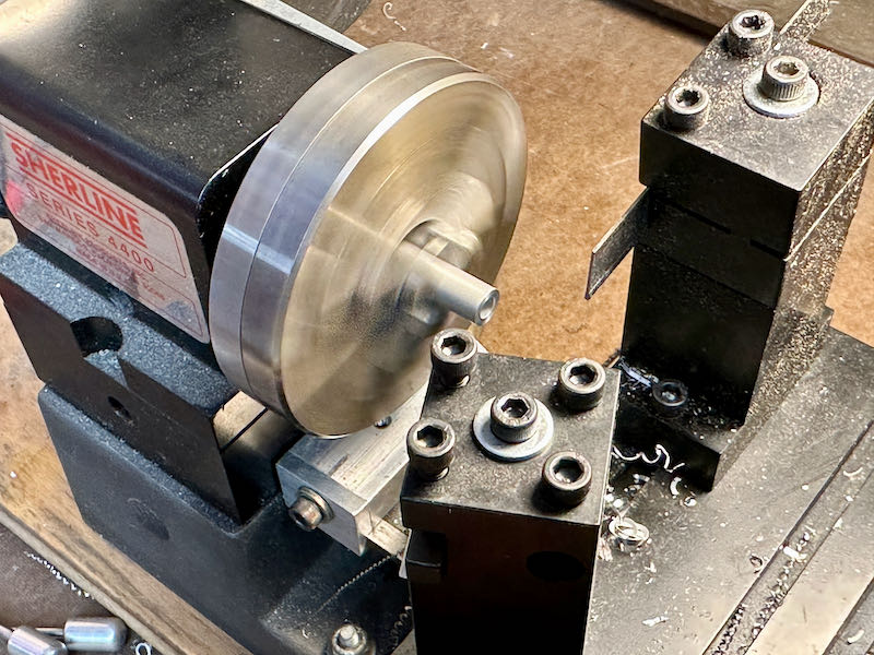
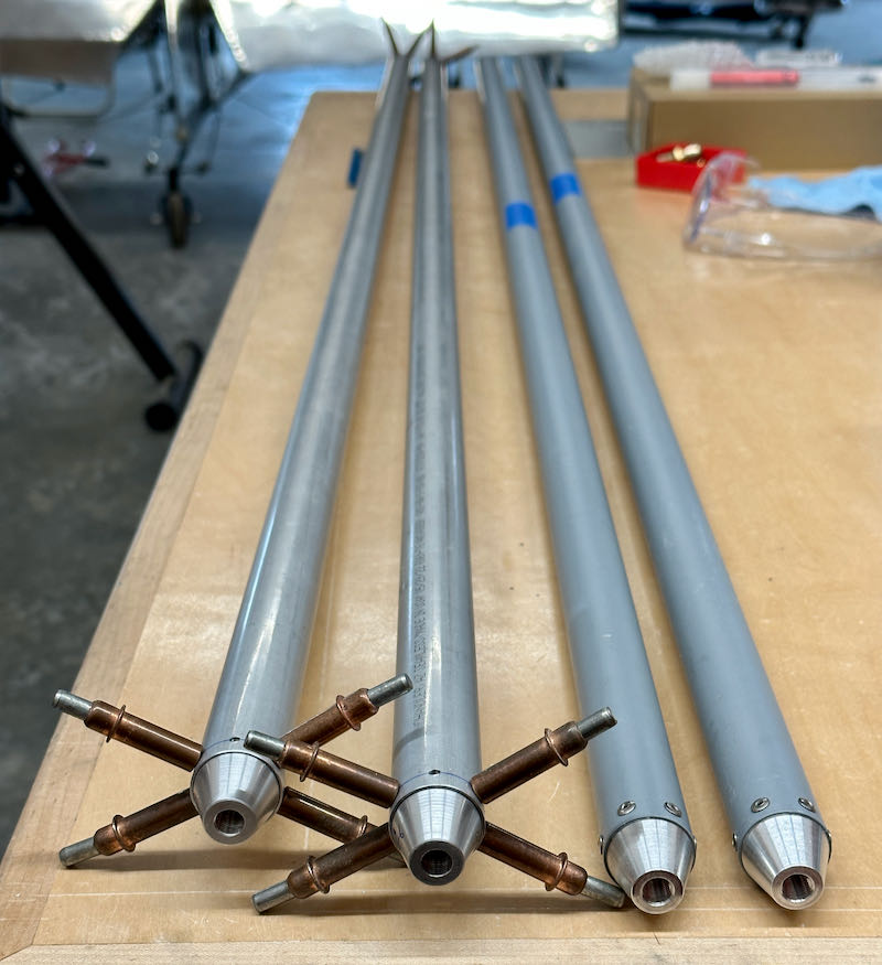
I made the required hinge spacers on my little lathe, which is great for this kind of job:

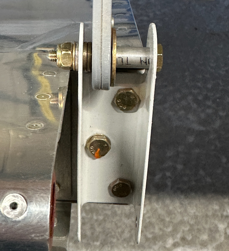
This is what the hardware stack-up for the outboard hinge brackets looks like. (Note: many of these photos taken during the test-fitting process show loose fasteners and non-aviation hardware. I'll fix everything up properly when I'm done fiddling with things.)

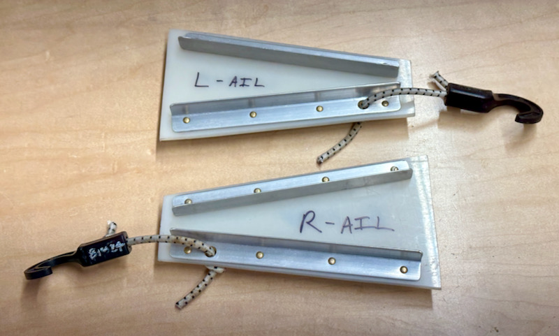
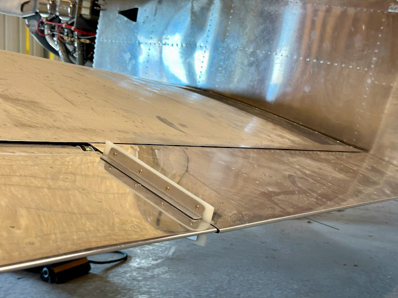
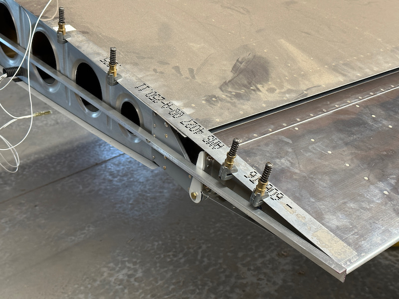
I made a set of alignment tools out of hardware-store aluminum and bolted them to the tip rib. It helps to put some spacers between the angle and the rib (I used the lathe again) to prevent it from being bent by the outboard hinge bracket. That would throw off your aileron alignment and lead to problems later. You can also see here how I am holding the aileron in place with a strip of scrap aluminum and some cleco clamps:

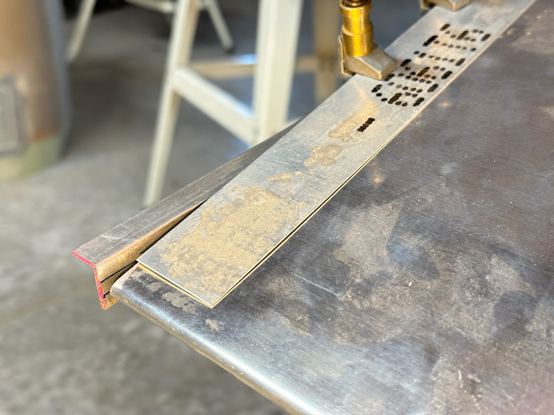
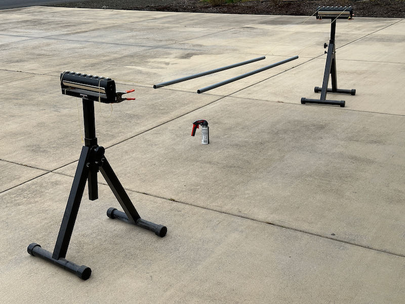
This is an easy way to solidly hold the ailerons in the right orientation (tip aligned between the blue lines) while I work on other parts of the flight control system

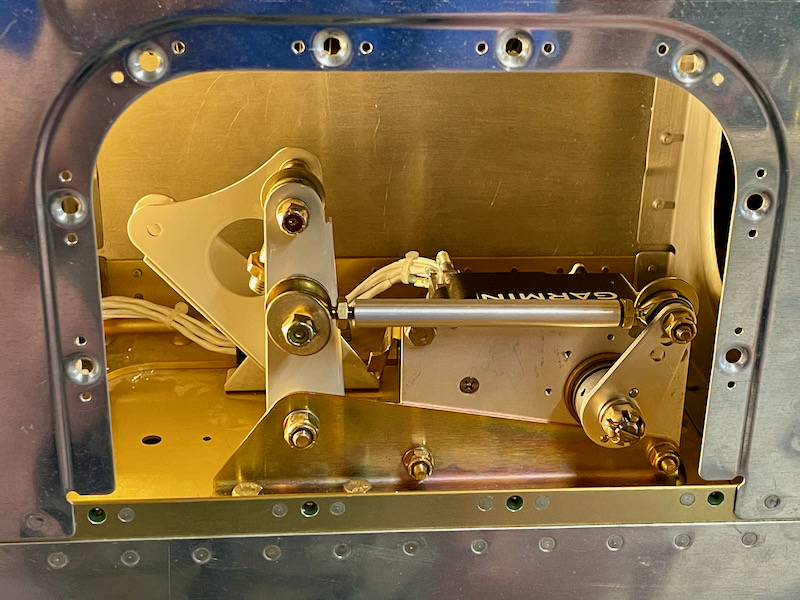
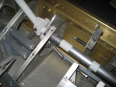
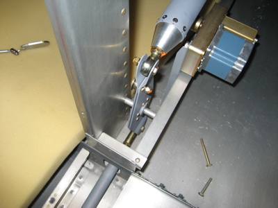
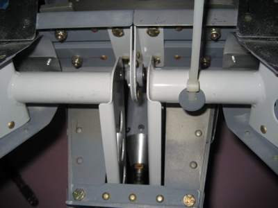
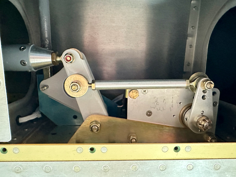
This photo is looking up through the outboard access hole in the left wing. The W-818 pushrod runs from bottom to top on the left side, and the W-716 pushrod goes off to the left. Visible in back is the W-730 alignment jig holding the bellcrank in the right position. The idea here is that you use jigs to align the bellcrank and the aileron, then adjust the W-818 pushrod to connect them.

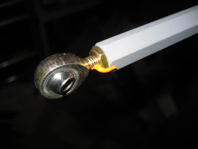
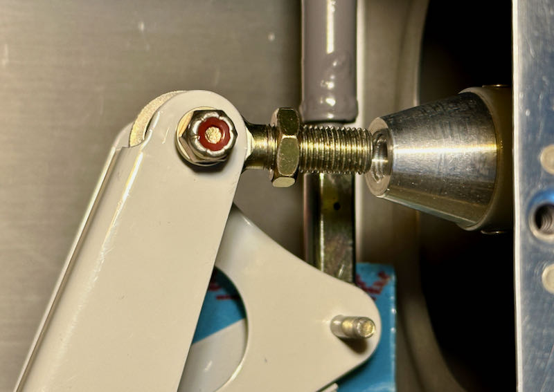
Although I fabricated my W-818 pushrods using the dimensions shown in the plans, they ended up slightly short. Judging from the many similar forum posts I've read, this is a common occurrence – it would be best to make them 3/16" or even 1/4" longer, material permitting. I solved the length problem here by switching the jam nuts to AN315s, which are 1/16" thicker than the default AN316s (a modification approved by Vans customer support). This ensures that no matter how the pushrod tries to unscrew itself, the worst-case rod end bearing will still have more than the minimum amount of thread engagement.

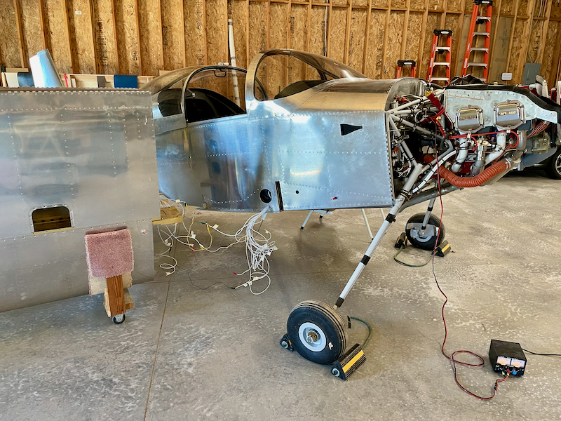
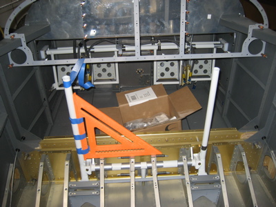
Inside the cockpit, I built a temporary jig to align the control sticks vertically, using a collection of woodworking squares which are screwed to a board clamped to the spar:

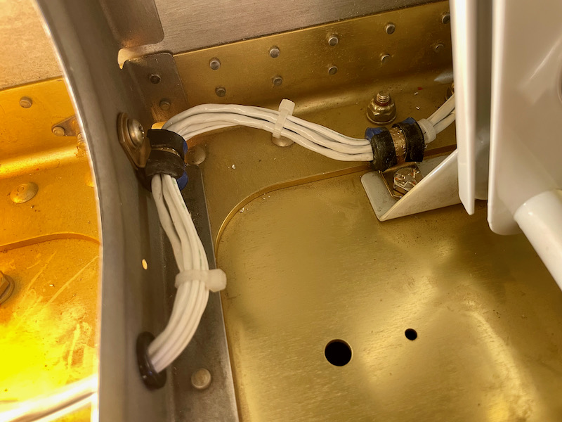
I maneuvered the W-716 (transverse) pushrods into the wings, adjusted them to fit between the control sticks and the aileron bellcranks, and then got a rude surprise. Although I built them exactly to the length specified in the plans, they are way too short, and will allow the rod end bearings to unthread themselves – an obviously unacceptable condition:

Judging from the many forum threads on this topic, this is another well-known plans error that has caught plenty of other builders just like it caught me. How incredibly aggravating. So now I'm on the hook for $100 worth of parts and the time required to build a new set of pushrods. At least nowadays I'm close enough to the factory to save on what would otherwise be the exorbitant cost of shipping long pieces of tubing. The new parts will be 7/16" longer than the plans dimensions:

These aluminum pushrods are trivial to build, but they end up taking a while due to all the priming required, especially in the winter. I flooded the interior of the tubes with 7220 spray primer and allowed them to dry for several days, then suspended them on strings and primed the outside:

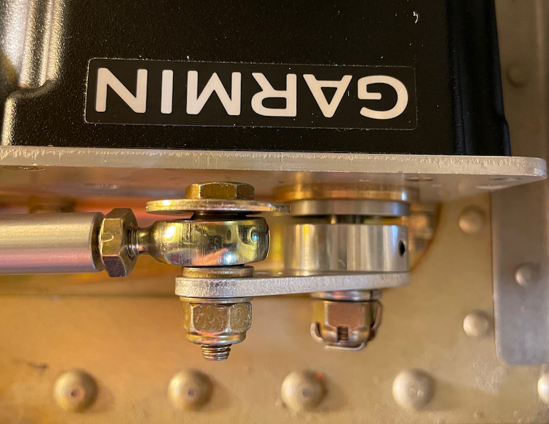
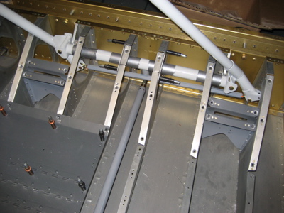
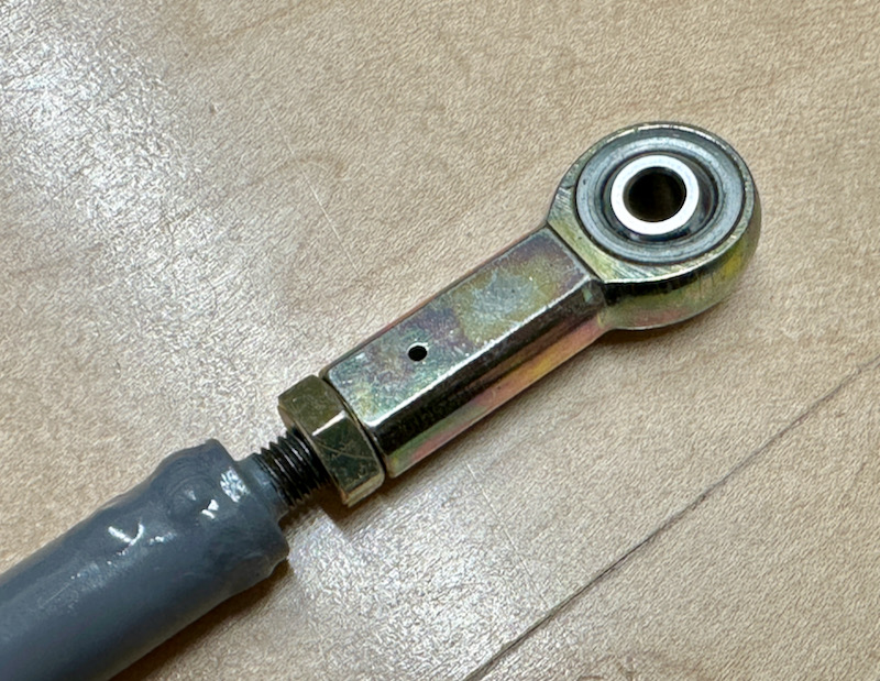
Finally I riveted on the end caps, inserted the bearings with their jam nuts, and slid the new pushrods into the wings. The result is a perfect fit that can't possibly come undone. In retrospect I could have made these 3/8" longer rather than 7/16", but this will work fine. This photo shows that there are still plenty of threads engaged in the worst-case condition where the other end is screwed all the way in:

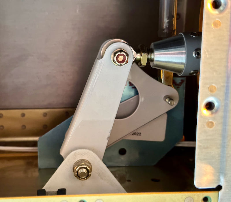
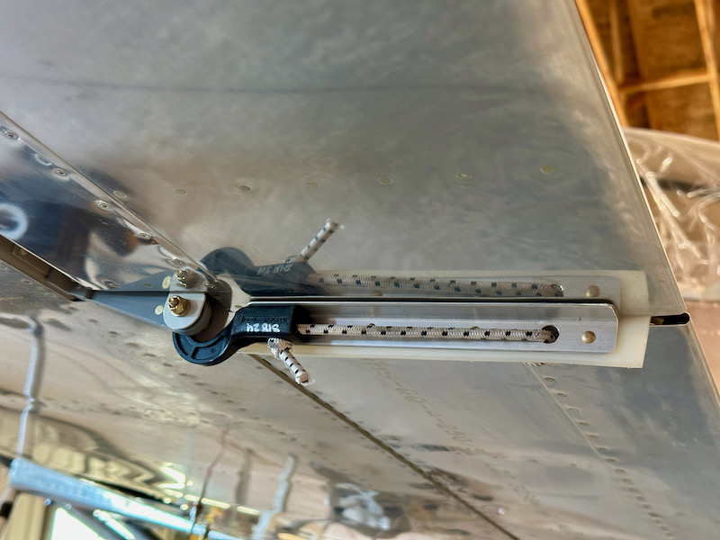
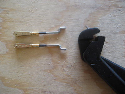
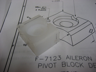
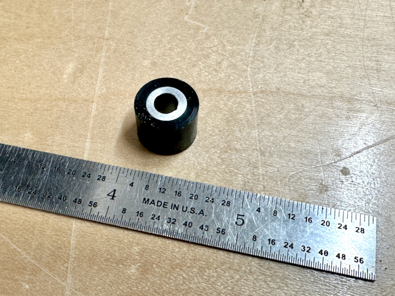
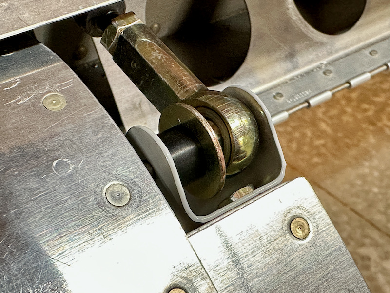
With the left and right ailerons finally connected together properly, I was able to fabricate the control stops. The plans call for a set of aluminum angle pieces riveted to the hinge brackets, but I wanted to try the popular method of using plastic bushings on the pushrod attachment bolts instead. I happened to have some black Delrin stock on the shelf, so I turned a pair of 1/2" diameter bushings with an aluminum spacer in the middle to handle compression:

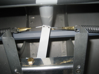
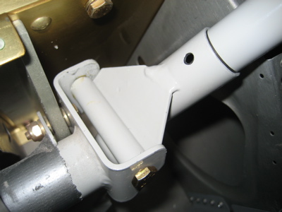
This is what the aileron stops look like when installed – the black Delrin ought to be good for UV resistance:

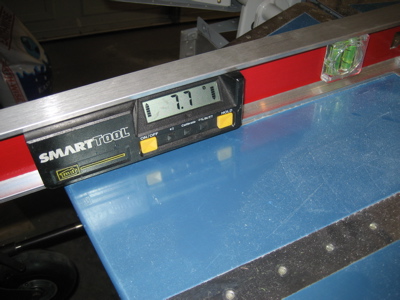
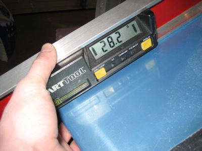
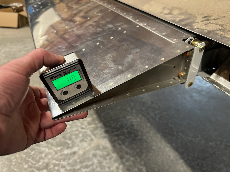
It turns out that – for my airplane – the 1/2" diameter stops are an ideal size. To check the aileron travel I aligned the ailerons with the tip jigs and set my digital angle gauge to zero with the ailerons neutral:

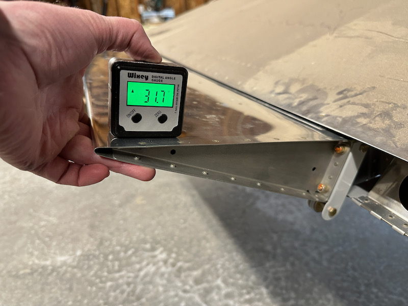
The ailerons on both sides hit the up-stop just shy of the 32º maximum limit specified in the plans:

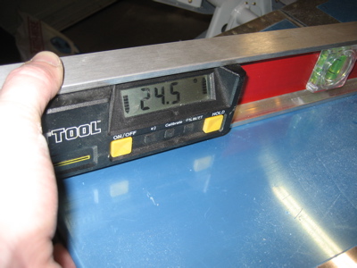
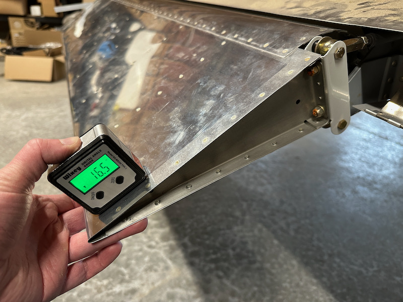
Similarly, the amount of down-travel is well past the minimum and just under the 17º maximum:

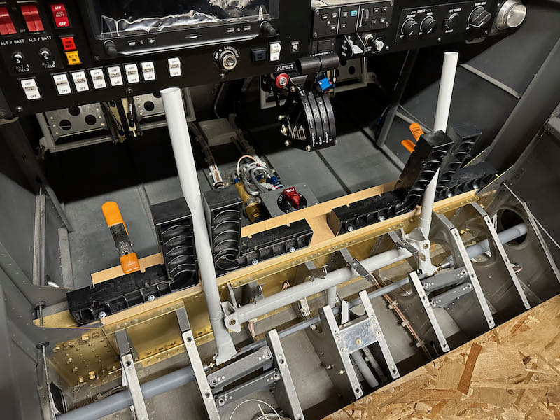
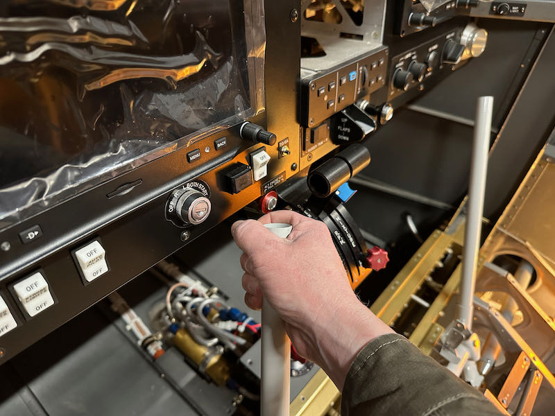
This also gives me my first chance to evaluate the total movement range of the control sticks inside the cockpit. Happily, neither stick comes close to hitting the throttle quadrant, which had been a concern:

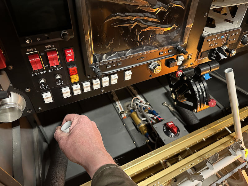
Similarly, opposite aileron travel provides plenty of clearance between the sticks and anything nearby. I'll still have to trim these shorter to accommodate my stick grips, but it's good to know what I'm working with:

I haven't torqued all the fasteners yet, as I will probably have to remove the sticks at least one more time, but for now all the primary flight controls are hooked up and usable – a great milestone:

Roll servo

Sunday, June 20th, 2021

I'm now trying to wrap up a number of to-do items on the wings, one of which was to install the roll servo (again). Doing this while working through the inspection hole is not as terrible of a job as it seems, as long as you have skinny arms and you can work by feel. I torqued all the servo mounting hardware and the bellcrank pivot bolt, but I left the servo pushrod hardware loose since its length will need to be adjusted later.

I ran new wires through the wing for the servo, and used a couple of adel clamps to keep them securely constrained so they won't get tangled up with the flight controls:

The pushrod hardware called out by Garmin makes for tight clearance between this bolt and the servo housing, but it's probably adequate. I'll check this again when I'm doing the final rigging and control checks.

To test the new servo and wiring I wheeled the wings over to the fuselage and made some temporary connections with alligator clips:

Technically, the wings are now "connected" to the fuselage!

All is well with communication to the roll servo, so I can check this off my list:

Finished aileron trim

Monday, May 28th, 2007

The plans call for the aileron trim springs to be connected to the servo arm by short lengths of 0.041" safety wire. I'm sure this solution works just fine, but I felt like doing something a little extra here. So, I made these little clevis links out of RC model airplane parts. They each consist of a piece of 2-56 steel pushrod material with a Sullivan clevis threaded onto one end and a Z-bend formed in the other.

Personal aside – when I was a kid, building balsa models, I used to dream of the day when I'd be so rich I could afford to spend fifteen dollars on a special tool for making perfect Z-bends, instead of making sloppy ones by hand with a needle nose pliers. Well, inflation has raised the price of a good pair of Z-bend pliers to $18.99, but in the scheme of things that doesn't seem like a whole lot of money anymore so I bought a pair just to have around for things like this.

Here they are installed in the airplane, with the servo arm in the neutral position. You can just barely make out the little steel clips that keep the clevises from popping open. I may actually come back and solder them permanently shut just to be extra safe.

Even with the servo arm and control sticks at each end of their total range of motion, the springs have a little bit of tension in them. That means they should never go slack and get tangled up on anything. Later on I can thread the clevises in or out later on as needed, although it looks like I got the lengths set pretty much right on the first time.

Pushroddery

Sunday, April 8th, 2007

Somehow I managed to get not much done despite having a three day weekend. Hmm.

I decided to install the electric aileron trim kit, but first I needed to get the control sticks and associated pushrods installed. I spent a bunch of time filing and grinding the inside of the passenger stick weldment, which had a big ugly weld bead clogging up the bore. Eventually I got it reamed out and smooth enough that the passenger stick could slip in and out.

I drilled a 3/16" hole through the passenger stick and weldment. There is a service bulletin that advises you to put a bolt through here, making the passenger stick non-removable. Since that would defeat the whole purpose of making the passenger stick in two pieces in the first place, I think I will use some kind of quick-release pin instead. After I drilled and deburred the hole, I greased up the brass bushings and bolted both sticks in place.

I then spent a bunch of time getting the transverse pushrod that goes between the sticks set to the right length. Here's my shade tree method for making sure the sticks were upright.

This photo is to confirm that I did torque the jam nuts on the F-665 pushrod.

Then I put in and adjusted the forward elevator pushrod. It worked out okay, but I would have liked to have had another quarter inch or so of pushrod length to work with – that would have given me more options for moving the neutral stick position around without worrying about keeping proper thread engagement on the rod ends. The duct tape is to protect the finish on the control column in case it bangs into the seat ribs while the elevator pushrod isn't hooked up.

I attached both elevator pushrods at the bellcrank, including all the little washers that go in there. That took a lot of time too. Thank goodness for washer wrenches, or else I'd still be trying to get those washers installed. I haven't tightened any of these nuts yet.

With the elevator pushrods in place I was able to verify that the elevators hit both pitch stops without anything binding (check) and measure the travel. Here's the neutral position:

Maximum down elevator travel is 20.5 degrees. The plans call for a minimum of 20 degrees and a maximum of 25, so I am inside the OK range here.

Maximum up elevator travel is 32.2 degrees. The plans give an allowable range of 25-30 degrees, so I have too much travel here. The elevator horns also contact the aft bulkhead at the same time they hit the up elevator stop. I don't know exactly what that means or whether I should worry about it. Need to call Van's I guess.

There are two mild steel washers that are used on the bolt that goes through the center elevator bearing. I scrubbed all the rust off them, primed them, and painted them with enamel. Then I tie wrapped them to one of the elevators so I won't spend an hour looking for them when I go to install the elevators for good.

After all that I finally was able to start in on the aileron trim. First you have to modify this plastic pivot block by drilling some holes, cutting a notch, and rounding off one edge. No big deal.

Then you cut the mounting plate to length and drill some holes. But – argh! Not a lot of edge distance there if you follow the plans and then get carelss when drilling. Great. Now I have to re-order this part before I can make further progress.