Archive for September, 2012

Manifold pressure plumbing

Sunday, September 2nd, 2012

A while back (several years ago, in fact) I installed a manifold pressure fitting on the firewall, using the location referenced in the plans. Fast forward to today, through several iterations of equipment selection, and I no longer have a need to bring the manifold pressure plumbing through the firewall. I do, however, need to transition from the heavy Aeroquip hose to something lighter, and also to plug the now-unnecessary hole in the firewall.

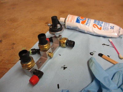
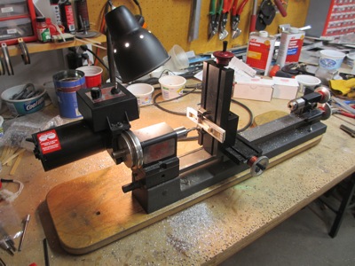
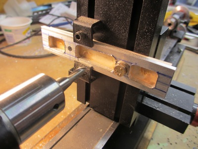
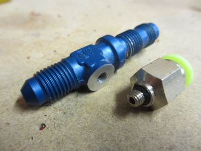
I chose to tackle both at once by modifying the bulkhead tee fitting that I previously installed through the firewall. I cut off the right angle leg, filed it flat (this was before I had a milling machine, or else I'd have used that) and tapped the hole for 10-32 threads. Then I installed a similarly threaded quick connect air fitting using Permatex #2.

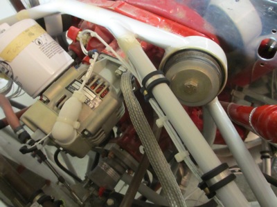
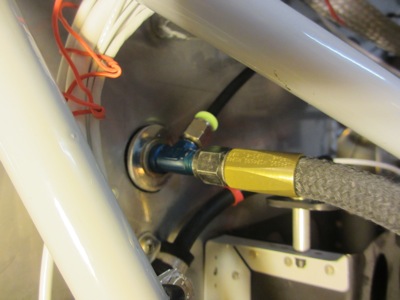
Here's the modified air fitting re-installed in the firewall. The aft side, not shown here, is blocked off with an AN929 cap. This effectively turns the former tee fitting into a firewall-mounted right-angle hose-to-tube adapter.

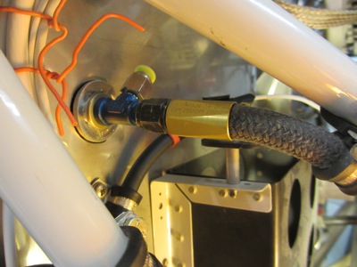
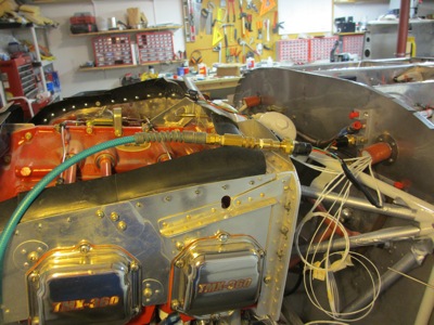
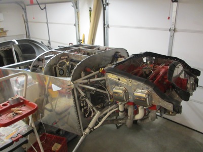
This is a wider shot of the area in question. Manifold pressure is conveyed from a port on the back on the #3 cylinder to the fitting/adapter on the firewall via a hose, which is strain-relieved via an adel clamp attached to the engine mount. This originally had two attach points; I may hook the other one up again someday if it appears necessary.

From the firewall connection, the manifold pressure hookup transitions to 1/4" nylon tube, seen here as a black stripe because the camera wouldn't focus where I wanted it.

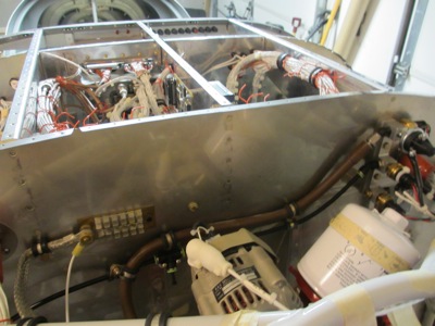
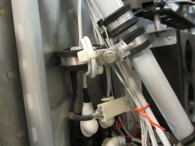
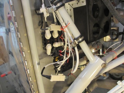
I attached a quick-connect tee fitting to the firewall using a simple aluminum tab affixed to an existing bolt hole. The middle leg of this fitting will eventually connect to the manifold pressure input on my ignition system (more on that in a future update) but for now it's just plugged. A pair of adel clamps keeps the manifold pressure tube from rubbing on the oil pressure hose and vice versa.

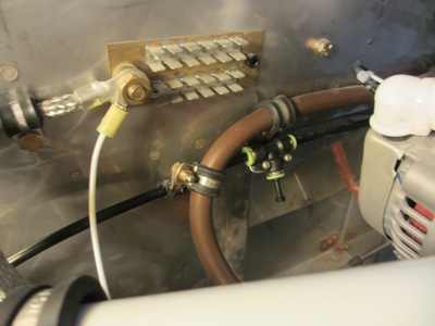
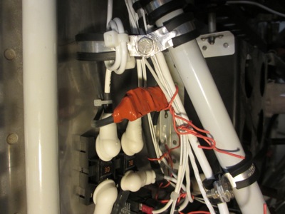
Here you can vaguely see the entire route of the black plastic manifold pressure line, from the hose transition on the starboard side, across the firewall through a tee to the sensor manifold on the pilot's side. In retrospect it's not exactly how I might have chosen to hook it up had I known I wouldn't need to bring it through the firewall, but it's not a bad arrangement regardless.

Engine pressure sensors

Sunday, September 2nd, 2012

The electronic transducers that sense engine oil pressure, fuel pressure, and manifold pressure are all mounted on a manifold on the left side of the firewall. I ran the wiring to all three, then used some brass air fittings and the compressor to test the oil and fuel pressure sensors. Manifold pressure is easier to test since you can just compare the readout to ambient air pressure.

I used Permatex #2 to seal the sensors, plugs, and fittings as I screwed them into the manifold. The oil pressure sensor is hung off the side of the manifold, since the oil pressure switch (which drives the Hobbs meter and the low oil pressure warning light) is much too big to be placed anywhere else other than cantilevered straight out from the firewall. In fact, I discovered to my chagrin that the oil pressure sensor doesn't quite fit either – the radius is too big by an eighth of an inch – but I have a plan for that…

In classic style, I used this little challenge as an opportunity to buy a new tool. Seen here is a vertical milling table attached my lathe, which turns it into a very small milling machine of sorts:

I cut a piece of 3/16" aluminum bar stock, match drilled it to the transducer manifold, and then bolted/clamped it to the new milling table and milled out some lightening holes:

It's not perfect, but it's not bad for my first real part made using a milling machine. It's quite light, since most of the material in the heavy bar of aluminum has been milled out.

Now the manifold can be spaced out from the firewall, allowing the oil pressure sensor to fit:

…just like this:

I secured all the sensor wiring with tie wraps. Later I'll connect the three wires for the oil pressure switch.

The milling conversion attachment for the lathe wasn't all that expensive, but I have a feeling that it is going to end up costing me a more in the long run. Now that I've successfully made a useful part on a mill – something I never thought I'd be able to do – I'm already having impure thoughts about upgrading to a larger and more capable machine. I wonder if Mary would notice if I put a Bridgeport in the guest bedroom?

Current sensor wiring

Saturday, September 1st, 2012

I hereby deem the cowl and baffles to be as finished as they're going to get, at least for right now. To celebrate I removed the forward top skin – which had become quite dusty! – in order to get caught up on some wiring tasks.

I connected and secured the standby alternator field wire and B-lead… note adel clamps and strain relief:

I had previously mounted the current sensor for the main alternator, but I never got around to wiring it or installing its twin that measures current from the standby alternator. The second sensor I installed with an adel clamp from the engine mount, right above the fuse holder where the standby alternator B-lead connects. Since these are 100-amp sensors and the standby alternator is only capable of 20 amps, I looped the wire through three times in order to achieve a little better resolution on the display. A calibration step in the G3X software allows you to apply a scale factor of 0.33 to account for this trick.

Here's a wider shot showing both current sensor hookups. To make them serviceable I used mini molex connectors, which are shown here prior to being secured in the wire bundles.

I wrapped the connectors with silicone tape in order to make them somewhat waterproof:

Then I powered up the avionics and calibrated both current measurements to zero. The machine is starting to wake up…