Archive for the ‘Trim Tab’ Category

Connected elevator trim

Saturday, May 20th, 2023

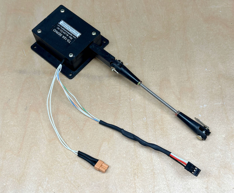
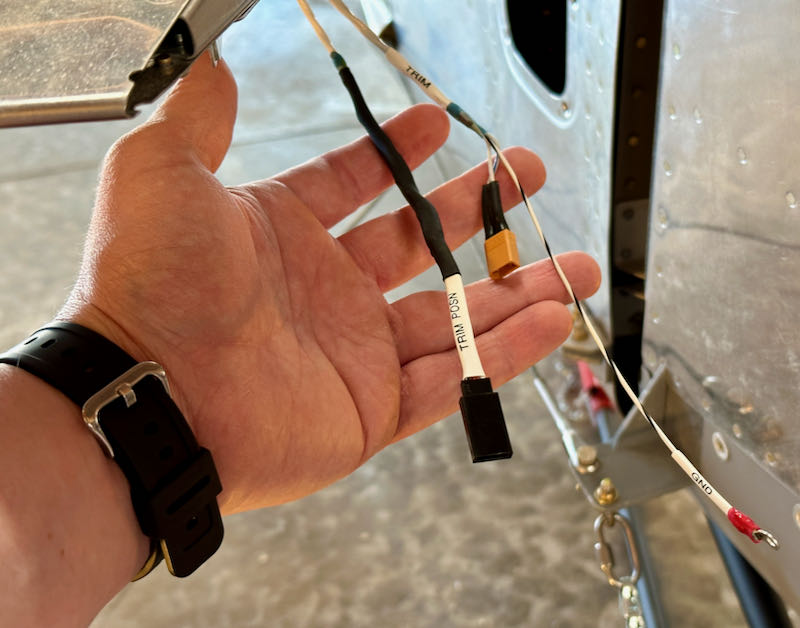
I pulled the elevator trim servo and associated parts out of storage so I could finish the pitch trim installation. The wiring here requires some kind of connector so you can remove the servo and/or the entire elevator, and furthermore whatever connector you use has to be able to pass through the 7/16" ID bushing in the elevator spar. Taking a page from RC aircraft, I decided to use a model airplane servo connector for the trim position wires, and an XT30 power connector for the servo motor itself. These I soldered to the wire pigtail and secured with heatshrink:

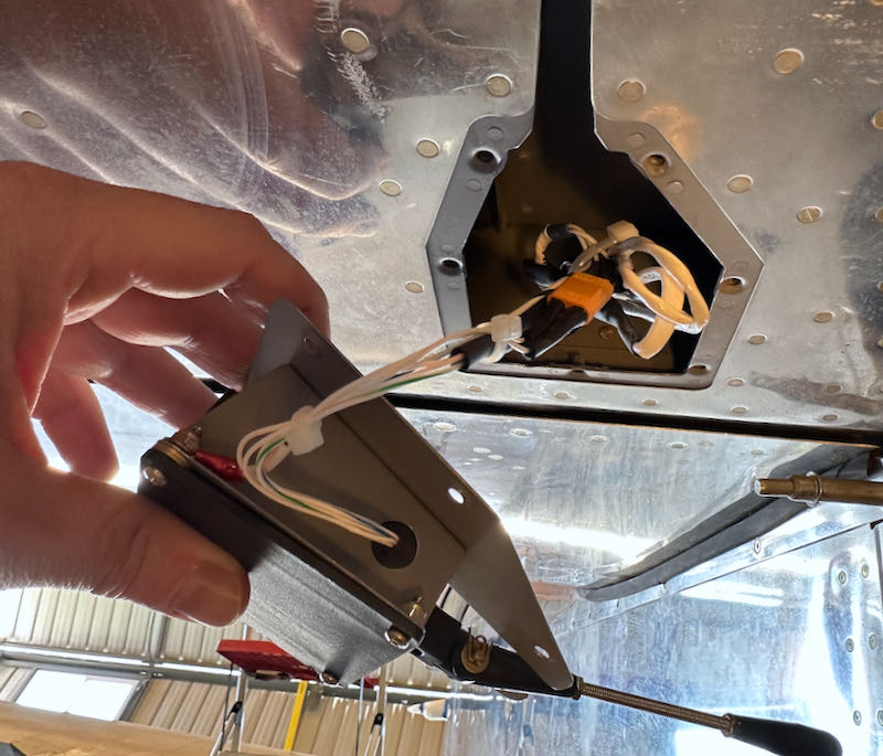
The above job was pretty easy since I was able to do it on my spacious, well-lit workbench using my good soldering station. By contrast, the mating connectors on the airplane were more of a pain since I had to use my crappy old Radio Shack portable iron while laying awkwardly on the ground under the tail. If I was smarter I would have done this when I was originally fabricating the wiring harness for the tail, but I clearly wasn't thinking far enough ahead.

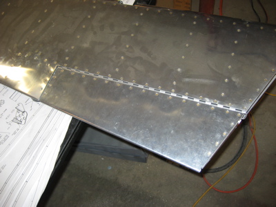
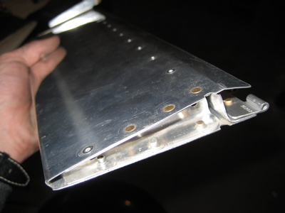
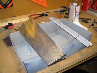
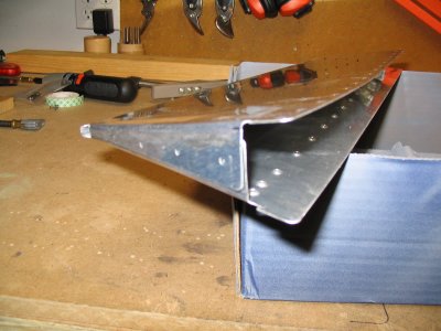
After testing to make sure it was correct, I bundled up all this wiring and stuffed it into the elevator along with the trim servo. The power wires are shielded in accordance with the G3X manual, and the shield is grounded to the airframe using one of the servo mounting screws:

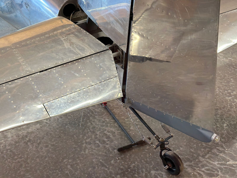
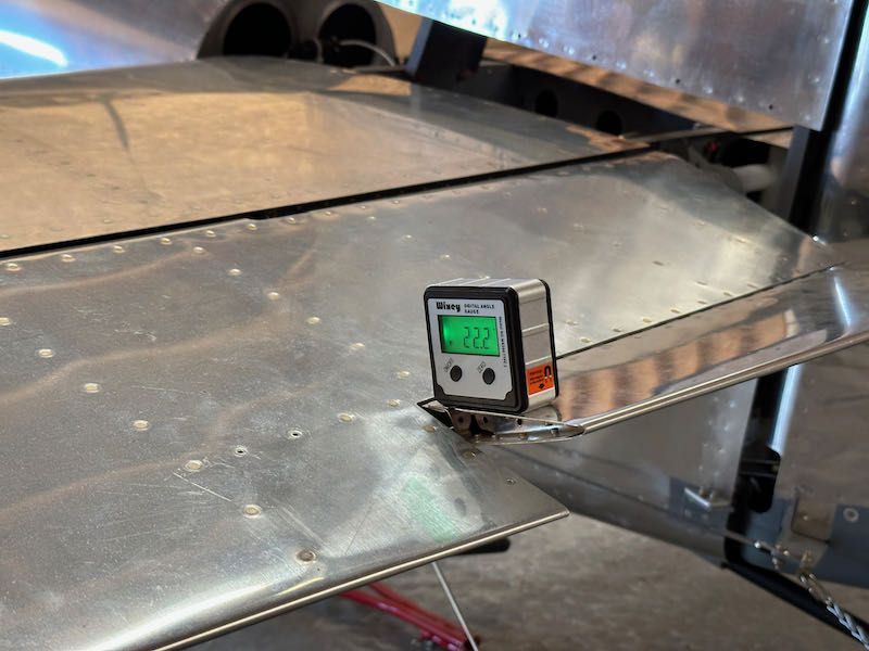
I don't have the cockpit trim controls installed yet, but I am able to run the trim by selectively grounding the individual loose wires that will eventually go to the stick grip switches. I did some minor fiddling with the trim linkage until I had roughly equal travel up and down, a little over 22° each way. The plans say this should be "25-35 degrees maximum", which isn't particularly clear or helpful. If I need more or less trim at some point down the road, I can always come back and adjust this.

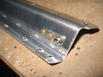
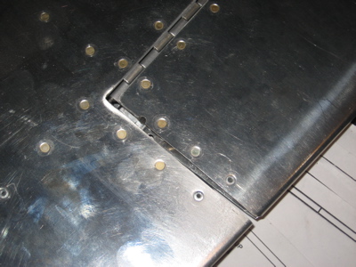
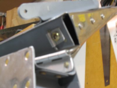
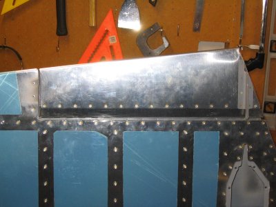
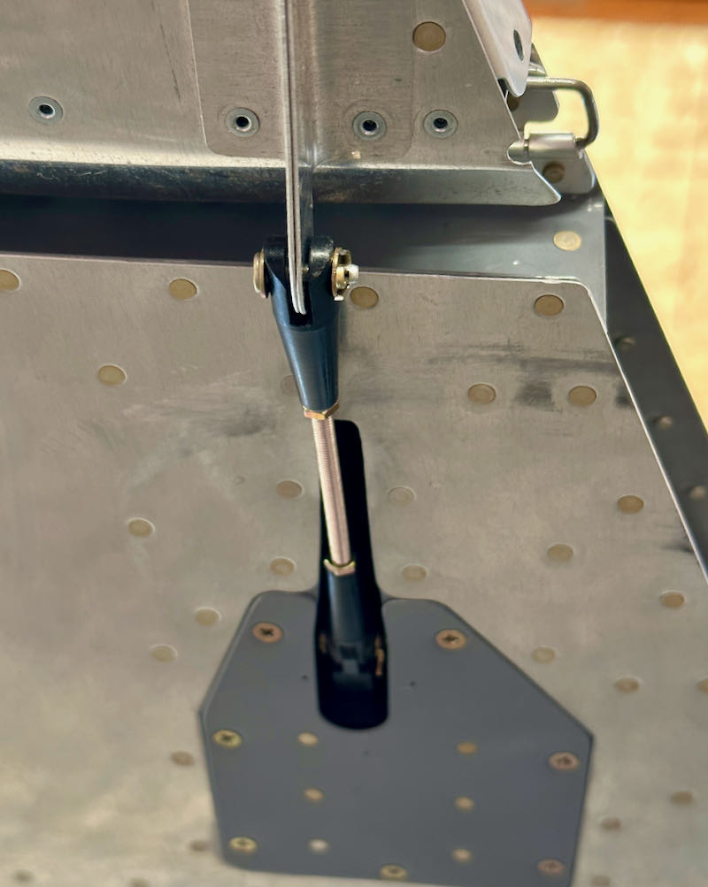
I installed the clevis and cotter pin, so the elevator trim is properly connected now in all senses:

I did a quick calibration of the G3X elevator trim gauge, and happily everything seems to be working electrically:

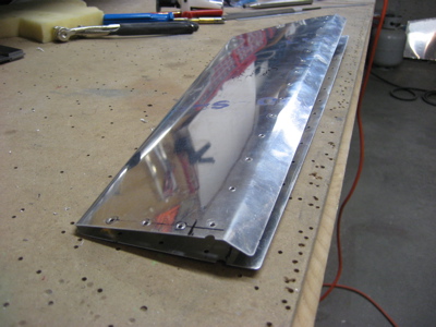
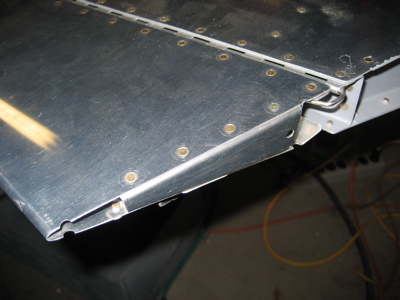
So that's one more flight control surface finished, a small but satisfying milestone:

Yet another trim tab

Sunday, February 25th, 2007

So here's the deal.. I decided to build a new trim tab today. The reasons were many:

1. I was fed up with fiberglass and wanted to make something out of metal.
2. I had the left elevator out already.
3. I was already in posession of the necessary parts, having ordered them a while ago (see #4).
4. John brought his trim tab to work to show it off, and it was so much better than the other one I'd previously made that I was shamed into building a replacement in order to redeem myself.

Absolutely the first thing I did was cut off the little flaps on each end of the skin. This trim tab ain't gonna have no bent flaps, it'll have ribs like a real aircraft control surface.

To make the inboard rib, I simply took an extra E-709 rib I'd bought from Van's and cut off the back end.

Here the inboard rib after being shaped to fit and clecoed in place. I decided to make the flanges point outboard, even though it made riveting harder – having the flanges point inboard would have put the web in a position to interfere with the rivets holding the control horns to the skin.

The inboard rib has a couple of strategic divots to clear some of those previously mentioned control horn rivets.

To make the outboard rib, I first cut a block of wood to the correct shape. I then took a piece of 0.025" alclad, started the bends with my hand seamer, and clecoed it to the form block.

Using a flush set and with my rivet gun turned down low, I finished the bends by hammering the aluminum down onto the form block. This is, of course, the same technique that the plans have you use to fold the tabs on the end of the trim tab skin, but doing it this way is a lot easier and more precise. Plus, if you screw up you just throw it away and grab another piece of alclad.

Here's the outboard rib after being fitted and clecoed in place. Notice I staggered the rivet holes at the aft end for clearance.

I fitted the hinge to the elevator in the usual way:

Then, after deburring but before dimpling, I formed the bend in the lower skin. The plans have you do this after the entire trim tab is riveted together, but if you do it before the spar is in the way you can make a slightly nicer bend. However this gives you less clearance for riveting the hinge, so you have to think carefully about the order in which you rivet the various things together.

I put a nutplate on the trim tab spar to capture the hinge pin, the same way I did last time around.

Here's the finished product, all riveted together and ready to go:

And, installed in its home on the elevator:

The gap between the trim tab and elevator is nice and uniform. You can see that I had to use one blind rivet at the aft end of the smaller outboard rib – this is the only pop rivet on the (more visible) top surface of the new trim tab.

Here's the underside of the outboard rib – I used one pop rivet at the aft end here too.

On the inboard side, I was able to use all solid rivets on top.

On the bottom, I used all solid rivets except for along the spar – there I was forced to use a row MK-319's to close everything up. I think if I had to do it over again (oh no!) I could probably find a way to turn the inboard rib the other way 'round and build the whole trim tab using only two pop rivets, but oh well. Come to think of it, that could be a good game show: "I can build that trim tab with two pop rivets!" – I'd watch. Anyway, lots of builders use blind rivets on the bottom just like I did, and it's approved by Van's. Good enough.

And finally – celebration.

Finished trim tab

Saturday, October 1st, 2005

I managed to use all solid rivets on the bottom of the trim tab, except for one blind rivet each at the aft ends of the E-717 and E-718 control horn halves. It would have been perfectly okay to use blind rivets all the way across, and plenty of people have done it that way, but I am feeling triumphant today because I succeeded in finding a way to squeeze all the spar rivets and almost all the control horn rivets.

Here the forward half of the trim tab hinge has been drilled, after lining up the trim tab carefully with the elevator:

Here's how I secured the end of the hinge pin – a hinge eye affixed to the trim tab spar via a nutplate. Can't take credit for this neat idea since I read it somewhere else first.

Here's the finished trim tab, completely installed. Look at those solid rivets in the spar… mmm, solid rivets…

Trim tab work

Wednesday, September 28th, 2005

After a couple nights of trying, I finally got a good bend on both ends of the trim tab. I'm just glad I'm not the only RV builder to go through a couple of trim tab skins before the bends turn out right. I ended up going with the bent skin flaps as shown in the plans, rather than the little-ribs idea, because I figured the inboard rib would interfere with the E-717/718 horn assembly.

Now to wait for the primer to dry before I rivet it all together and fit it to the elevator – and after than, the tail kit will almost done! It's been slow going lately, but that's okay because the fuselage and wing kits won't arrive until next month anyway.