Archive for April, 2006

Autopilot work

Sunday, April 2nd, 2006

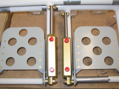
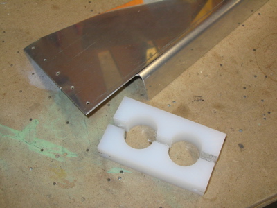
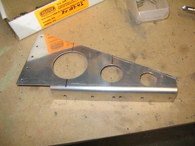
I broke out the TruTrak pitch servo today. Here's a shot of the servo and its bracket, next to the skimpy instruction sheet.

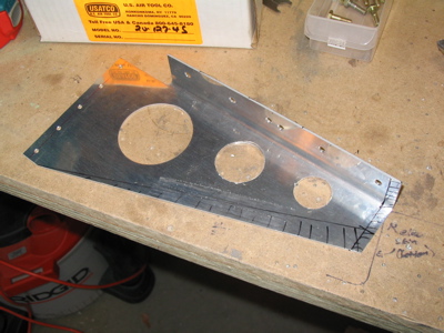
I drilled out four of the rivets in the F-729 bellcrank rib, then back drilled the bracket in place. Once the position was fixed, I marked and drilled three more #30 holes in the upright part of the bracket and four #40 holes through the bottom flange and belly skin. The holes in the skin were dimpled using pop rivet dimple dies.

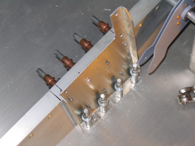
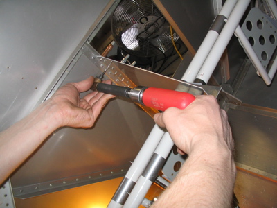
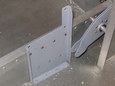
After priming the bracket, I riveted it in place. Four solid rivets to replace the ones I drilled out, three pop rivets below where the squeezer couldn't reach (i.e. I didn't feel like shooting and bucking while leaning into the tailcone). Then Mary helped me back rivet the four rivets through the bottom flange (because she is awesome). The bracket is very secure and sure as heck isn't going anywhere.

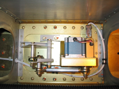
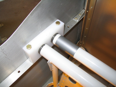
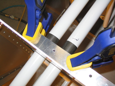
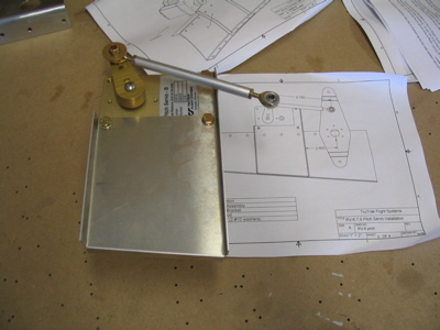
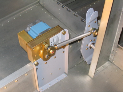
Here's the servo temporarily installed, to test how the linkage works. It looks like it will be fine. Even with a stack of washers for spacing, the short pushrod isn't completely straight, but apparently that's normal.

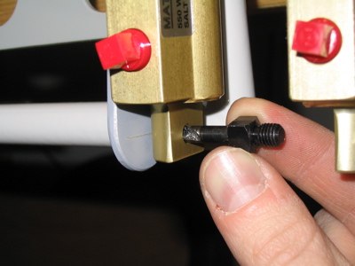
While I was messing around with autopilot stuff, I removed the roll servo from the wing, tightened the screws that keep the DB9 connector in place, and put everything back in. This would have been easier to do all at once the first time, but of course I wasn't thinking about the wiring when I installed the servo. I played around with some cool slide-lock connectors that I bought from Digi-Key, thinking that I'd be able to use them instead of screws, but they didn't fit. Oh well, there probably won't ever be a need to remove that connector, and if I really have to I can just pull the servo out again through the access hole.

Rudder pedal installation

Saturday, April 1st, 2006

Here are the rudder pedals, with all the different pieces either primed or powder coated and riveted together.

I clamped some lumber to the bench so I could hang the pedal weldments in their natural state. Here I've temporarily bolted in one set of pedals and brake master cylinders. You can see that when the pedals themselves are lined up, the vertical parts of the weldments are not parallel, because of the way they're mounted.

One of my weldments seems to have been made a little crooked. When the pilot's pedals are lined up, the copilot's pedals are off by about 1/2". I figure this is not worth worrying about – I'll just build it so the pilot's pedals are straight, and the copilot will be the one who has to deal.

I stole Checkoway's method for marking the location to drill the hole for the bolt that attaches the brake master cylinders to the pedals. With everything aligned and clamped in place, I used a short drill bit to scribe a reference line. Then I took everything apart to drill and deburr the holes. Doing it that way was a lot easier than trying to drill everything in place.

Here's a bottom view of how the brake cylinders attach to the pedals. The plans show a stack of four washers and tell you to use however many are necessary to make the cylinders line up. Four seemed to work out just fine for me.

Another view:

Here's one of the side bearing blocks in which the rudder pedal tubes pivot. You can see I've already drilled three sets of mounting holes (the forwardmost and rearmost positions share a central hole in common). This is to allow customization of the seat-to-pedals distance, but if my experience with the RV-9A is any guide I'll probably just bolt them in the forwardmost position and leave them there for all time. I used the angle drill with a longish #12 bit to make these holes.

I trimmed a chunk out of the center rudder pedal brace in order to clear the firewall recess, and drilled the holes that will mount it to a firewall stiffener. I also drilled the bolt holes in the center bearing block and then split it lengthwise so it can be installed. My bandsaw with the metal cutting blade didn't like cutting the UHMW very much, but a regular crosscut wood saw went right through it.

I match drilled the pilot holes I previously drilled in the center brace into the firewall stiffener with the angle drill. You could probably build a whole airplane without one of these, but I wouldn't want to try.

Drilling the center bearing block to the brace involved a lot of fitting, clamping, and removing the assembly from the airplane in order to drill from the back side. This might have been easier with a slow build kit but it turned out okay.

I put some lightening holes in the brace and marked some areas for trimming. You can also see from the hole pattern that the hole spacing on the center bearing block is different than on the side blocks, so the center hole can't be reused. I wonder why they did it that way? Oh well, at least I didn't have any edge distance problems with any of these holes.

Here's the final version of the center brace after being trimmed and filed.

The rudder pedals are now ready to mount in the airplane, except first I need to put cotter pins in all the castle nuts. I also need to order some shorter drilled-shank bolts to use in a couple places where the plans called out a bolt that was way too long.