On Saturday I tripped going down the stairs with a big basket of laundry and wrenched my ankle rather smartly, so between icing down my swollen ankle and studying for the commercial written exam I didn't get a lot accomplished on the airplane this weekend.
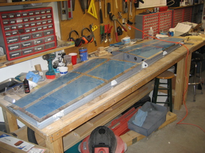
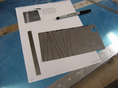
I did however manage to get one little task mostly done, which was fabricating and installing the rudder cable exit fairings. The plans just have you punch the rudder cable fairings straight through the fuselage side, and there's probably nothing wrong with that, but it does seem like a small set of fairings would help to aerodynamically clean up that area. You can get pre-made fairings, but I wanted to do it the hard way and make them myself. So, first I drew a whole bunch of lines on a piece of 0.020" alclad scrap, using the dimensions given by Sam Buchanan as a starting point.
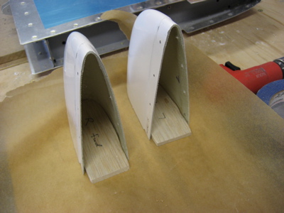
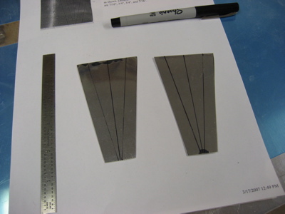
Then the two pieces were cut out:
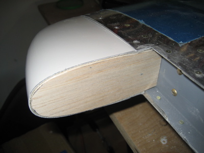
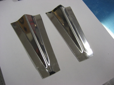
A little work with the hand seamer, and I had a nice looking pair of fairings. All for the low low price of free.
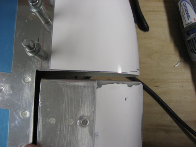
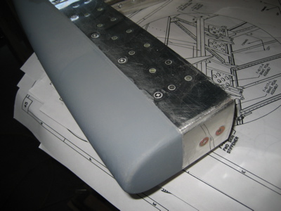
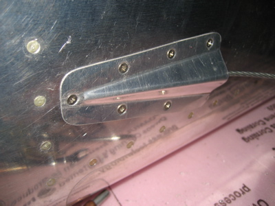
I laid out holes along the flanges and drilled the fairings to the fuselage. They are aligned with the main longerons, which are level in cruise flight. Notice there are three holes on top and only two on the bottom – that's because the lower fuselage stiffener is in the way of where I would have put the third lower hole. Actually I did drill a hole in that location, which you can see in one of the other photos below, but it's too close to the stiffener to dimple so I just covered it up with the undrilled fairing.

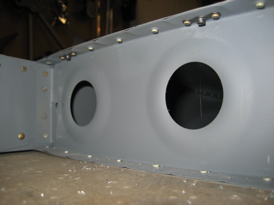
I had several choices for how to attach the fairings to the fuselage. In order of increasing difficulty, they were: A) round-head pop rivets; B) flush pop rivets; C) flush screws and nutplates. If you've been reading this site for long you've already guessed that I picked option C. However, it wasn't just as simple as riveting nutplates to the fuselage skin, because it was too tight inside the already-riveted tailcone to have any kind of decent bucking access. So, after some head scratching and trial and error, I made a nut ring to support the nutplates on the back side of the skin. The odd shape lets it clear the cable slot and the various other structural elements back there.
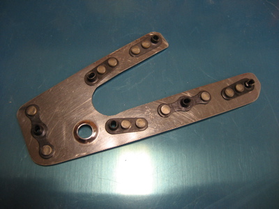
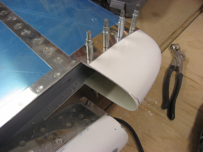
The same screw that attaches the adel clamp to the fuselage side also holds the nut ring in position. The fairing and fuselage skin are dimpled, and the nut ring is countersunk to accept the skin dimples.
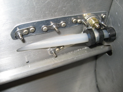
On the exterior side, flush stainless 4-40 screws hold the fairing to the skin. Since it's removable I was able to iteratively shape the edges with my hand seamer until the whole thing laid down tight against the skin with no gaps anywhere. Now I have custom, scratch-built rudder cable fairings that continue the cool attached-with-screws motif that I have going on with the other empennage parts. Hopefully at least one person at a fly-in somewhere will look under the stabilizer and go "woah, how'd he do that?". Plus if I ever need to replace the rudder cables I won't have to drill out any rivets and mess up my paint.
I still need to finish installing the other fairing, but now that I have a template to make the nut ring it should be no sweat.