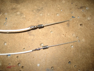
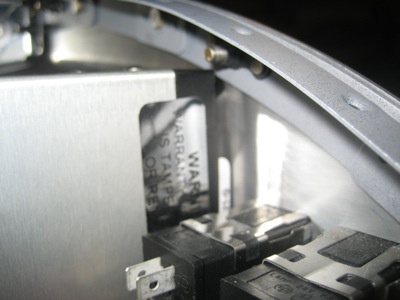
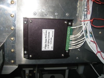
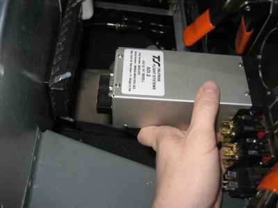
I can't afford a real two-inch standby attitude gyro (they cost a mint… and I'm talking this kind of mint, not this one) so I have a TruTrak ADI instead. It's not a real attitude indicator, but it should be good enough for a backup instrument. And since it's a safety-of-flight item, I wanted to make sure it was fed by dual power paths, as are the other most important avionics in my panel. Unfortunately TruTrak didn't provide dual diode-isolated power inputs like Garmin did, so I had to use a pair of 1N4001s to create my own:
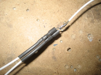
Heatshrink tubing protects against shorts – after I took this photo I added another piece, then crammed the whole assembly into the D-sub backshell. One side is fed by Bus 2, which powers my important avionics, and the other side is fed by the standby battery. This arrangement will also keep the gyro alive while cranking the engine, which might be a good thing considering some of the funny behavior Matthew reported when he had his ADI powered on while starting.
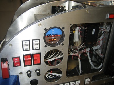
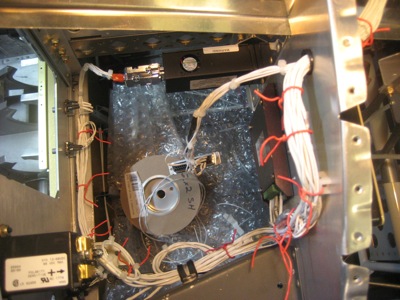
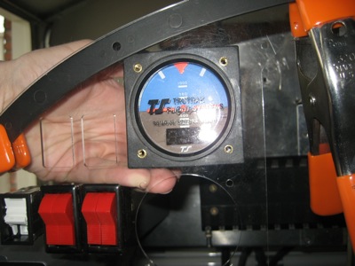
Here it is mounted in the panel… I verified that it powers on, figures out which way is up, and receives GPS data.
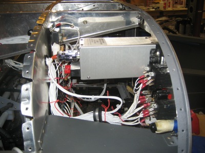
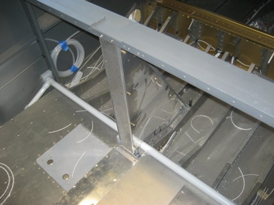
Port-side view of the ADI wiring harness. The D-sub connector comes pretty close to the panel, but there's enough room to avoid kinking any wires. However, it would not have fit if I'd mounted it in the center standby instrument hole as I'd planned, which is why I moved it to the top.
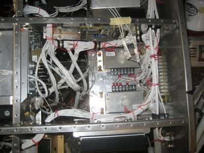
"But I thought the ADI wouldn't fit in the top hole!" you say, or at least that's what you might say if I allowed comments on this blog, which thanks to the efforts of spammers I don't, thank you very much spammers. "You even posted a photo of this exact thing!" you might also exclaim if I let you. Well, yes, but that was before I figured out that a UMA light bezel inserted ahead of the instrument spaces it back far enough to clear the panel frame:
So thanks to the light bezel the ADI now lives at the top of the stack of standby instruments.
This is actually great news, because I was already planning to use UMA light bezels for my standby altimeter and airspeed indicator, and I was bothered by the fact that the ADI's internal lighting didn't match them in color or intensity. So, I broke out my Fluke and did some probing around… It turns out that I was able to defeat the ADI's internal lighting by connecting the 5V output pin on the dimmer unit to the ADI pin that's designed to be connected to a 24V lighting bus. What happens is that when I turn on the nav light switch, thus energizing the dimmer, the ADI sees five volts on its 24V lighting input (equivalent to 2.5V with a 12V lighting bus) and reduces the brightness of its orange LED display… but 5V isn't high enough to turn on its internal lighting, so I'm free to use my light bezel to light the instrument face instead. The dimmer potentiometers don't care about the extra milliamp or two that the ADI sinks on its lighting input pin. Excellent.
If you're still awake after reading the above paragraph… yes, I can be a huge geek sometimes.