Author Archive

Installed prop governor

Wednesday, February 6th, 2008

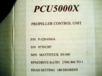
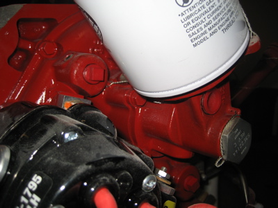
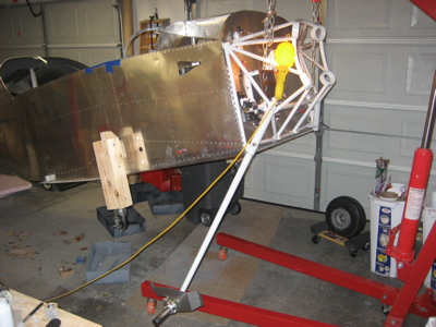
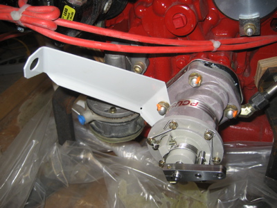
Here's the propeller governor, a PCU500X. This guy is basically an speed-controlled oil pump, which controls the pressure of the oil being pumped through the hollow crankshaft, and thus sets the pitch of the propeller blades to hold the desired RPM. I started to explain this to Mary but she was too distracted to endure another of my lectures about aviation theory, so I just told her "it costs a thousand dollars and makes the airplane go like hell."

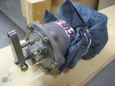
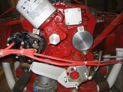
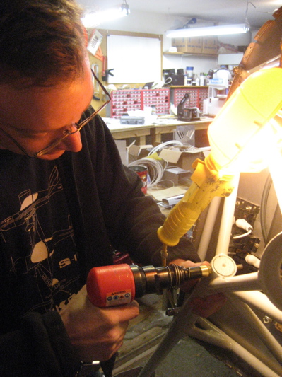
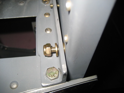
I had to cut off the safety wire, loosen the screws, and rotate the shaft to the correct angle to fit Van's cable bracket. Here it is after I redid the safety wire:

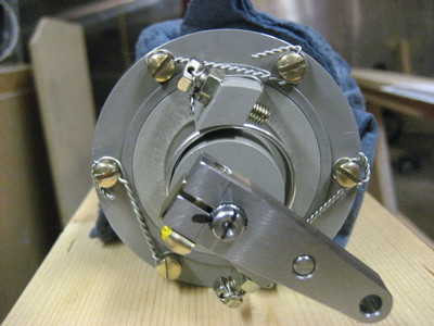
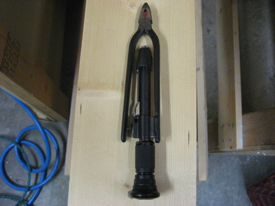
I used my cool new Milbar reversible safety wire pliers to twist the new lockwire, and I must say the improvement in my safety wire workmanship is noticeable compared to when I was using the old, cheap pliers. I guess once again I learn that quality tools make a difference.

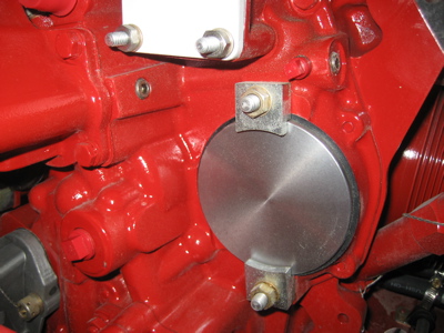
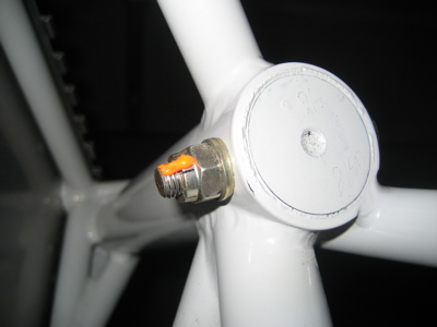
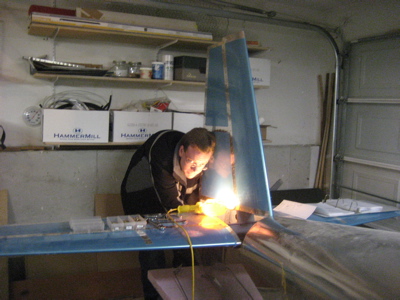
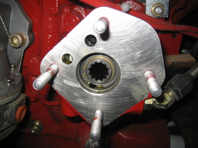
I wiped down the surface of the governor drive pad, and removed the caps covering the drive gear and the oil ports:

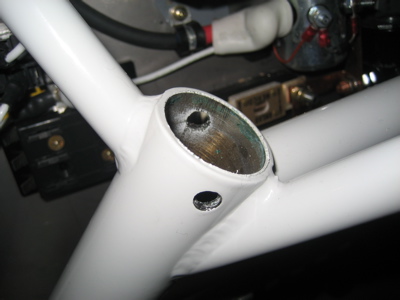
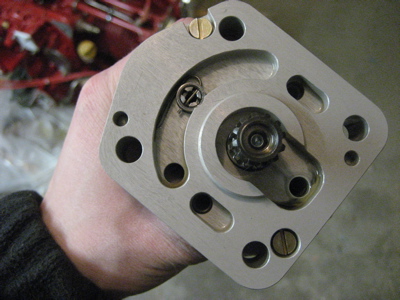
Likewise, I cleaned the mating surface on the governor and removed the plastic plugs from it too. I made sure to take these photos so I don't have to wonder, "did I really remember to remove those plugs before I bolted on the governor?"

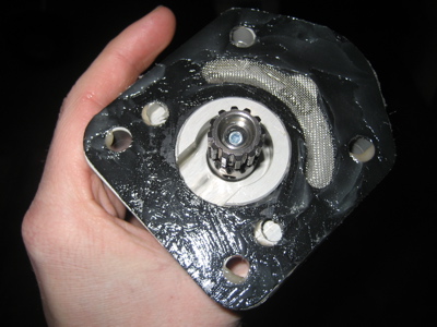
The instruction sheet that comes with the governor says to coat both sides of the included gasket with "a suitable release agent". I dithered on this for a while before finding an old RV-List posting mentioning that Van's preferred substance is plain old fuel lube. I guess the idea here is to make it possible to remove the old gasket if you have to remove the governor, and not to put something on there to enhance the quality of the seal (e.g. Permatex).

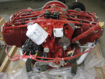
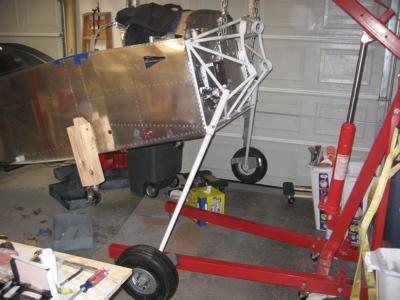
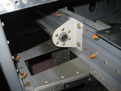
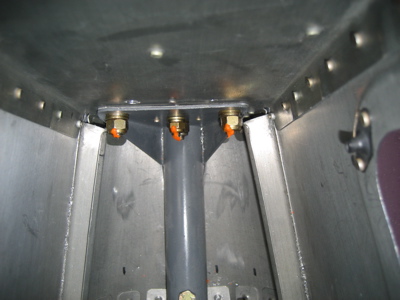
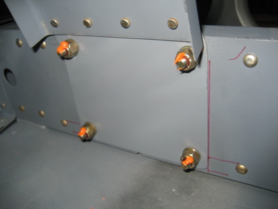
Then I bolted the governor and cable bracket to the engine, using star washers under the nuts. Due to the clearances involved I had to use a crow's foot on my torque wrench when tightening the nuts, but that was no big deal.

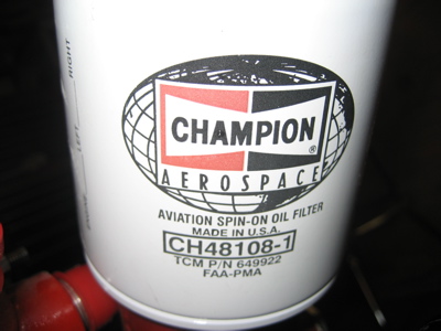
Here's the model info and serial number, in case I ever need it:

Engine stuff

Wednesday, February 6th, 2008

Still waiting on one last box of parts to arrive before this weekend's building session, but in the meantime I spent some time getting familiar with the engine and planning what I need to do before I bolt it to the airplane.

Here's a view of the accessory case on the back of the engine. Clockwise from the left we have the left magneto (black thing with red wires coming out of it), oil filter, vacuum pump drive pad, right magneto drive pad (unused, covered with a circular plate), prop governor drive pad (with cable bracket in place for a test fit), and engine-driven fuel pump (silver thing with blue fitting cap). The hexagonal silver thing in the approximate center of the accessory case is the vernatherm valve (basically an oil thermostat). Above and to the left of the vernatherm is the oil temperature transducer port, directly above is the tach drive pad, and below and to the right is the supply port to the oil cooler.

Closeup view of the right side of the accessory case, showing the vacuum pump and magneto drive pads, and the supply port to the oil cooler. Also visible is the port for the oil pressure gauge – it's the small hole with a red plug threaded into it, just above the magneto drive pad. (Sorry, all my pipe plugs are the same color as the engine itself, which makes them not photograph well)

Closeup view of the left side, looking past the magneto. Here you can see the return port from the oil cooler, which hides behind the oil filter. In fact I'll probably have to remove the filter to get a fitting on there.

Since this engine has a right-angle oil filter adapter, it uses a CH48108-1 filter, which has a built-in check valve. That should help keep oil changes from becoming a major environmental hazard, which has not always been the case with other airplanes I've owned. These filters are also about ninteen bucks each, but that's aviation for you.

Gearleg nuts

Tuesday, February 5th, 2008

In this week's Aircraft Spruce shipment I received the proper nuts to go on the bolts that secure the gearlegs to the engine mount, so on they went:

The plans call for regular AN365 nyloc nuts here, but I've already decided to use only all-metal locknuts forward of the firewall, no exceptions. AC43.13 only forbids nylon nuts where temperatures exceed 250°F, but since I'm not in a position to measure peak temperatures in various locations forward of the firewall, I'd rather just outlaw nylocs entirely.

Rolling on the gear

Saturday, January 26th, 2008

I reamed the bolt holes in the engine mount's gearleg sockets to 0.311", which is a few thousandths undersize for a 5/16" bolt. The goal is to have a zero-slop press fit for the bolts that go here, to keep them from elongating their holes as the gear absorbs loads during use.

I set up Scott's hoist and attached it to the fuselage, using sections of clear vinyl hose material slipped over the engine mount tubes to keep them from getting crunched up by the chains.

"Not to be used for aircraft purposes" – hmm.

Having one end of the the fuselage suspended several feet in the air and the other end supported by a single little wheel induced a certain degree of nervousness.

I had to grind off some of the excess powder coating on the gearlegs to get them to go all the way into their sockets. I also ground a very slight chamfer at the top to keep the rod from getting hung up inside the socket.

Since Mary had other things to do, I had to call and beg Scott to come help me steady the fuselage while I persuaded the gearlegs into the engine mount. The first one went in relatively easily, but the second one was a real pain, especially the last half-inch or so.

I used a low pressure in the rivet gun and a brass-tipped rivet set to drive the bolts home. This worked very well and seems to have resulted in some nice tight-fitting bolts. I need to pick up some AN363-524 metal locknuts, but in the meantime these bolts aren't in danger of going anywhere.

With both gearlegs installed, I put the wheels on the axles so the plane would have something to sit on when lowered to the ground:

The fuselage is on the gear! Suddenly, the airplane is much taller.

Big milestone today. Also, big thanks to Scott for his assistance and the use of his hoist. Don't tell China that I used it to lift an airplane, or they might come take it away.

Installed empennage for good

Saturday, January 26th, 2008

The tailwheel mount shares several bolts with the vertical stabilizer spar, so before you can put any substantial weight on the back wheel you have to install the vertical fin first. I've had the tail propped up on a pile of styrofoam insulation for a long time, but now it's time to get this thing standing on its own feet, or wheels as the case may be.

To provide the proper amount of vertical stabilizer offset, there is a single AN960-10 washer between the spar and the up-elevator stop, on the left side bolt only. This photo confirms that I did remember to install that pesky washer:

I torqued and marked all the bolts that attach the horizontal and vertical stabilizers:

I couldn't get a socket onto some of these, so I just tightened them using a wrench and German torque.

More bolts:

I couldn't get enough access to the nuts on these bolts to apply the orange torque seal goop, so I just marked the bolt heads to remind myself that I did actually torque the bolts.

The horizontal and vertical stabilizers are now mounted permanently, and the tailwheel is capable of supporting real weight. You can't really tell from this photo, but the tail is now resting on the tailwheel instead of sitting on a pile of foam.