Archive for the ‘Engine’ Category

Alternate air cable

Monday, November 4th, 2013

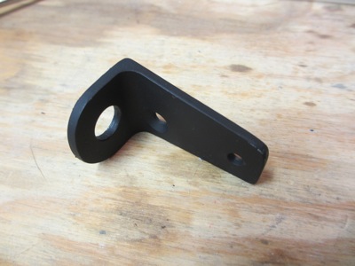
Returning to the alternate air door, which needs a control so the pilot can open it if required. It all starts with a bracket, made of 1/8" aluminum and designed to fit in a very specific place:

That place is the side of the throttle quadrant, attached using two of the existing mounting bolts:

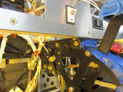
Locking push-pull cable housing installed in the bracket:

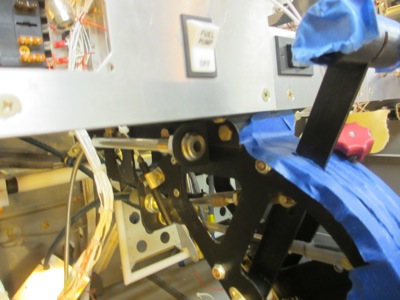
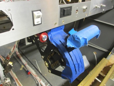
Here's what the cable knob looks like when it's in the "closed" (normal) position. I arranged things so the face is flush with the panel when it's not in use.

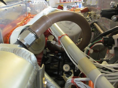
Marking and drilling the firewall for another cable passthrough fitting… this took some figuring in order to find the ideal routing:

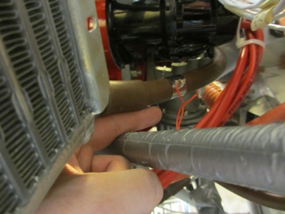
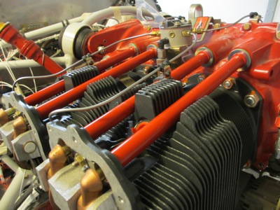
Just enough clearance between the engine mount tubes to cut, drill, and deburr. Duct tape is there to protect the engine mount from tool-induced scratches:

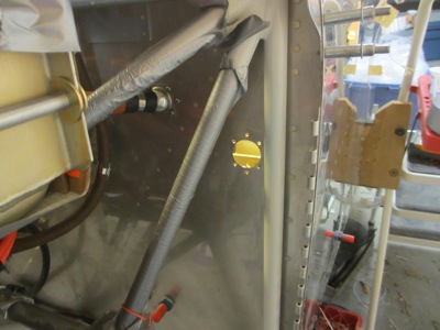
Eyeball fitting installed and cable sleeve in place:

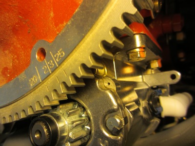
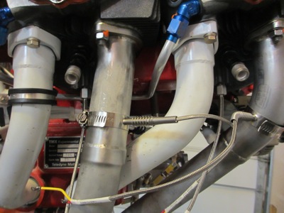
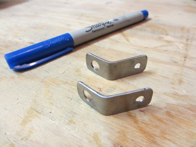
More custom-made brackets, this time from 4130 steel:

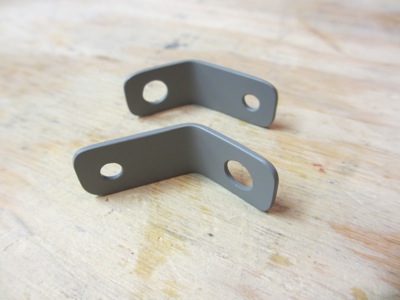
Primed and painted, with the paint baked on for durability (don't tell Mary I used her oven for airplane parts again).

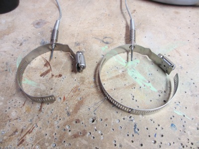
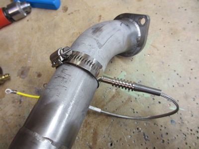
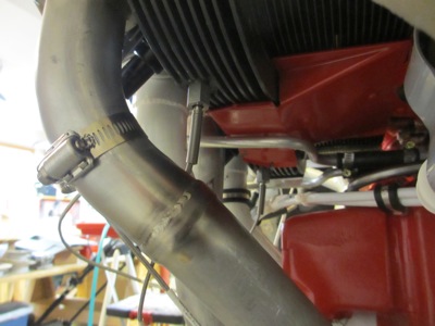
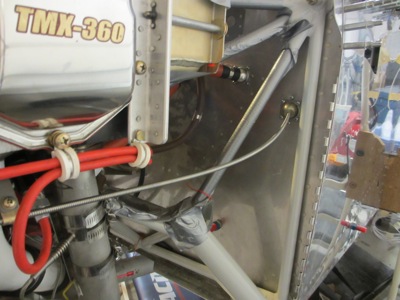
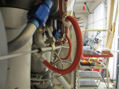
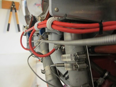
These brackets attach to the engine using a couple of bolts on the intake tubes, and support a pair of clamps around the cable sleeve:

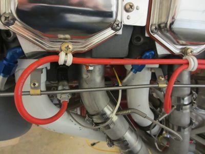
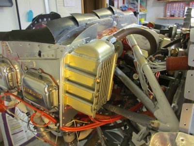
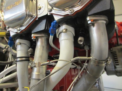
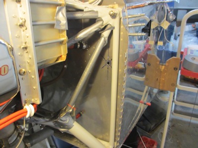
This routing is much simpler than the oddball idea shown in the plans, which I think would probably have conflicted with the mounting of the oil cooler anyway. Here the cable is just a straight shot to the front of the engine, with some slack at the aft end for when the engine moves around:

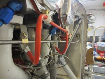
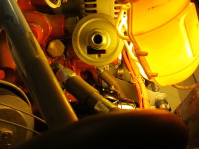
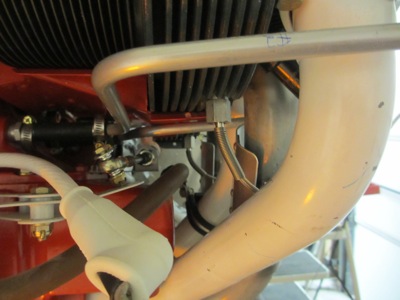
Here you can see that the cable runs well inside the loops formed in the ignition wire harness, and has plenty of clearance:

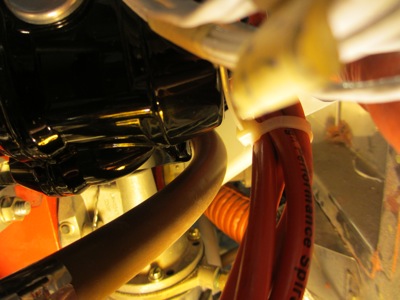
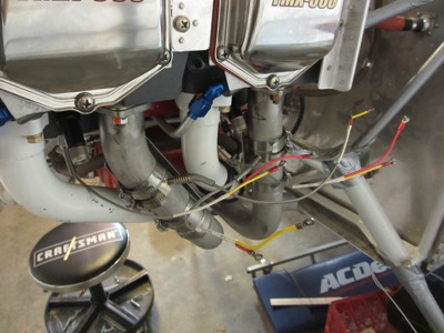
No problems at the aft end either, thanks to careful positioning of the firewall fitting:

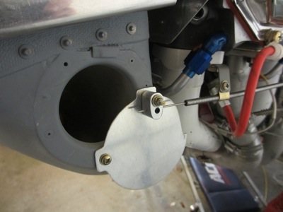
Next, we need a way to attach the cable to the door itself, so it will open when you pull on it. The plans suggest heating the cable with a torch and bending it around a screw. That seemed pretty lame to me, so instead I fabricated this little aluminum block on my milling machine. You'll see in a minute how it works…

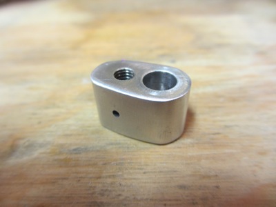
At the place on the door where the plans call for a simple screw and nut, with the cable hooked around it somehow, I instead fabricated a brass bushing that's captured securely between a pair of washers:

The bushing is just slightly longer than the width of the block, so the block can pivot freely on the bushing but is kept in place by the outer washer:

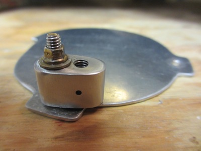
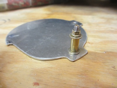
And now here's how the cable attaches to the block. The cable wire passes through the small hole, and is clamped between a pair of set screws which come in from either side. The principle is the same as the standard "cable B-nut", adapted to fit this application. Once I go to install everything for good, I'll use blue Loctite on the screws to keep them from backing out.

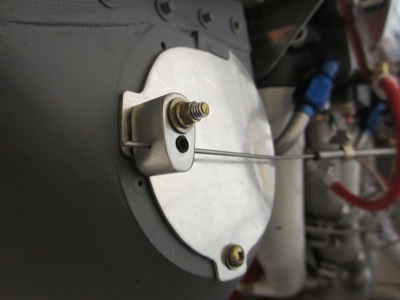
Alternate air door in the closed (normal) position:

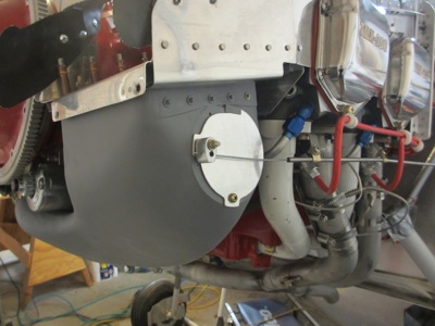
And here it is in the open (emergency) position:

When the door is open and the knob is fully extended, it looks like it might interfere with the throttle lever, but it doesn't. Luckily I thought of that before I went to all this trouble.

You can see from the above photos how it's unlikely you could close the door again, once opened, just by using the cable. The door doesn't want to slip under the little retaining tab at the top, hence why this is an emergency-only control that has to be reset via cowl removal once used. I don't particularly like that, since you can't test it before takeoff. I guess I'll put a "emergency use only" placard on it and hopefully never have to use it except at annual inspection time.

Update: See the next post for how I figured out how to work around this shortcoming.

Installed oil cooler

Monday, August 26th, 2013

Note to readers: Working on firewall forward tasks involves an endless series of chicken/egg scenarios. You often can't install item A until you fit item B, but you usually don't know how item B is going to fit until items A, C, Q, and X are all installed. So I'll try to break up the next series of posts into discrete topics, but be advised that the photos will show multiple projects happening at once, because that's how things actually transpired.

First up, final installation of the oil cooler. I was hoping to be able to keep putting this off, since it's big and fragile and in the way, but in order to install the left magneto I need the oil cooler in place so I can check the hose routing. Of course, in order to fit the oil cooler and hoses in the first place it would have been helpful to have the left magneto installed (see preceding paragraph).

I ended up having to re-clock the lower fitting in order to point the return hose slightly away from the magneto. Of course this meant I had to completely remove and re-seal it too. As for the upper fitting, I had to switch it from a 90 to a 45 to end up with a hose routing that wouldn't hit the mag.

You can sort of make out the magneto in there – it's the black thing just below the far end of the upper oil hose.

On the bottom side, it's a contest between the magneto and the engine mount to see which will interfere with the oil return hose the most. Since the cooler, hose, and magneto are all solidly mounted to the engine, they should in theory all move around together and not relative to one another. So, I chose to bias the hose as far away from the non-moving engine mount as possible – about one finger width, shown here – and accept the fact that the hose will come quite close to the mag.

Here you can see how close the hose comes to the magneto. Depending on the rotation of the mag when it's being timed, it could actually touch slightly. Once the mag is bolted down for good, I'll put some RTV in here to keep anything from chafing.

When you have the magneto in place, it becomes very hard to get a wrench on the inboard fitting of the return hose. In fact you can barely see it (middle of picture). I busted some knuckles getting it tight.

I guess in one sense I got lucky with my oil cooler plumbing – it was inconvenient to re-route the hoses, but at least I didn't have to have new ones made. At a hundred bucks a pop that would have been a bit more than an inconvenience.

Oil cooler mounting bolts, washers, and spacers all installed and torqued.

I sealed the gaps at the top and bottom and in the corners with more RTV. No sense letting any of that precious cooling air escape without doing useful work, i.e. flowing through the oil cooler.

Installed starter

Monday, August 26th, 2013

In order to set the magneto timing I'll need the ring gear and starter installed. I don't think I'll need access to anything else back behind there, so it's time to bolt the starter on for good:

Ring terminal tightened and bolts torqued, with lockwashers:

Flywheel and ring gear temporarily installed:

The flywheel has timing marks stamped on it, which you line up with that little hole on the starter in the center of the photo. Simpler than using a protractor or degree wheel.

EGT/CHT probes

Monday, May 27th, 2013

This photo shows the four exhaust riser pipes, each with a carefully-located and potentially very expensive hole drilled in it. Each one is 3.5" inches from the mounting flange, and oriented in a certain way that I determined after some tedious measurement and trial fitting:

Into each hole goes an exhaust gas temperature (EGT) probe, which is a clamp-on thermocouple that looks like this. I shortened the band clamps on each one to remove extra material I didn't need – these must be sized to fit some kind of monster exhaust pipes. (original version on the right, shortened version on the left)

The EGT probes clamp on to the exhaust pipes like so. I was skeptical that this would provide an adequately tight seal, but they are quite a tight fit into the reamed holes, and I don't think any exhaust blow-by will get past them.

Close-up detail of the safety wire on the clamps. They want you to tighten these to a surprisingly high torque – well beyond what you can do with just a screwdriver – and you definitely don't want them loosening up.

Exhaust reinstalled on engine, complete with temperature probes:

Meanwhile, another set of thermocouples is threaded into the underside of each cylinder, to allow the pilot to monitor cylinder head temperature (CHT). Here you can make out the CHT probes for cylinders 1 and 3:

Here are the CHT probes on the opposite side, for cylinders 2 and 4. (Pay no attention to the state of the mixture bellcrank in this photo, I finished re-hooking it up after I took this)

EGT and CHT probes installed on the starboard side, but not wired yet:

From this angle you can see why measuring the locations for the EGT probes was tedious… you have to make sure the sticking-out portion of each probe is tucked in enough that it doesn't get close to the cowl, but is pointed outboard enough to ensure that it doesn't interfere with anything else on the engine:

Probe wires in disarray on the port side of the engine. In time, I will bundle up all the thermocouple wires and extend them aft to the firewall. But before I can do that, I need to install the magneto and associated plug wiring. One thing at a time.

Installed new cylinders

Sunday, February 10th, 2013

After an unexpectedly long delay – due to schedule issues and also because ECI didn't send me all the expected parts on the first try – I finally managed to get my four new engine cylinders installed.

The cylinders are mounted and torqued, the pushrods and rocker arms are in, the oil drain tubes are back on, and the fuel injection lines are reinstalled and clamped. The intake and exhaust pipes are still off, since I want to get the EGT and CHT probes installed before I put them back on for good. And the rocker covers are not on yet because I ran out of steam and got tired of standing in the cold garage.

Grey cylinders with red pushrod tubes and crankcase is kind of a cool color scheme. Can't order 'em that way.

While I was complying with SB08-1, I also took care of SB12-1 by installing new stainless parts for the pushrod shroud tube retainer spring and lock tab.

Guiding me through this whole adventure was local engine guru Jerry Gippner, who taught me a lot about engine maintenance in the process. I think I could probably do it again on my own next time, so thanks Jerry for the education!

Next: Reinstalling baffles and other engine parts, hopefully for the last time (for the foreseeable future anyway).