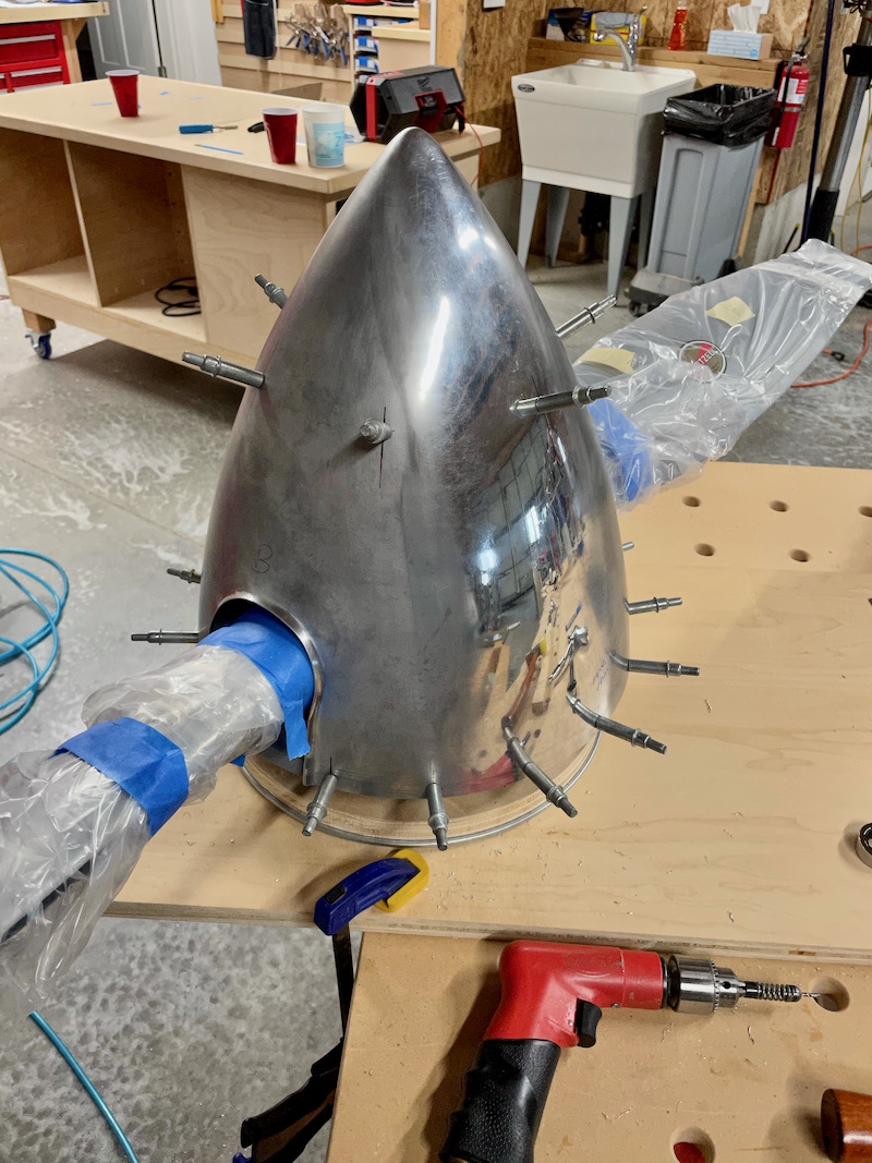
Most RV aircraft use the standard fiberglass spinner supplied with the kit, but because I'm congenitally unable to leave things well enough alone, I decided to buy an aluminum spinner from Cummins in Australia. It's a real work of metal-forming art, perfectly shaped, and even the blade cutouts are already made and flanged. I opted for the unpolished version, so I can have it polished or plated later after I'm all done fitting it to the propeller.
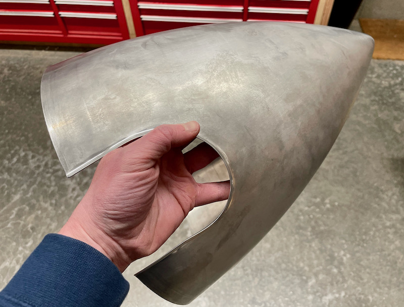
To avoid vibration and prevent the spinner from cracking due to stress, it's important to mount it to the propeller as accurately as possible. Ideally the spinner should run perfectly true with absolutely no wobble, i.e. zero runout. In practice, you just want to minimize the amount of runout by being as careful as possible with your measurements and drilling. I decided to shoot for ±0.030" or better, which is an ambitious goal. To do this, I devised what I think might be a novel approach to fitting the RV spinner, which should work equally well for most any aircraft project.
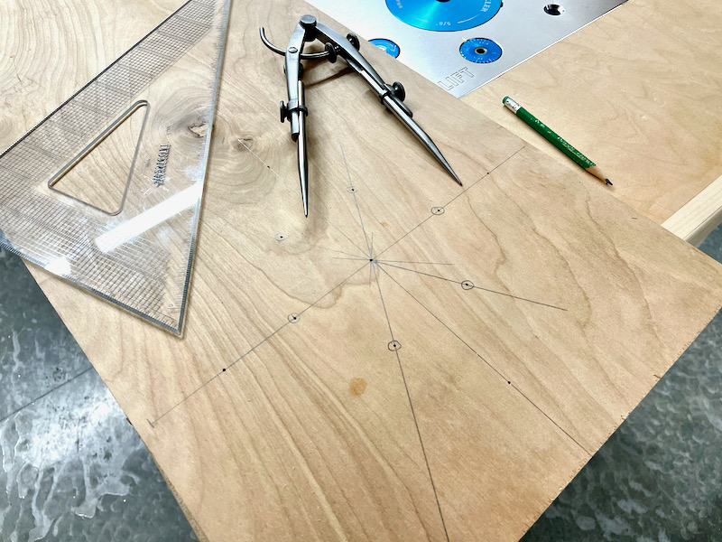
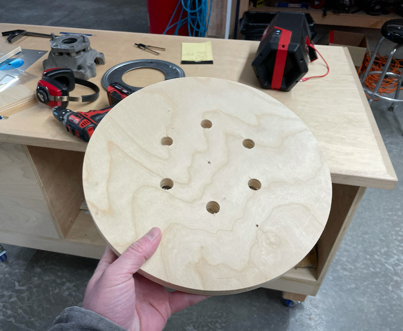
First I marked a center point on a piece of 3/4" plywood, and laid out six holes spaced every 60º around a 4.75" diameter circle, matching the Hartzell K/R prop hub mounting bolt pattern.
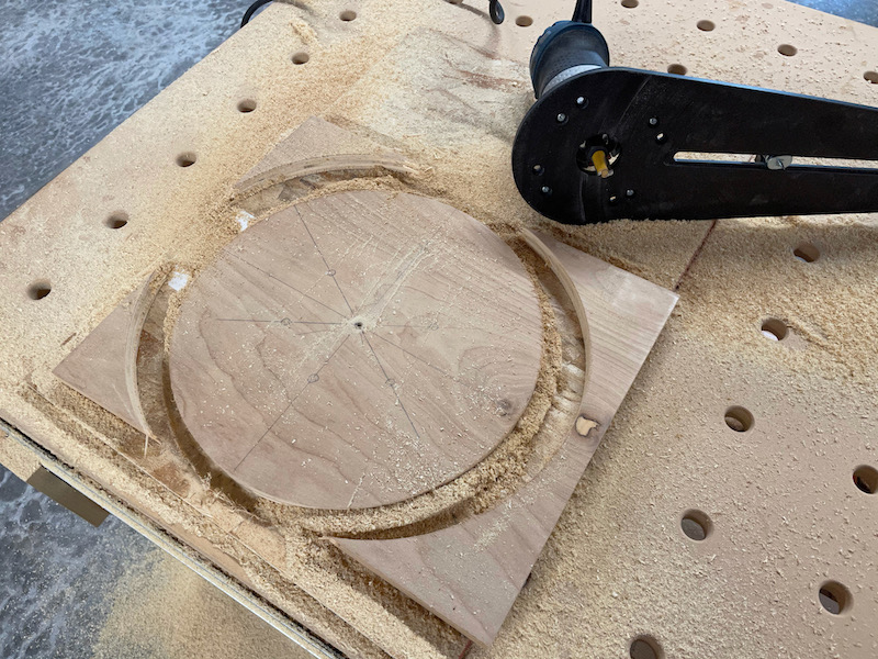
Then I turned it into a 13" diameter circle using a router and circle jig. This part doesn't have to be perfectly circular, so you could use a jigsaw or a bandsaw – I just happened to have this tool on hand.
Then, using a drill bit through the center as a sort of axle, I drilled six 5/8" holes. The actual prop bolts are 1/2", so this gives some wiggle room which becomes important later.
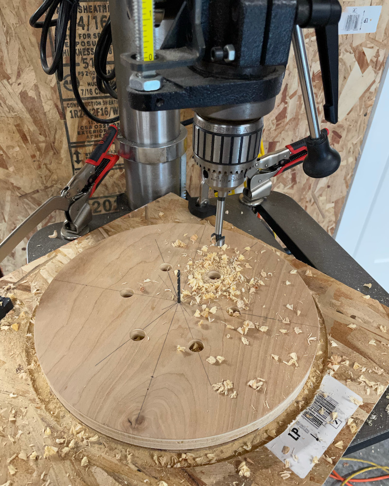
The finished plate:
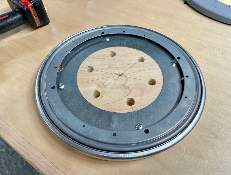
I then mounted this with short wood screws to a swivel bearing which I sourced from my local hardware emporium. I did my best to align the center of the plate with the bearing's axis of rotation, which I achieved by lining up the four screw holes with reference lines that I'd previously marked through the center point.
Next I grabbed another piece of plywood from the scrap pile – this was around 18" by 5 feet, but the exact size isn't strictly important. In this I cut a hole whose diameter was roughly the same as the open part of the swivel bearing:
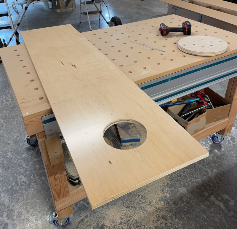
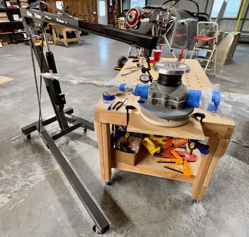
In the photo above you can just see where I drilled two extra holes near the circumference of the plate, which are necessary to attach the swivel bearing to the long board. I clamped the resulting jig to the bench with the bottom hole halfway hanging over the edge, and then bolted the propeller to the top plate. Voila, a prop rotisserie:
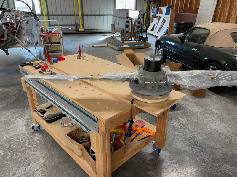
Important note: Obviously with your expensive propeller hanging partway off the edge of the table, you want to be sure the jig is firmly secured in place! I wouldn't suggest using it as a chin-up bar either.
The prop is secured to the rotating plate from underneath using hardware-store nuts and washers. You don't get full thread engagement through the nuts, but it doesn't matter for this application.
I know what you're thinking – a pile of wood and a Lazy Susan bearing from the hardware store, how accurate can this really be? Well, as it turns out, it's plenty accurate enough for this application. The bearing I bought is rated for a much heavier load than what the propeller weighs, so it turns very smoothly. There's also no side loading on the bearing, so I found that it turns without a noticeable amount of slop.
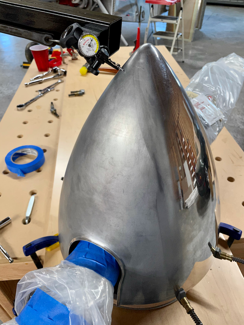
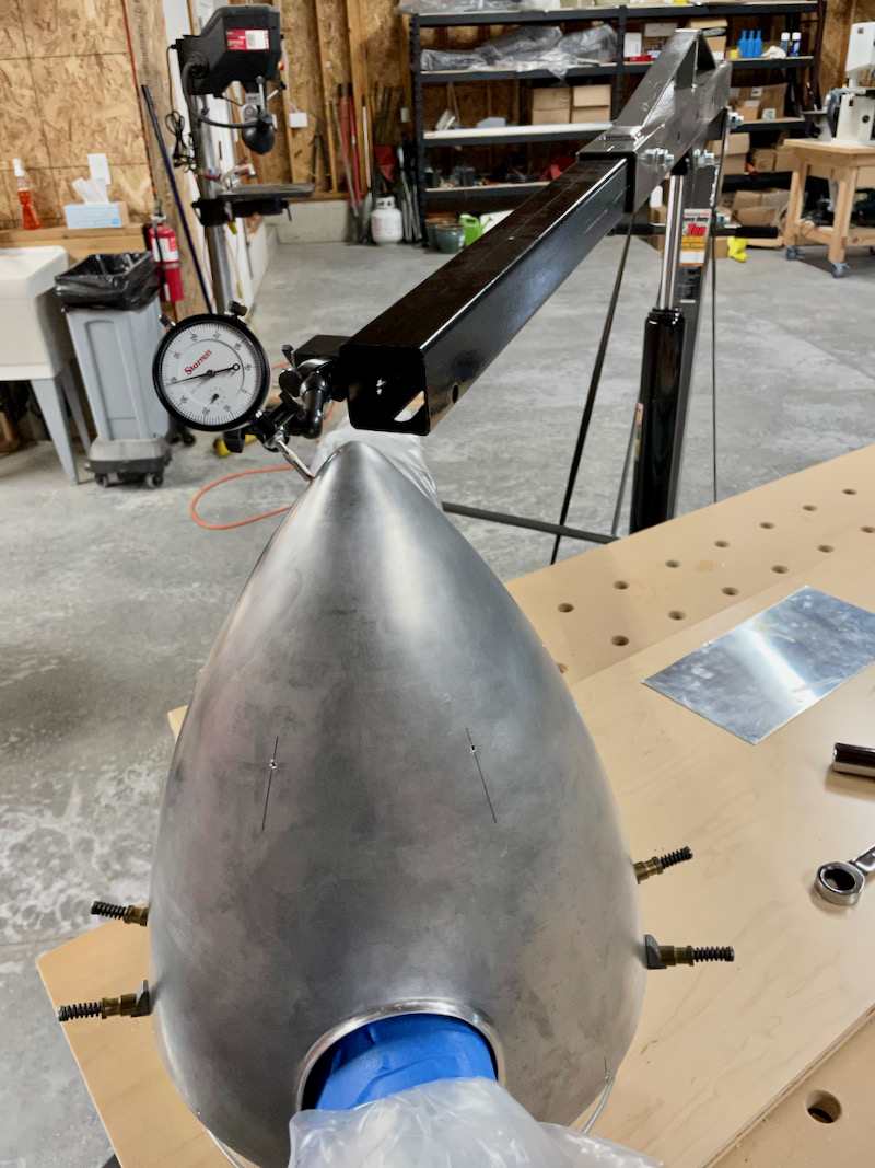
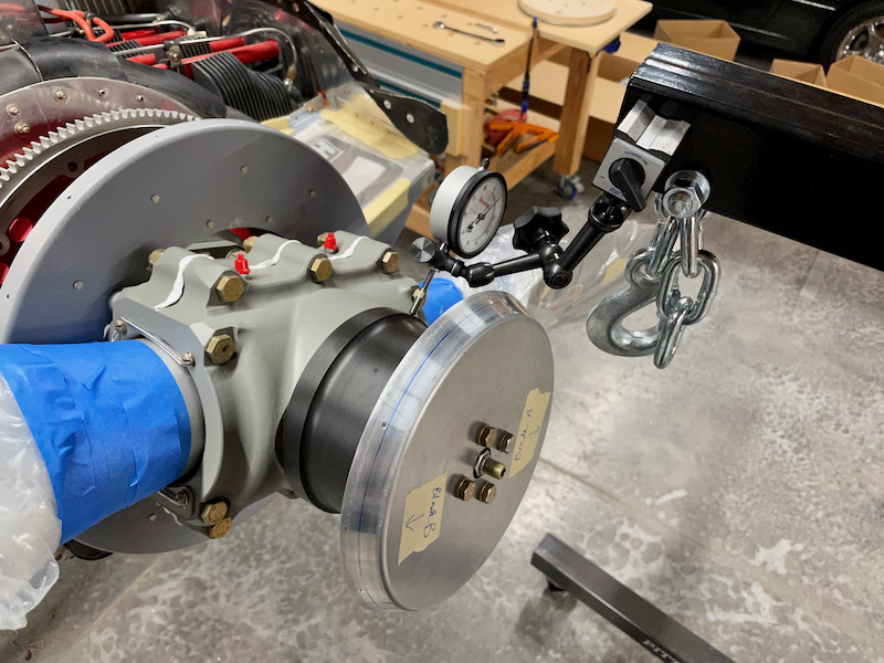
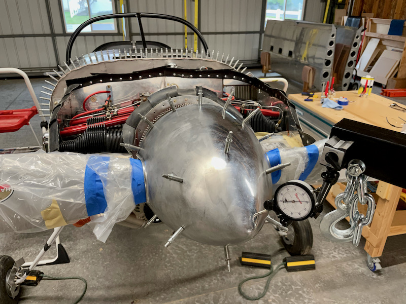
Anyway, we're not totally relying on the accuracy of the jig – instead, what I did was to iteratively tap the prop this way and that until I had it running as true as I could get it. It may or may not be perfectly centered on the plate, but what's important is that it's centered on the bearing's axis of rotation. To do this I used a dial indicator on a long arm, which happens to also be my engine hoist:
Again, I know what you're thinking, especially if you're a real machinist – a wobbly Harbor Freight engine hoist is a terrible indicator stand! Well, yes, I agree with you, but for my purposes here it's good enough. If you look closely at the photo above, you'll see that I used a couple of bungee cords to take out most of the slop, which helps quite a bit. If you're careful and you avoid bumping it while you're measuring, it does a good enough job.
The steel engine hoist also provides a convenient place to attach a magnetic indicator holder – I used my nice Nogaflex holder and expensive Starrett indicator, but if you don't have these tools handy a cheap imported setup (such as this one) should be adequate.
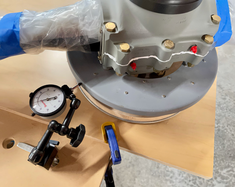
I used the base of the prop dome as my reference surface, on the assumption that it should be concentric with the prop flange and also smooth on account of being CNC machined. By carefully rotating the prop without applying any side load – use one hand on each blade – you can find the highest spot, which will be the farthest from center. Then you give the base of the prop a couple gentle taps with a mallet and a wood block, shifting the high spot towards the center. Repeat until you have as little runout as possible, and tighten the bolts. In my case I got it to less than ±0.010", which is basically within the measurement error of this Rube Goldberg setup.
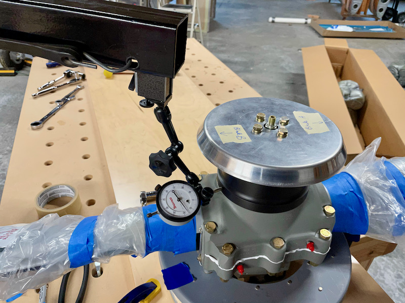
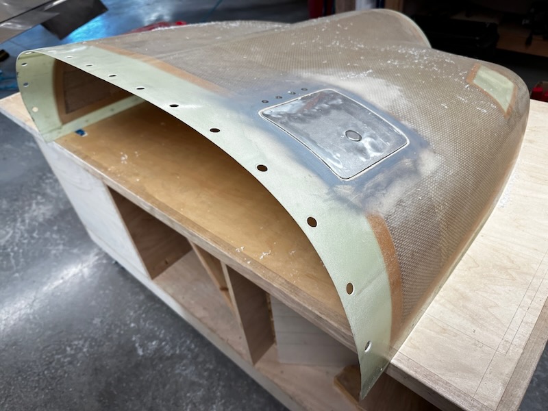
Once I had the prop running true in the jig, the next step was to use the indicator to get the front spinner bulkhead and backplate running true as well. (Obviously you have to have the backplate mounted before you attach the prop to the jig, or else you'll have to take it apart and align it all over again!) Here I'm indicating off the backplate, with the magnetic stand stuck to a steel clamp that I ran through in a hole in my table:
My backplate in particular had some surface variation that made it tedious to get centered, but I just did my best. I tapped it here and there until it was as centered as I could get it, then torqued the mounting bolts. For the front plate I found the most effective approach was to try different orientations until I found the one that made it run the truest, then marked that so I'd know how it should be clocked when removing and reinstalling it.
During this process I also did a test-fit of the spinner so I'd know where to position the front bulkhead. In my case I needed two regular AN960-416 washers between the bulkhead and the prop to make the spinner fit correctly, plus another regular washer and a -416L under the bolt heads. It's all iterative, I just took my time and measured a lot.
The astute reader might be asking at this point: Couldn't you do all this with the prop mounted on the airplane? Why bother with this rotating jig thing? Well, there are a few good reasons: A rigid jig clamped to a sturdy workbench provides a more solid base for accurate measurement, and with the prop pointing upwards you can use gravity to your advantage rather than having it fight you. There's also a third reason, which I'll detail shortly.
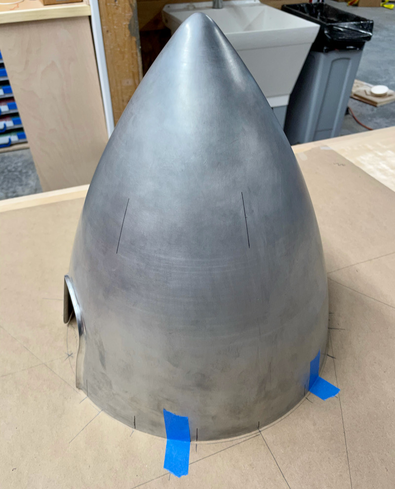
Anyway, once I was sure I had the front bulkhead and backplate aligned as accurately as possible, I needed to mark the spinner for the mounting screws. Actually it would have been better to do this as the very first step, so I could use the backplate underneath the spinner while I had it taped to the table, but it still turned out all right in the end. I used the Cummins instructional video as a jumping-off point, but ended up devising my own method of marking the hole locations.
Loosely following the installation guidance, I drew a 13 1/8" circle on a piece of butcher paper, and marked a center reference line. I then marked the locations of the seven screw holes on each side of the base of the spinner, with the end hole on each side being 3/8" in from the flanged blade cutouts. I used a pair of dividers to make sure I had identical spacing between every hole, and I also made sure that the center hole on each side hit the reference line exactly. Then, without moving the spinner, I also marked the six forward holes. The result is that that the middle screws on each side of the spinner are exactly lined up back-to-front, which pleases me. At this point I was only marking the hole locations in azimuth, not in elevation (i.e. distance from the base).
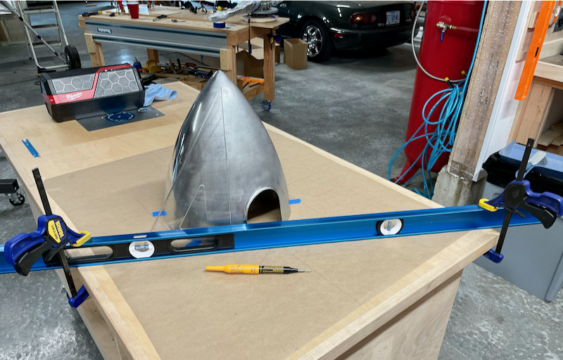
To mark the forward hole locations I used a big plastic triangle as shown in the Cummins video. Their suggestion is to use a second pair of hands to hold the bottom of the triangle against the spinner, but since I was working solo I just clamped my 6' level to the table instead.
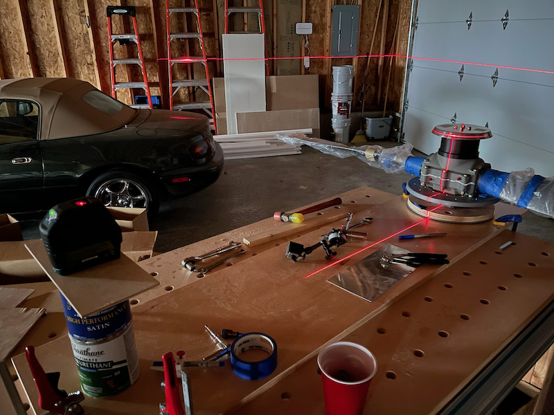
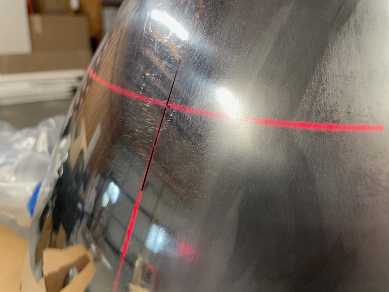
The trickiest thing about marking the spinner hole locations is finding the correct distance to the forward screws. With a fiberglass spinner you can pre-drill the holes in the bulkhead and then shine a bright light through from the back, but you can't do that with an opaque aluminum spinner. I was going to just blindly follow the recommended distance and hope for the best, but then I remembered that everything is better with lasers. With the prop still in the jig, I set up my laser level and projected a horizontal line onto the middle of the front bulkhead:
Then I carefully put the spinner in place on the prop, and marked the spot where the horizontal line crossed one of the previously-marked azimuth lines. The result should be the correct location of one screw hole.
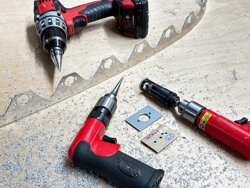
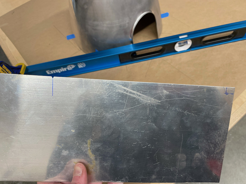
The laser setup was a bit too wobbly for me to trust it for marking multiple holes precisely, so instead I transferred the established distance between the laser-mark and the base onto a scrap piece of aluminum. Into the edge I filed a notch it to provide an accurate place for the tip of the marker to land, then used it to mark the locations for all six forward screws.
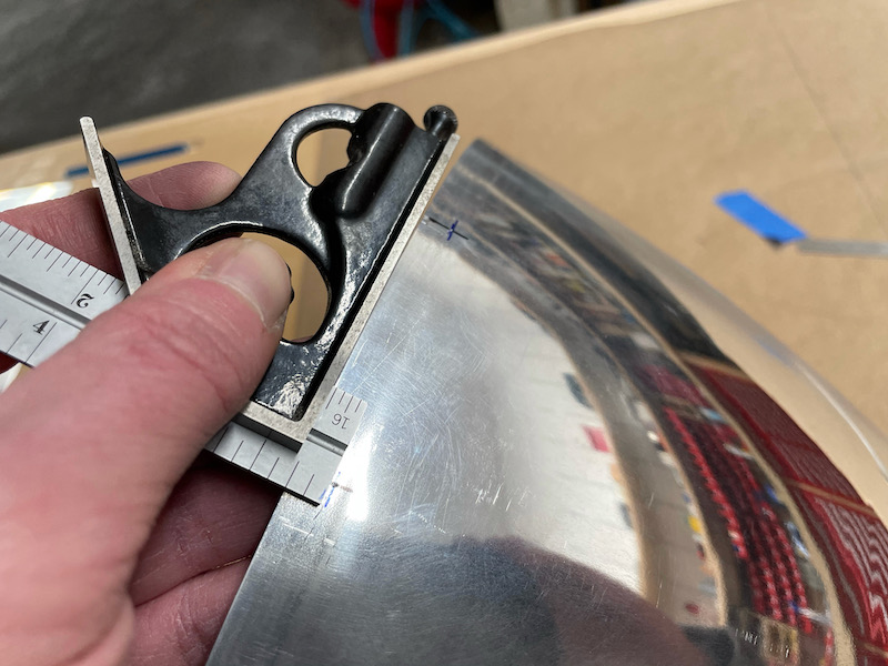
The rear holes were much easier – I just used a combination square set to the appropriate distance:
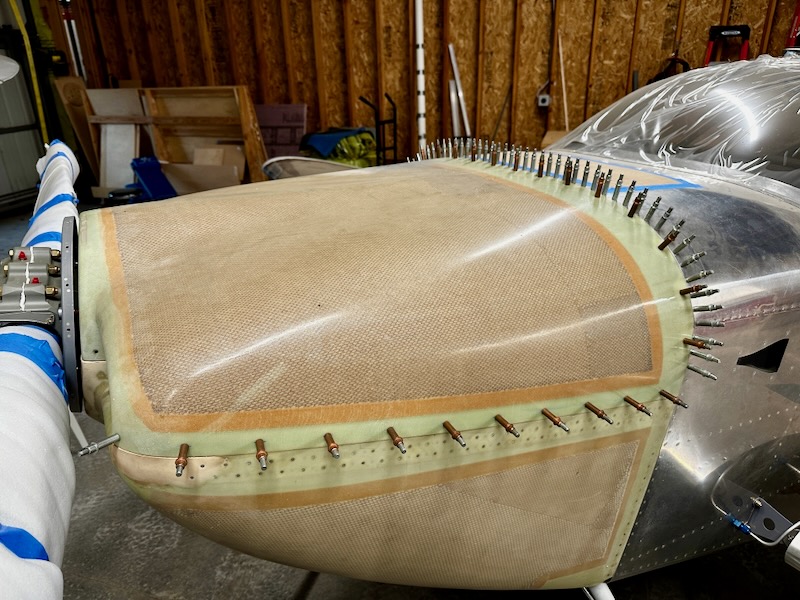
After taking a deep breath, I lightly scribed the marked hole locations to give the drill bit something to center on, and drilled #40 pilot holes through the spinner for all twenty screws. Then I clamped the base of the spinner to the prop backplate, and fiddled with the fit until I had it running as true as I could possibly measure.
Then I match-drilled into the front bulkhead and backplate, thus fixing the fit of the spinner to the prop:
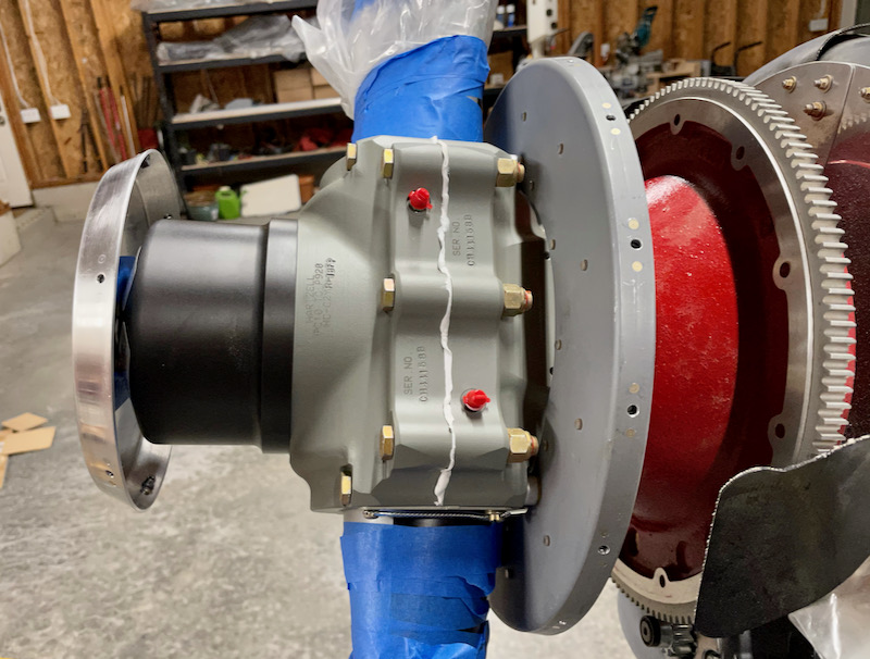
The next step was to mount the prop on the engine for final fitting. I unbolted the prop from the jig, hoisted it up to the crankshaft, and threaded in the six bolts, one tedious flat at a time. I used my Bogert prop sling for this, which was very useful for single-handed mounting of the prop without struggling or dropping something expensive.
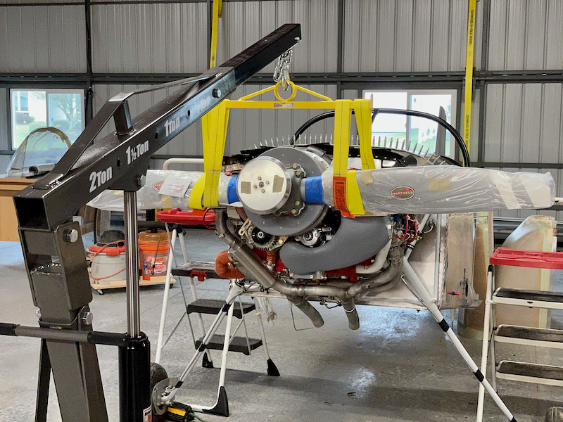
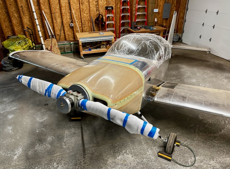
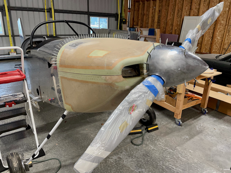
Prop mounted for the first time. Let's all just sit back and appreciate this milestone for a second:
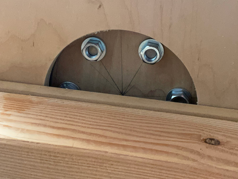
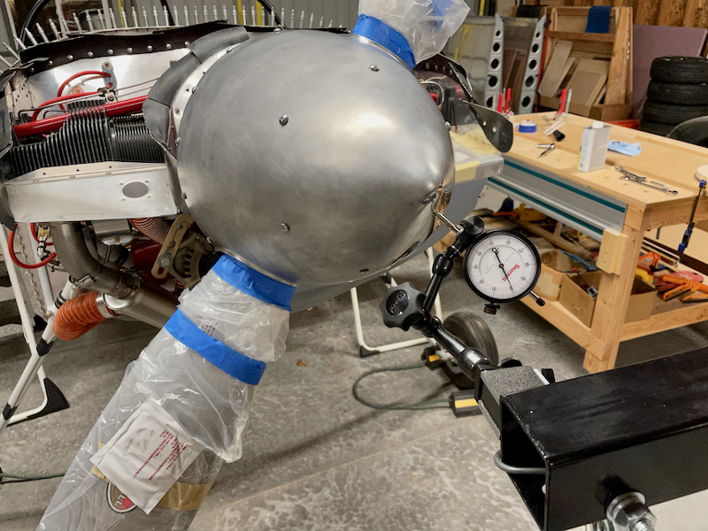
With the prop bolted to the engine, I turned it through a few revolutions (with the spark plugs removed) and used the dial indicator to verify that the prop dome runs as straight when mounted on the engine as it did when it was mounted in the jig. The measurements become more sloppy at this point – it's hard to spin the prop without inducing error when the airplane is sitting on rubber tires and the engine is on rubber mounts – but I did satisfy myself that the jig had been an excellent substitute for having the prop mounted on the actual engine.
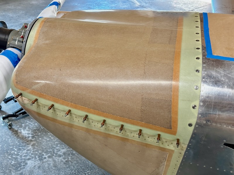
I clecoed the spinner in place and checked the runout again, with good results. Everything was just as I had measured it in the jig, just with noisier measurements due to the more flexible setup.
Just for fun, I threw the cowl on to see if it would fit. Good news, it fits fine. It's kind of fiddly to get everything aligned with all the rubber baffle seals folded the right way, but that's nothing new for an RV cowl.
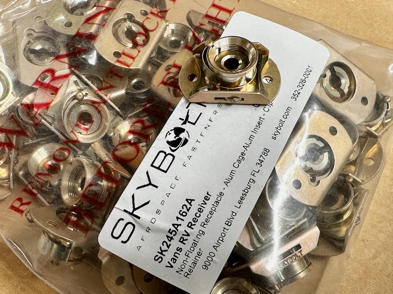
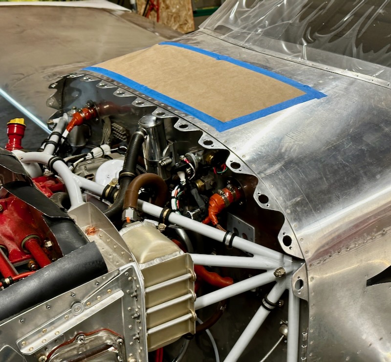
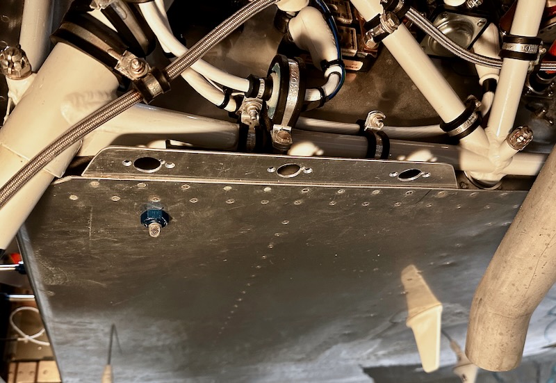
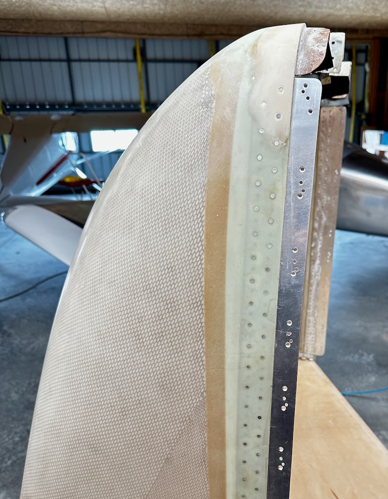
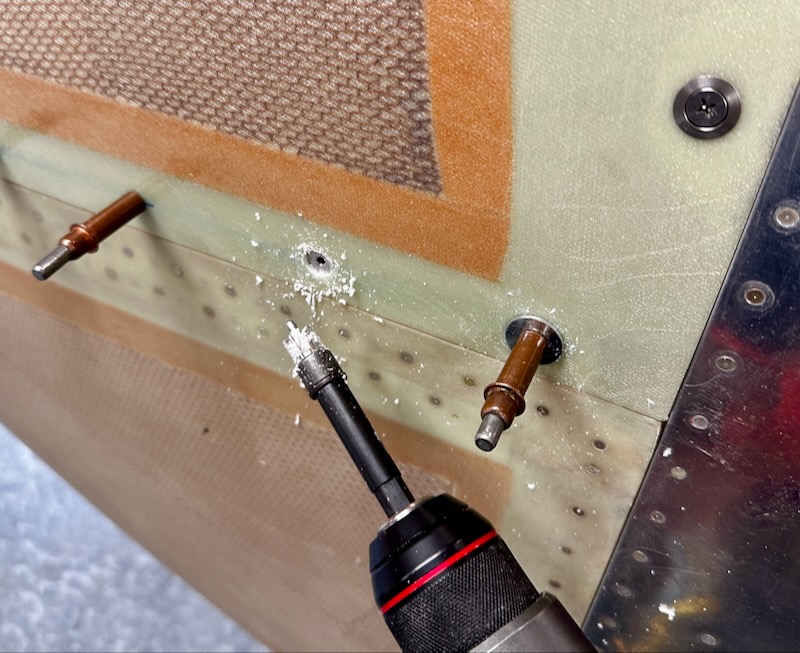
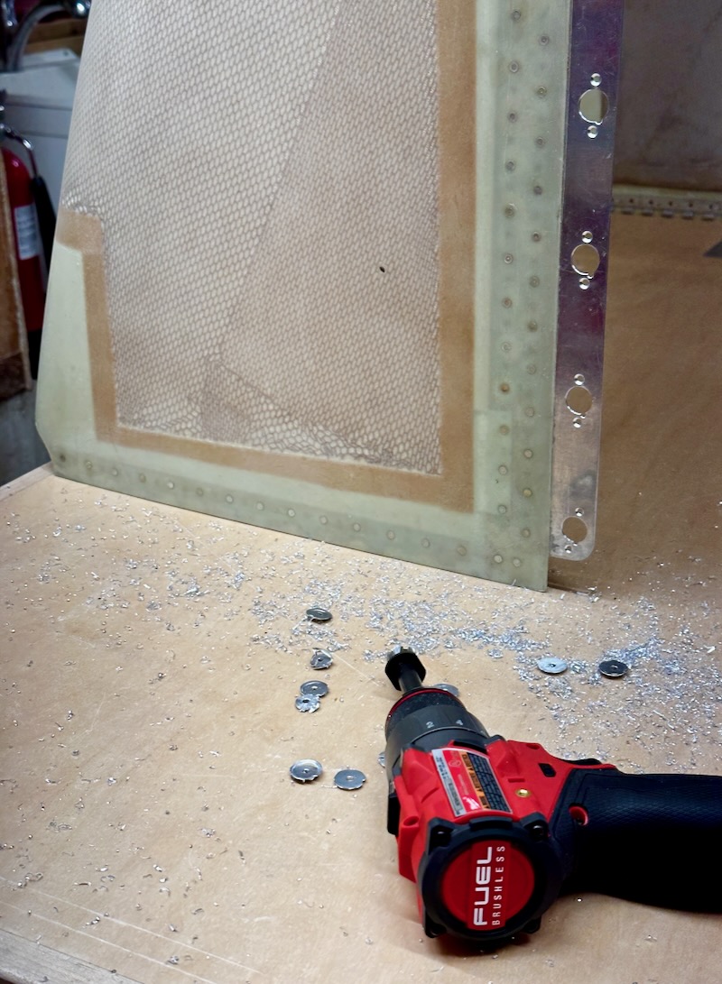
From there, the process of enlarging the holes to final size and installing nutplates followed the usual pattern. I was able to remove the front bulkhead to deburr and rivet the nutplates, but I left the backplate attached to the prop and just carefully did everything right on the engine. Drilling the holes in the backplate flange for the nutplate rivets was made possible by an angle drill.
And now, with the spinner completely fitted and affixed with the proper screws, one more measurement of the final runout figure. I ended up with a runout of approximately ±0.015", which is just about at the limit of my ability to measure anything at all. So, given the inherent inaccuracy involved in this measurement, I'm going to call that basically dead-nuts on. I'm very happy with that outcome, and it should hopefully result in a long-lived spinner with no cracks.
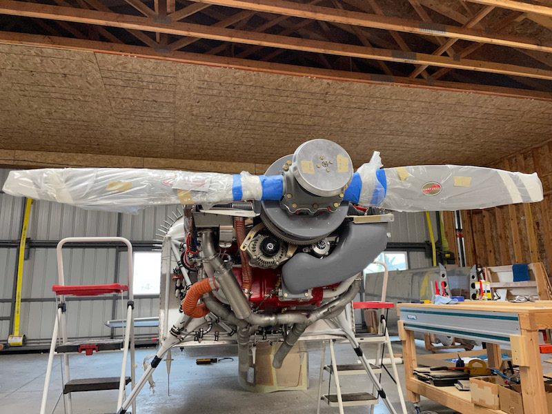
One final beauty shot of the prop and spinner mounted on the airplane, just because it looks cool:
Now, if you've read this far, did you happen to catch my mistake? Yes, I forgot to install the alternator belt before I mounted the prop, so it has to come off one more time before I can install it for good. Not a big deal, just annoying. I also need to safety the four bolts in the forward bulkhead, but I'll get to that soon.