Unless you drive some kind of classic antique, your car most likely has a system of plumbing and valves that takes crankcase blow-by gases and circulates them back into the engine intake to reduce pollution. On airplanes we just dump them overboard, because – as with many other aspects of aviation – that's how granddad did it back in the 1930's and by golly that's how we're going to keep doing it forever.
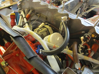
This takes the form of a "breather tube", which comes out of the top of the engine accessory case and is typically routed out the bottom of the cowl into the slipstream. As a bonus, the Lycoming engine also tends to spit a fine oil mist out the breather as well, which inevitably ends up all over the belly of the airplane.
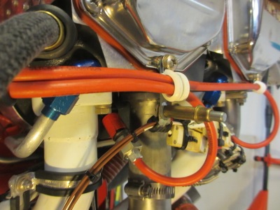
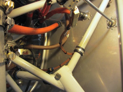
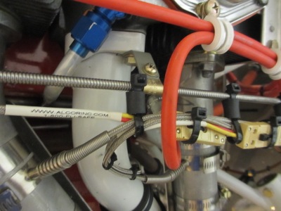
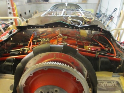
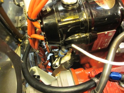
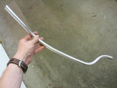
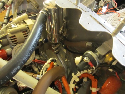
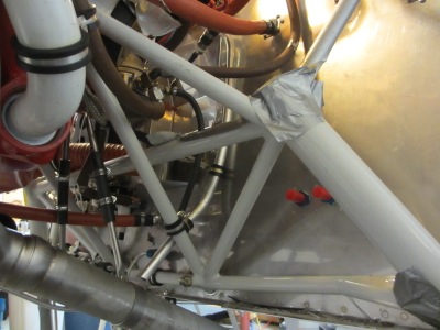
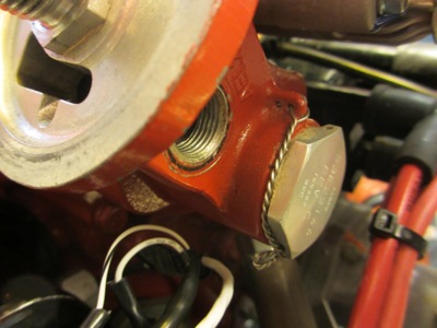
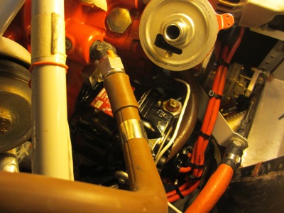
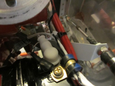
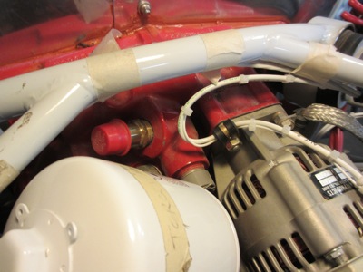
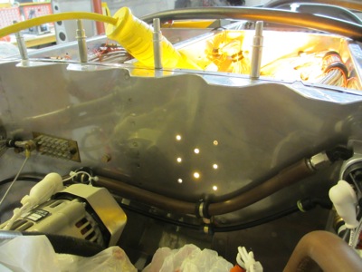
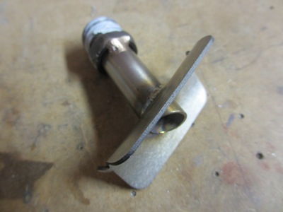
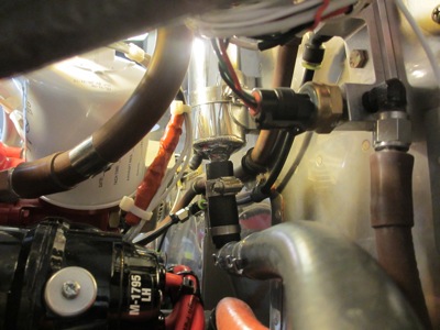
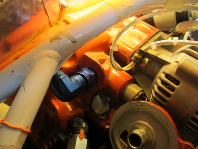
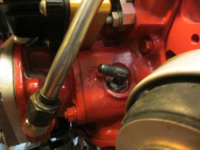
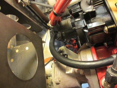
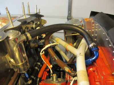
At the source of the breather tube, my engine came with a straight 3/4" brass fitting that sticks out of the accessory case at an angle… and dead-ends right into the engine mount. Uh, that can't be good.
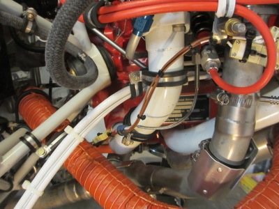
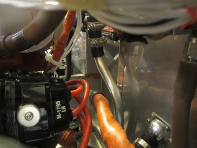
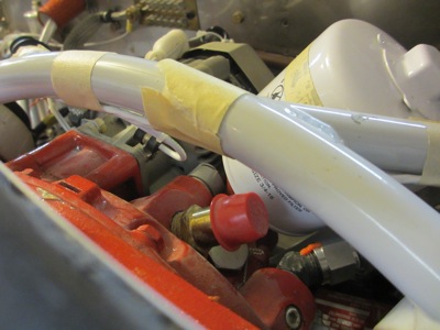
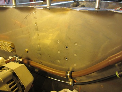
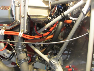
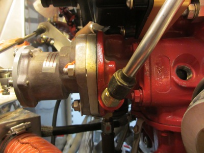
Another view looking aft. Not many options to attach a hose here.
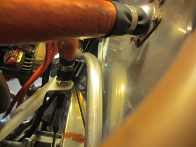
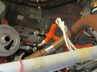
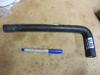
The Van's solution to this problem is to use a pre-formed piece of rubber hose to take a sharp bend immediately after the fitting, just barely clearing the engine mount tube. This is the actual hose they include in the firewall forward kit, although you can obviously see the NAPA auto parts label on it. The problem is that automotive heater hose isn't compatible with petroleum-based fluids, which includes oil – it breaks down into a gummy mess after only a few hours. In fact, a Van's employee is even on record saying not to use this same material that Van's supplies. (Dear Van's, I love you guys, but you all need to get on the same page!)
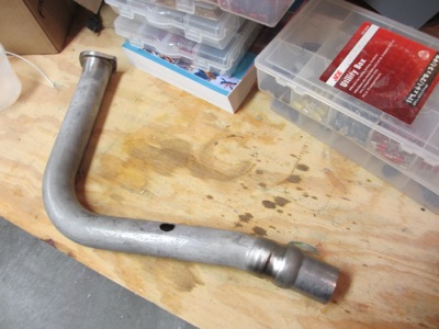
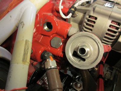
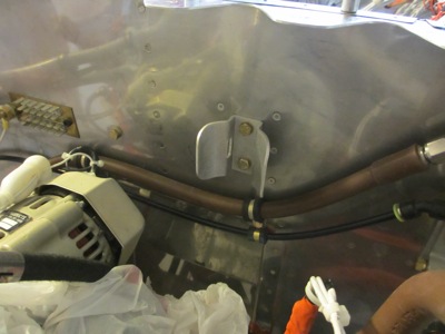
I decided I would be better off using the proper type of hose, which necessitated a different fitting. First I had to remove the old one, which was very challenging given the limited space to work in. Actually it was tough to even get a wrench on it, and that sucker was in there tight. Finally after plenty of Liquid Wrench and the most force I could muster without rounding it off, the fitting came out.
And then after that, I fooled around for a week with various arrangements of fittings and tubing and hoses, trying to follow the plans method to get the breather line from the top of the engine to the firewall and down to the exhaust. The problem I kept running into was that the prop governor cable was always in the way, so I couldn't easily get the plumbing to go where it needed to without hitting something else. I think I probably could have come up with a solution eventually, but instead I started thinking, is there a better way to go about this?
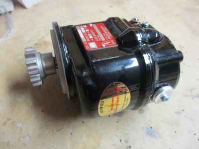
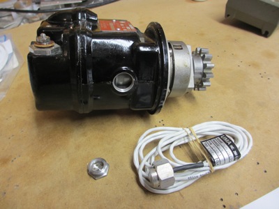
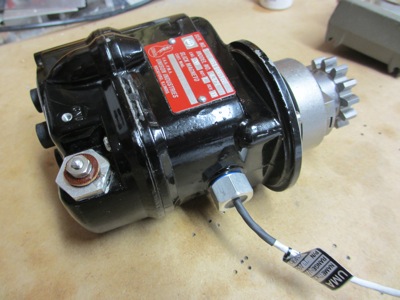
Then, because I'm a glutton for punishment, I ordered an air-oil separator from the oddly-named Anti-Splat Aero company. The idea behind this system is that a centrifugal separator divides the air-oil mixture into its component parts, and returns the condensed oil vapor back into the engine. Out of respect for hallowed aviation tradition, the combustion gases still go overboard and pollute the environment, but at least the oil stays off the bottom of the airplane. At least that's the theory, we'll see how well it works. Field reports seem generally pretty positive, so I'm cautiously optimistic. The more immediate benefit to me is that this uses an entirely different arrangement of hoses, thus allowing me to take a different route around the problematic prop cable.
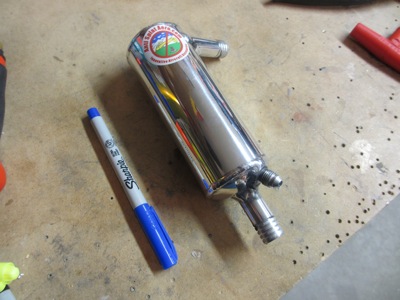
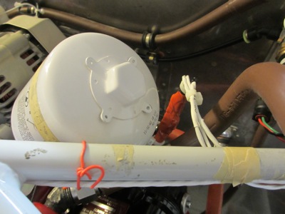
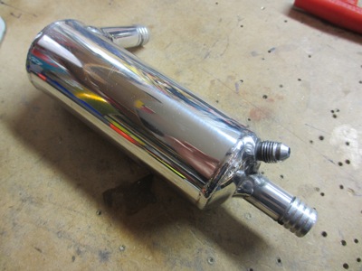
I don't like logo stickers, but fortunately theirs was easy to remove with acetone. Also, I ordered a white powder-coated oil separator, but they sent me the mirror-polished version. Whatever, it looks fine either way.
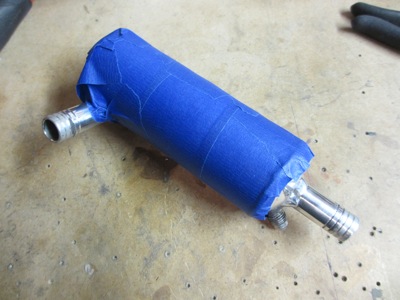
To protect the shiny finish I covered it with tape, which got progressively more dinged up as I experimented with mounting options and hose routing choices.
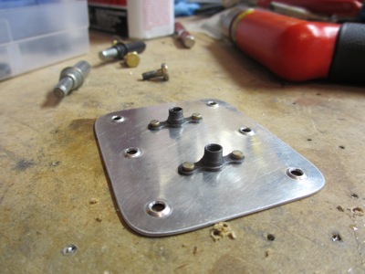
The oil separator needs to be mounted in a high spot on the firewall. It's pretty light, but I still didn't want to rely only on the 0.016" stainless firewall material to hold it up. I also wanted to use blind fasteners if possible, to ease future removal if required. So, I made up a little doubler out of scrap aluminum, and riveted a pair of nutplates to it.
To find the correct mounting location on the firewall, I first temporarily clecoed on the cowl fastener mounting strip. That let me figure out where I could position the separator, so it could be mounted as high as possible and still not interfere with any of the cowl fasteners that will eventually be riveted to this scalloped strip. Drilling the holes was yet another place where an angle drill came in handy.
I thought I might be able to use solid rivets to fasten the doubler to the firewall, but there's just too much stuff in the way to use a rivet gun and bucking bar. Instead I used Cherry Max blind rivets.
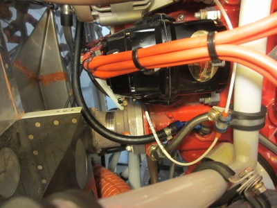
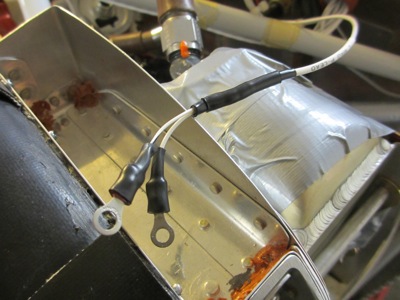
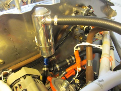
The oil separator clamps to an aluminum mounting bracket, which is bolted to the firewall via the nutplates that were just installed.
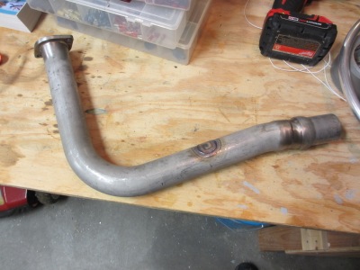
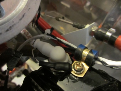
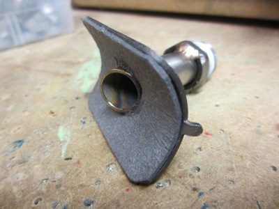
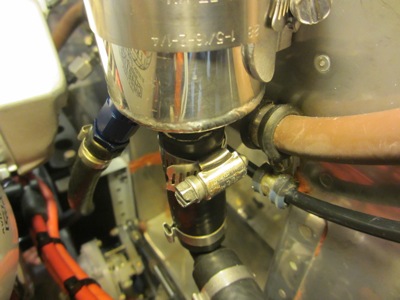
An important component of the whole system is this exhaust check valve and its associated mounting hardware. Instead of dumping straight overboard, the gas outlet tube from the oil separator is plumbed into the exhaust system through the check valve. This helps to burn up any remaining oil vapor before it can be deposited on the belly, and in theory also helps pull a mild vacuum on the crankcase due to interaction with the exhaust pulses. This may or may not have a beneficial effect on efficiency, but probably at least helps to keep oil leaks under control. The check valve is of course there to prevent the exhaust from pressurizing the crankcase.
The mounting tube faces aft and is cut at an angle relative to the exhaust stream, which helps pull gases into the exhaust pipe (see here for more information).
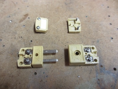
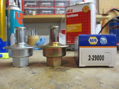
I had a suspicion that the valve supplied by Anti-Splat is the same as a NAPA part number 2-29000 smog valve, so I bought one just to take a look. It sure looks similar to me… supplied valve is on the left, NAPA valve is on the right:
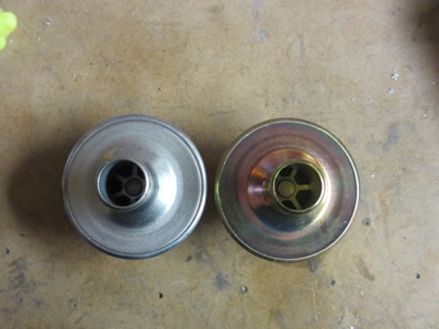
They appear similarly internally also. This is good to know, since at eighteen bucks the NAPA valve will be cheap enough to replace every annual or two. Anti-Splat sells the (seemingly) identical part for $69, so if you were so inclined you could probably get by with ordering only the mounting tube and then buying yourself a valve at your local NAPA.
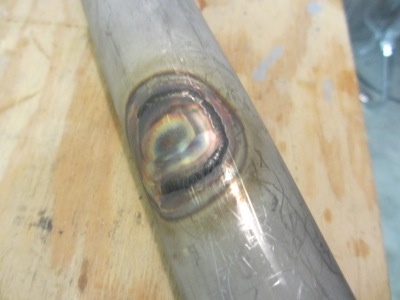
The innocent phrase "plumbed into the exhaust system", tossed out so casually above, implies a lot of head-scratching in order to try to find a place to mount the check valve where it doesn't run into anything else, followed by plenty of nail-biting and bad-word-uttering as you attempt to drill a bloody great hole in the side of a piece of expensive steel tubing without removing it from the airplane. I managed to get this done with a unibit and a long drill extension, but it was a pretty close shave.
Close-up of the hole. It's actually an oblong shape, due to the way the tube is angled. I used a dremel with a grinding stone to turn the round hole into an ellipse, followed by a scotchbrite drum to deburr and polish the edges. Also, apparently I left some of my blood behind. It's not the first time that's happened and I'm sure it won't be the last. Airplanes have sharp edges everywhere.
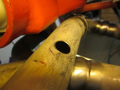
I didn't like the fact that there was no way to ensure the hole in the exhaust will be sealed, so I used a square of 1/16" thick asbestos gasket material between the mounting saddle and the exhaust. Well, not asbestos, but whatever they're using instead of asbestos these days. Unicorn hide, probably.
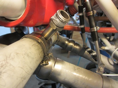
The check valve mounting pipe is attached to the exhaust with hose clamps. Hose clamps are safety-wired for security.
The gas discharge tube comes out of the bottom of the oil separator, which causes it to point towards the ever-troublesome prop governor cable. To turn it in a different direction, I used a plastic heater hose elbow from the local auto parts store. At first I was concerned that it might be too fragile for this application, but I had to manhandle it pretty roughly to get the hoses installed and it held up like a champ, so I'm no longer worried. The hose material here is MIL-6000, by the way… no radiator hose for me.
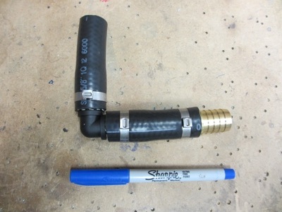
I also had to adapt the 5/8" hose outlet on the oil separator to the 3/4" hose required by the exhaust check valve… even though they are sold as a matching set. (why??!?) For this I used a brass 5/8-to-3/4 hose coupler just after the elbow. This whole business is a pretty Rube Goldberg way to turn a hose 90 degrees and step up to different size, but I couldn't find any single fitting that would allow me to do this in a way that was both more compact and also not any heavier.
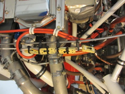
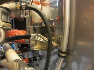
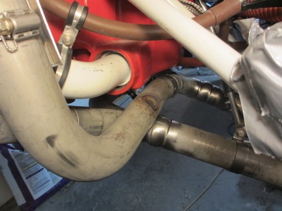
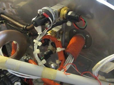
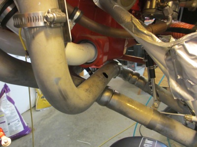
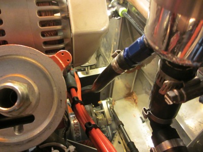
The hose runs straight down out of the oil separator, then immediately turns 90 degrees and heads outboard, paralleling the prop governor cable. (The hose clamp shown here isn't tightened yet)
From there the hose is secured to an engine mount tube with a pair of adel clamps, and then it turns downward to the exhaust check valve.
Check valve and hose installed. There's a decent amount of clearance all around, and the hose doesn't rub on anything. Good enough.
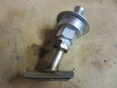
Meanwhile, back to the top of the engine, where we still need to install a usable fitting for the breather outlet. I chose a 90-degree swivel elbow from a racing supply outfit. 1/2" NPT on one side, -10 AN flare on the other.
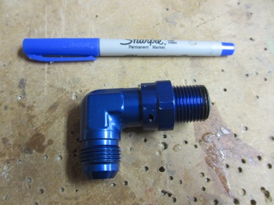
This fitting was pretty easy to install, since you can torque down the pipe thread portion without rotating the whole fitting. Without using a special swivel elbow, installation would be impossible due to the engine mount being in the way. Permatex #2 was used on the threads to avoid leaks.
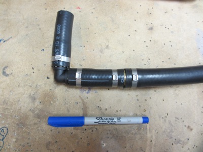
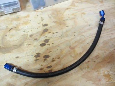
The mating hose for the breather outlet is composed of a 90 degree hose end from the racing supply house – one of my many orders this month – and a length of Parker 801 hose. This stuff is a bit lighter and quite a bit more flexible than MIL-6000, while still being able to withstand exposure to oil.
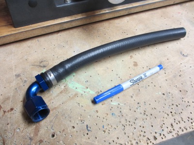
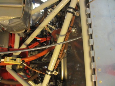
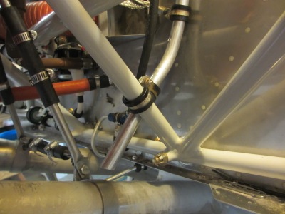
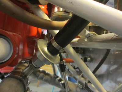
The 90-degree elbow on the engine, combined with the 90-degree hose end, allow a hose routing that goes forward underneath the engine mount before turning aft again and heading to the oil separator. Another Rube Goldberg arrangement, but I couldn't find a better way to do it.
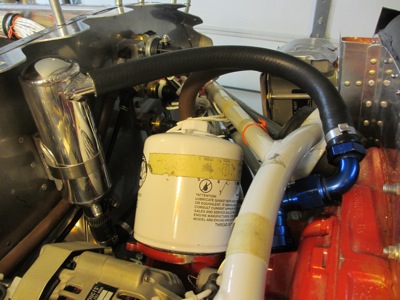
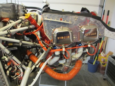
Another view from above. You can see here that the most obvious hose routing is blocked by the angle oil filter adapter, hence the somewhat convoluted approach I was forced to take. Further proof that the firewall forward area of the airplane is a zero-sum game… any item you install to make your life more convenient will cause exactly the same amount of inconvenience somewhere else! I suppose in theory it will all be worthwhile in the future when I'm changing the oil and the filter is so very convenient to get to. Someday. Maybe.
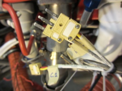
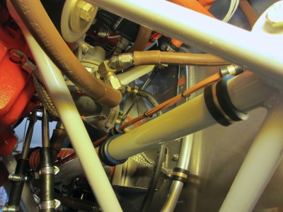
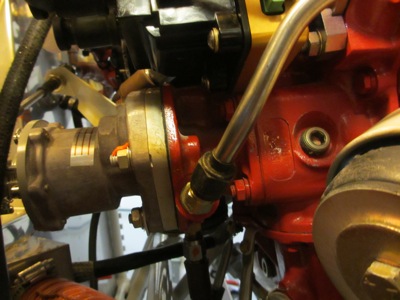
Two hoses down, one to go. The last hose required by the oil separator is a small drain line that returns the collected oil back to the engine. The recommended place to connect this hose is the turbocharger oil fitting on the side of the prop governor housing, seen here closed off by a brass plug:
It took a big socket extension, a flex adapter, and lots of elbow grease to get this plug out. I don't know what kind of sealant they used to use up at Mattituck, but it must have been good stuff.
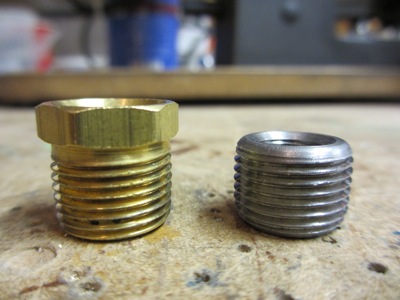
The hole in the engine has 3/8" pipe threads, but the elbow fitting that goes into it is 1/8" NPT. Obviously an adapter is required, but I was unable to find one short enough to also allow me to install the elbow fitting without having it hit the engine mount. Argh! In desperation I sent an email to the Anti-Splat people asking if they had a source for a shorter adapter that would fit. I never got a reply, but a week later an envelope containing a low-profile pipe thread adapter unexpectedly showed up in my mailbox. Okay, I'll take it! Normal sized adapter on the left, special short adapter on the right:
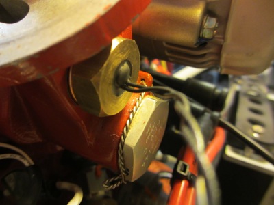
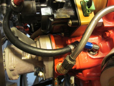
Elbow fitting installed in the engine, following some careful work with a crow's foot wrench and a long extension, plus another dab of Permatex. If you have a fixed-pitch propeller you can probably clock it straight backwards, but on my engine you can't point it straight aft since the prop governor is in the way. After much experimentation I chose to angle it slightly upwards rather than attempting to route the hose below.
I initially wanted to use standard aircraft hose for the oil drain line, but the angled fitting required to work around the inconvenient prop governor would have made it expensive. Instead I made the drain line using more fittings from the race shop plus a length of fuel/emissions hose (SAE J30R7) from the local automotive parts emporium. If this doesn't hold up in service I'll use it as a template to order a proper aircraft hose.
The oil drain hose has a straight fitting on one end and a 45-degree fitting on the other:
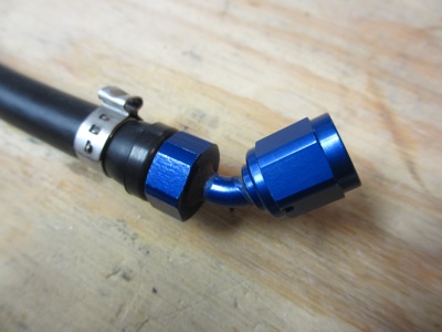
The 45-degree fitting is necessary to allow the hose to angle out and around the prop governor:
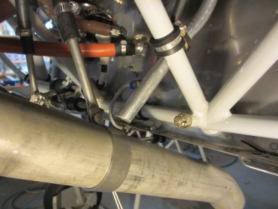
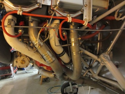
The hose then goes up and around the P-mag, just missing… well, everything really. It's crowded back there.
The hose continues up to the oil separator, managing to miss everything else on the way. My friend John once described the firewall-forward section of the airplane as "a bowl of spaghetti where none of the noodles are allowed to touch", and I think that's about right. Too many hoses, cables, and wires running through a confined space, and none of them can ever touch each other or they'll saw themselves in half.
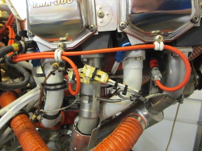
Finished! All hoses secured and clamped with Oetiker clamps:
…except this hose here, on which I used a normal band clamp due to space constraints:
What a relief it is to get this done and check another thing off the to-do list at last.
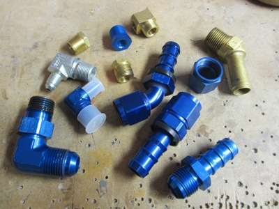
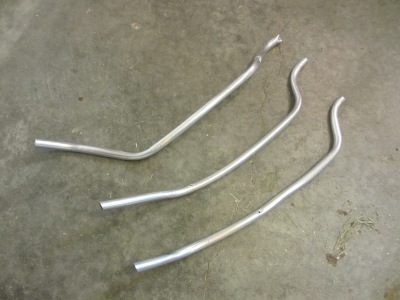
However, one thing to keep in mind is that I documented all of the above in a linear fashion, as if it all happened just that way. What I didn't show you was the weeks of uncertainty, frustration, false starts, backtracking, and scrapping of half-completed parts. This whole thing was a total ordeal, and pretty expensive to boot… since I didn't ever quite know what parts I was going to require, I ordered more than I thought I needed in the hopes that at least some of it would prove useful. Unfortunately I now have a big pile of leftover fittings which are going to have to go into my junk box miscellaneous parts container. Here's a representative sample of what was left on the cutting room floor: