Archive for the ‘Fuselage’ Category

Flap pushrods

Sunday, June 25th, 2023

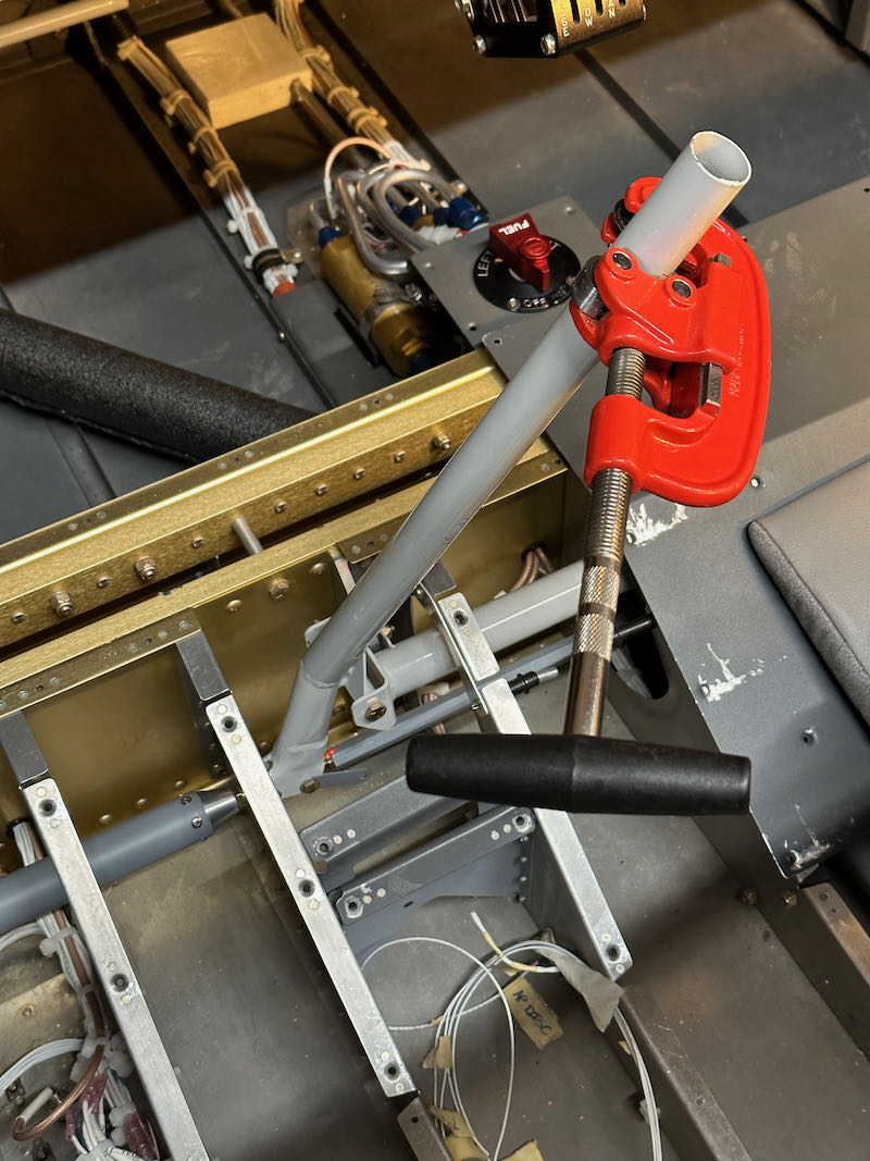
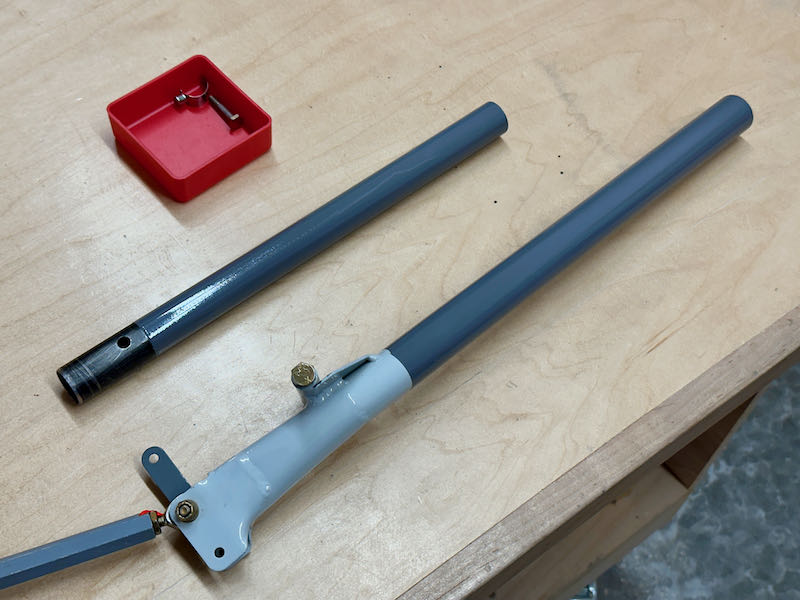
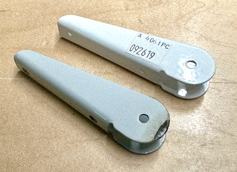
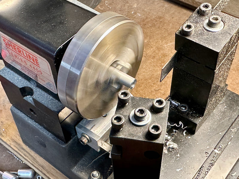
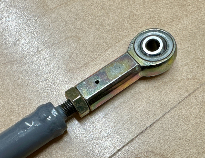
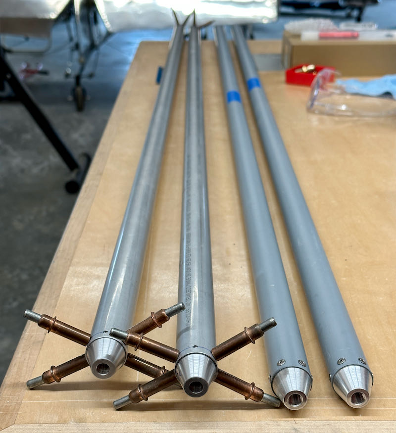
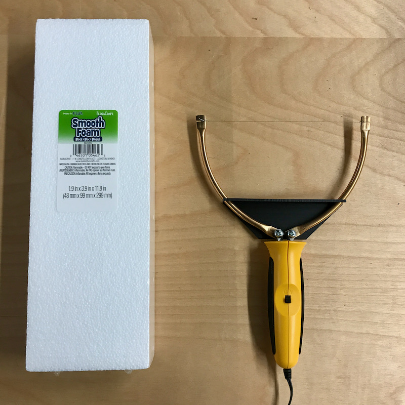
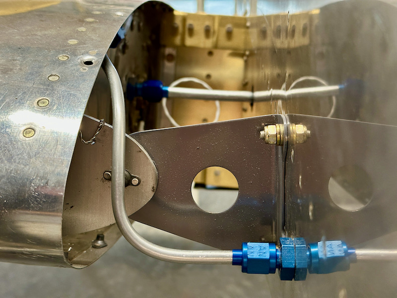
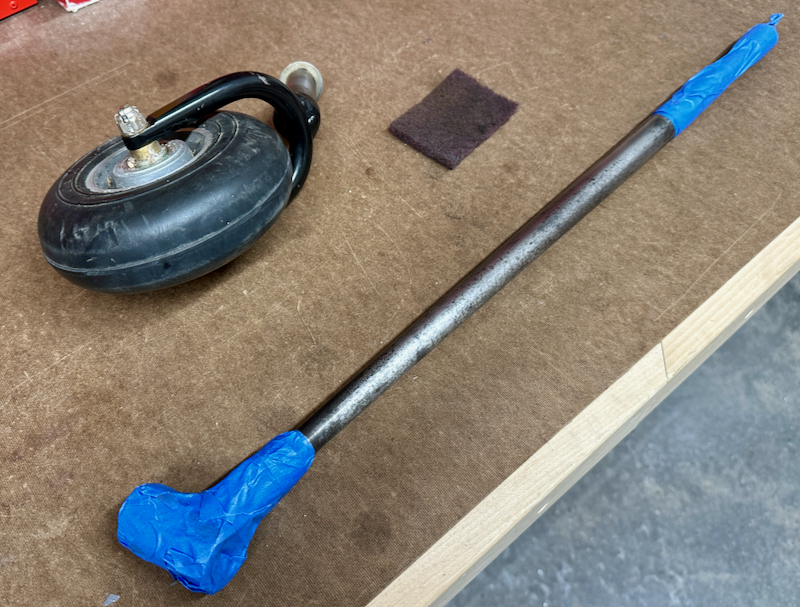
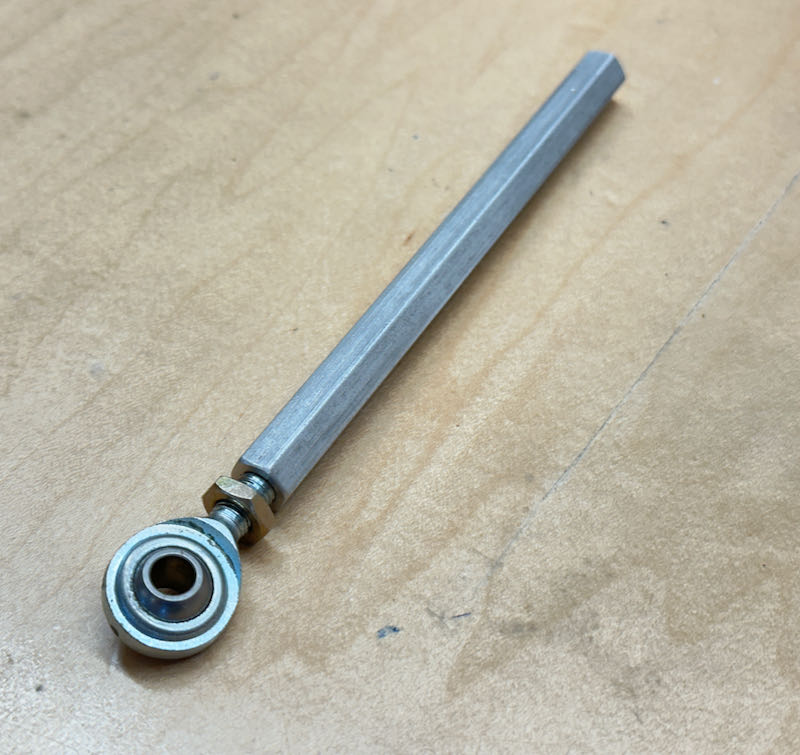
After trimming the flaps to fit nicely to the fuselage, the next step is to finish the mechanism that operates them. The RV-7 plans have you make a pair of pushrods by tapping the ends of some fairly skinny aluminum tubing, but I decided to follow in the footsteps of others and use the beefier hex stock normally used by the RV-9. Since the RV-7 uses shorter pushrods, the easiest way to do this was to simply buy the RV-9 parts and cut them to the correct length:

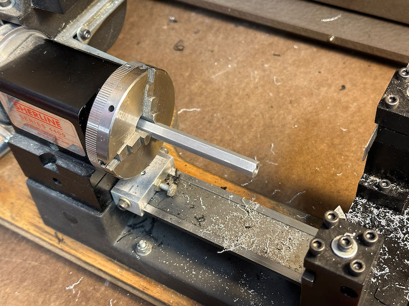
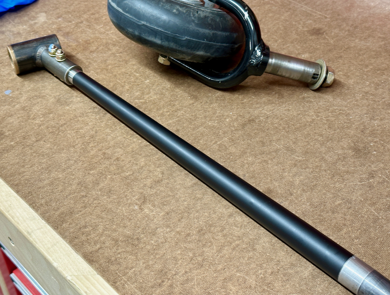
Real machinists are cringing at the unsupported length in the above photo, but since I didn't have a good way to support these pieces while facing the ends, I just took light cuts and worked carefully. Here's a finished pushrod with one rod end bearing installed:

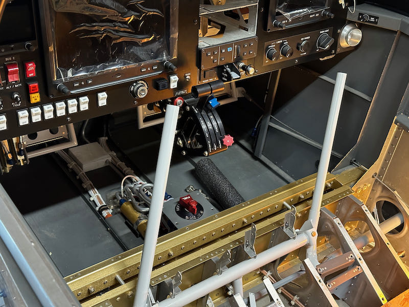
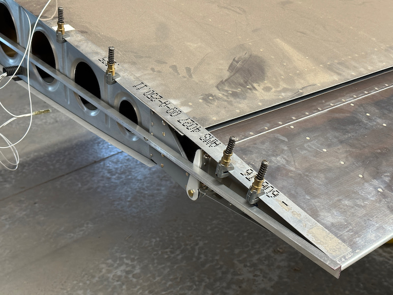
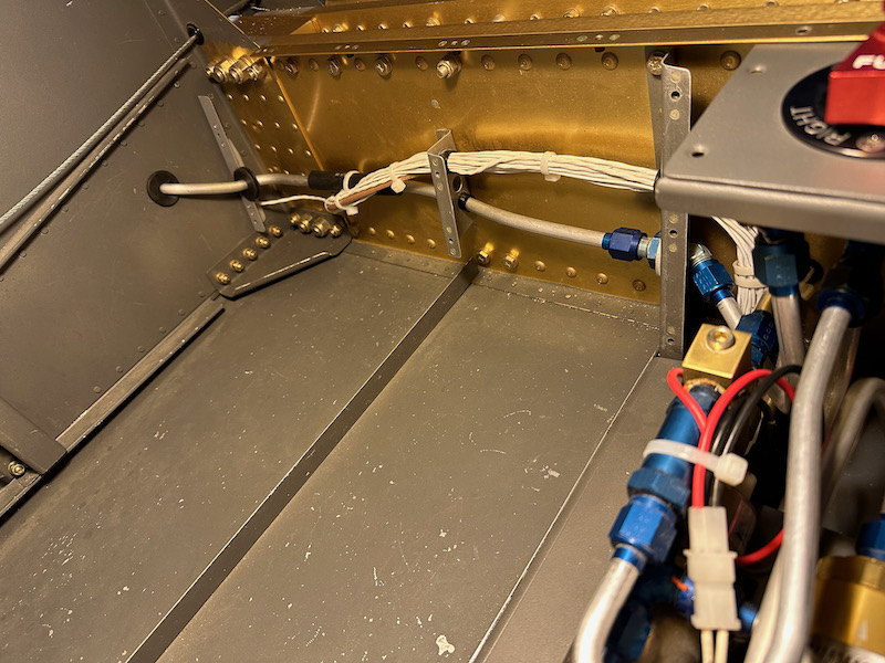
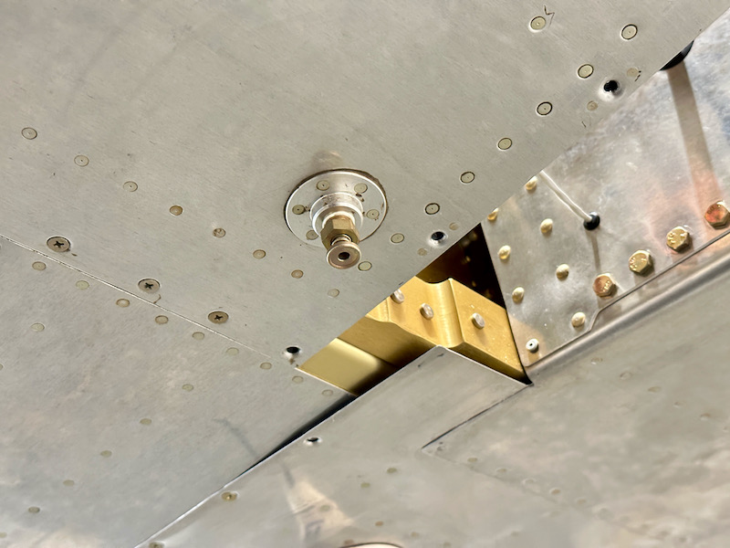
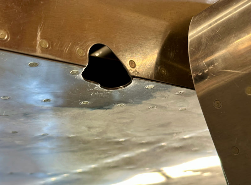
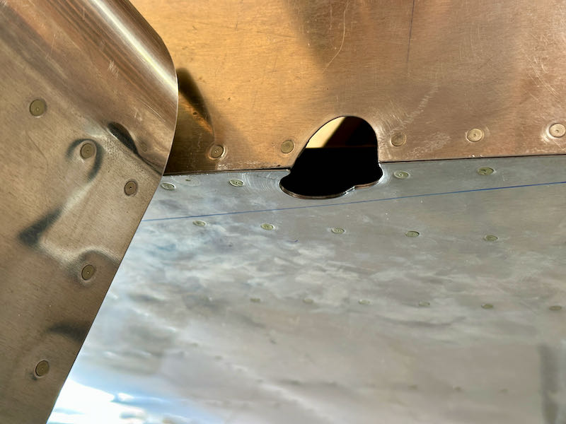
The most challenging portion of this part of the project was cutting the holes that allow the flap pushrods to pass through the fuselage bottom and sides without binding. I'm told that these are prepunched on the RV-14, which must be nice, since they have to be a strange 3D shape that can only be determined iteratively. I didn't take any pictures of the process, but there was a lot of tedious test-fitting, marking, and grinding until I achieved a satisfactory result:

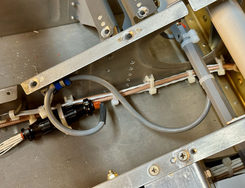
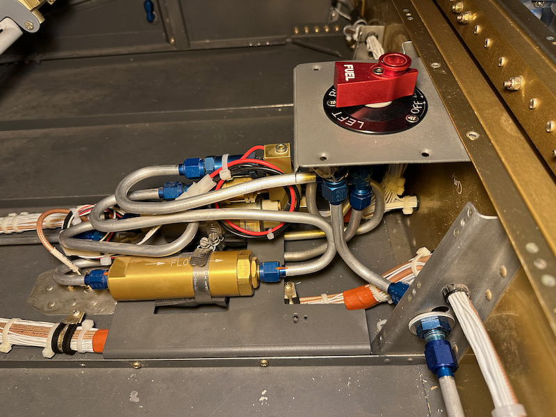
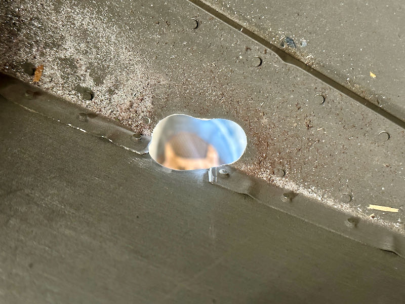
Here's a view of the same hole from the inside looking down. I still need to clean up the mess of aluminum dust and sanding-wheel particles from inside the fuselage:

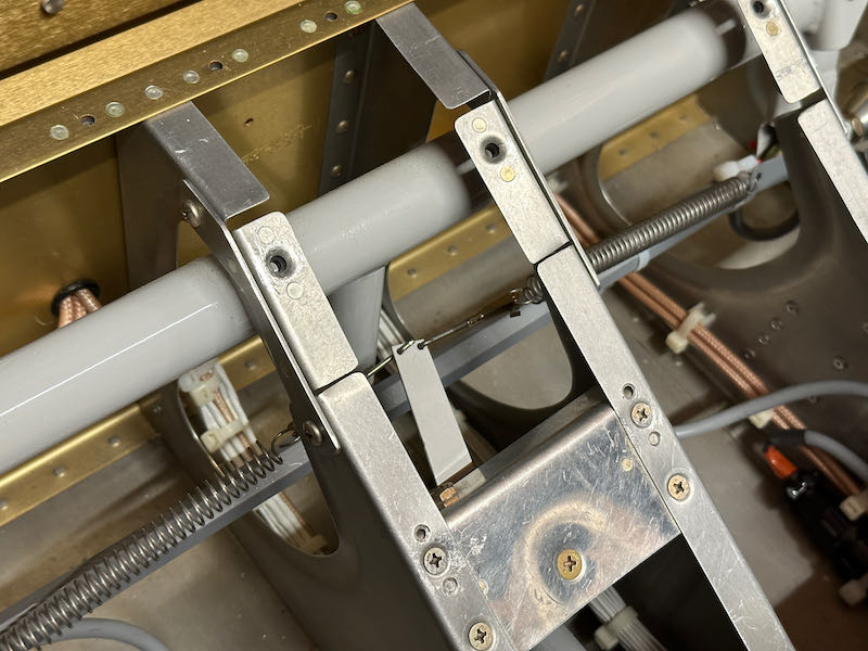
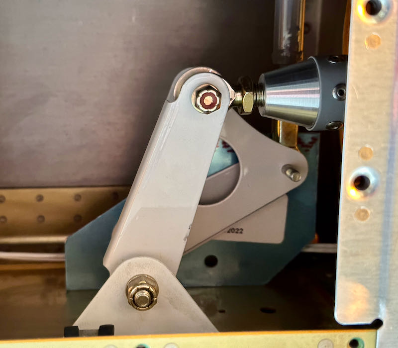
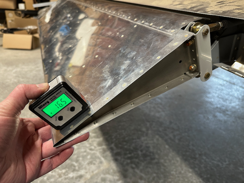
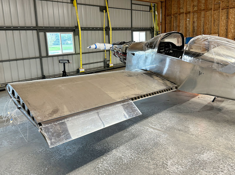
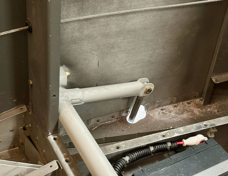
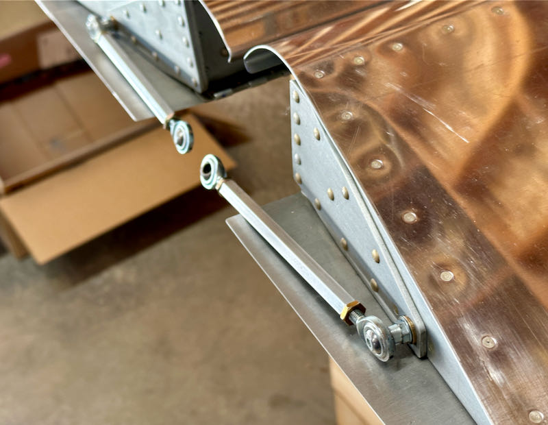
I must have installed and removed this pushrod a hundred times before I got the shape of the hole right. Here you can see that there is adequate clearance all around when the flaps are in the full-down position:

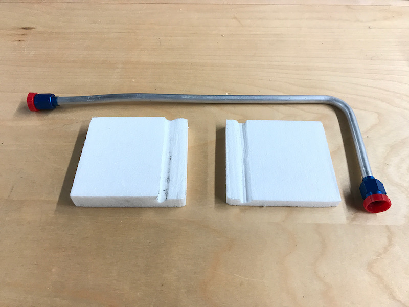
Finishing the first first hole took me an entire day and then some. Instead of starting from scratch on the second hole, I used a piece of manila folder to make a rough template that would give me a head start:

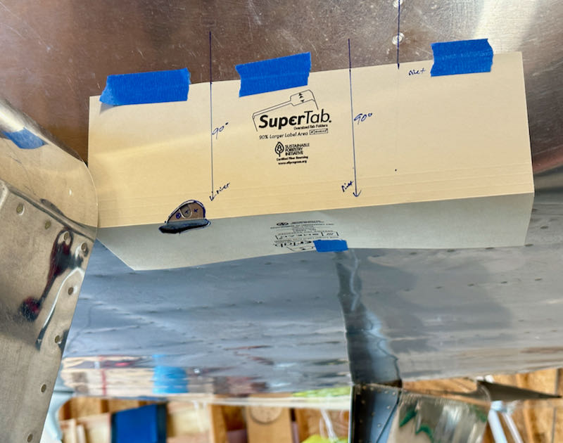
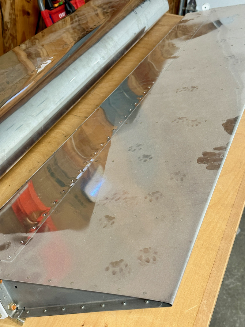
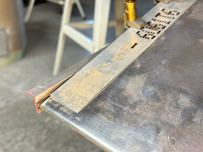
Here's the second hole, which only took me a half-day to finish. The blue line indicates where the flap bottom skin ends, showing that the hole will be completely hidden when the flaps are up:

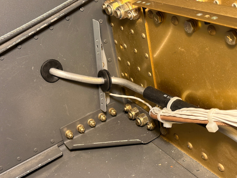
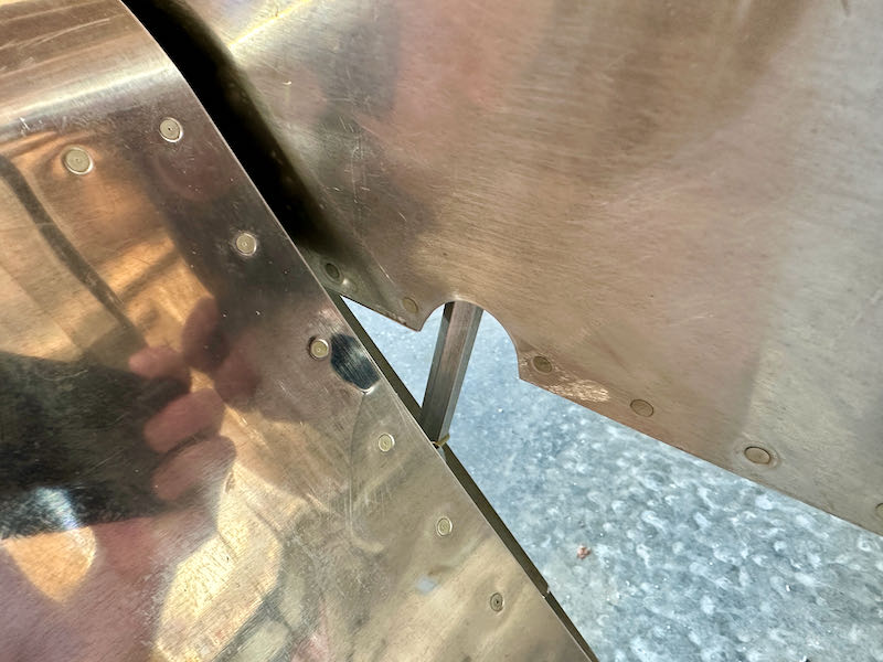
I have to say, this whole pushrod-hole situation seems like a real afterthought to the design, and the way they have you grind your way through the corner of fuselage is pretty barbaric. And I'm not just saying that because I slipped with the sanding drum and scuffed up the fuselage skin:

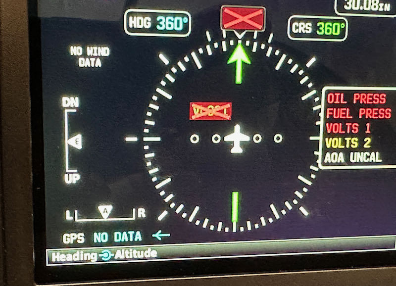
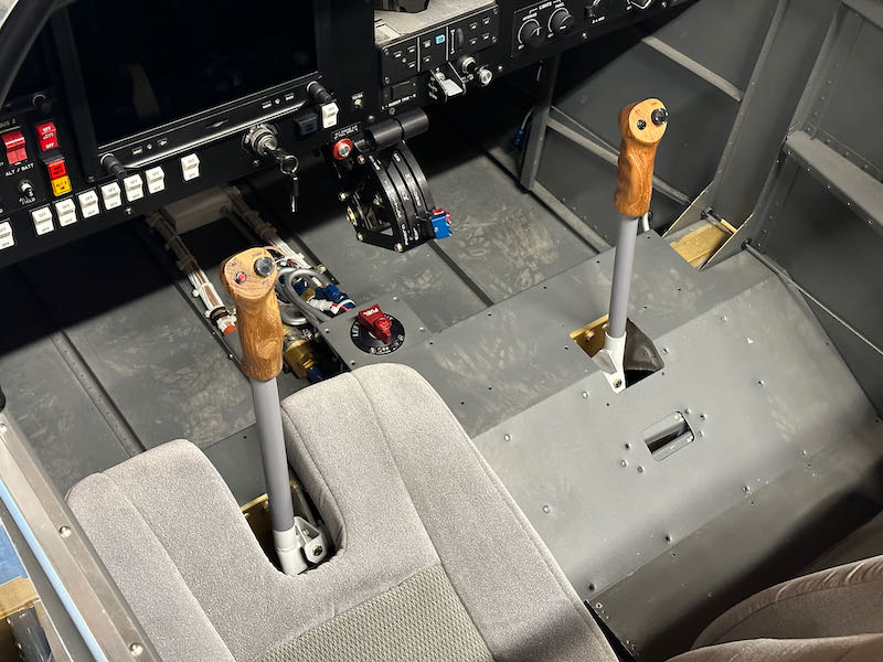
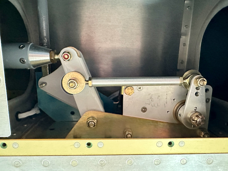
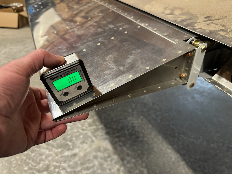
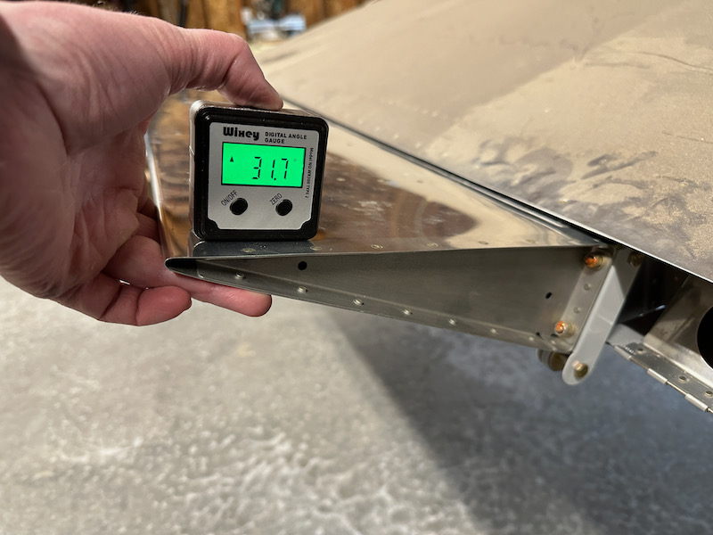
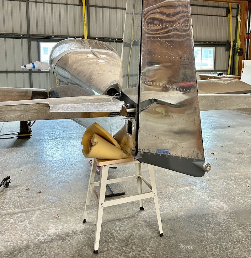
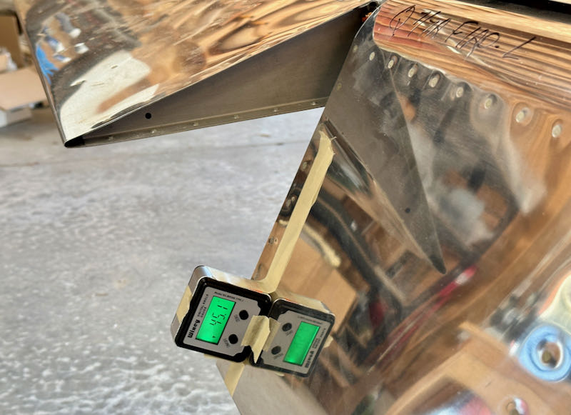
The plans list the flap travel limit as "40-45 degrees maximum", which is less than precise, but I don't think there is actually much adjustment possible with this mechanism – you just have to take what you get. In my case I am right at 45 degrees at full-down, which is acceptable. I haven't hooked up the flap positioning system yet, so this may be reduced slightly in the future.

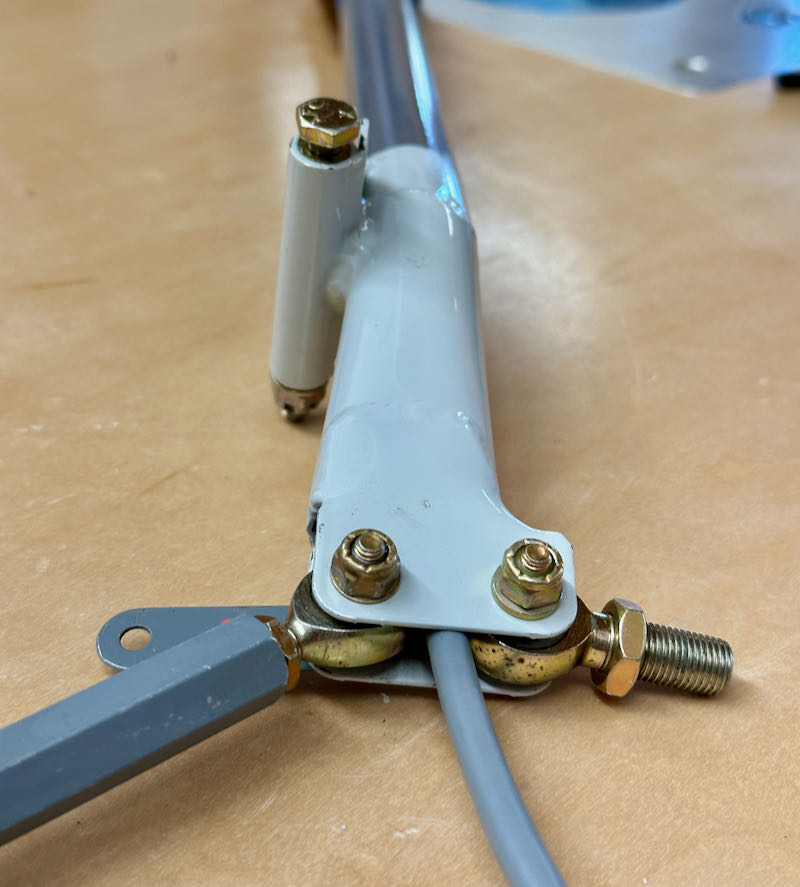
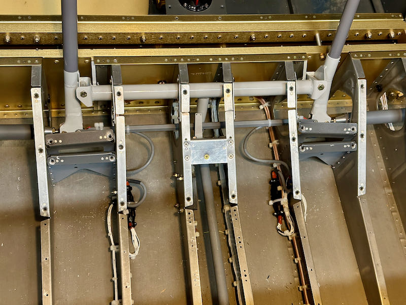
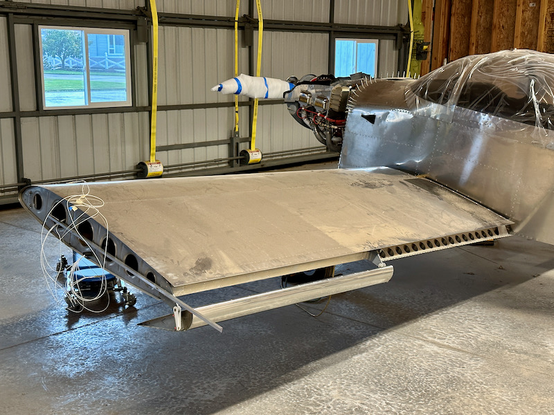
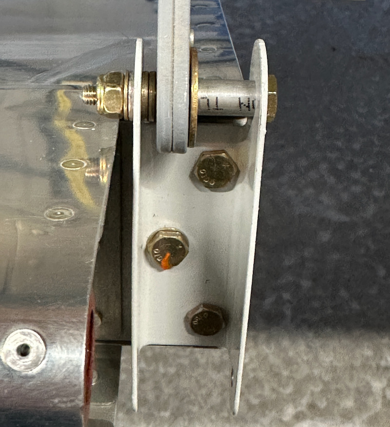
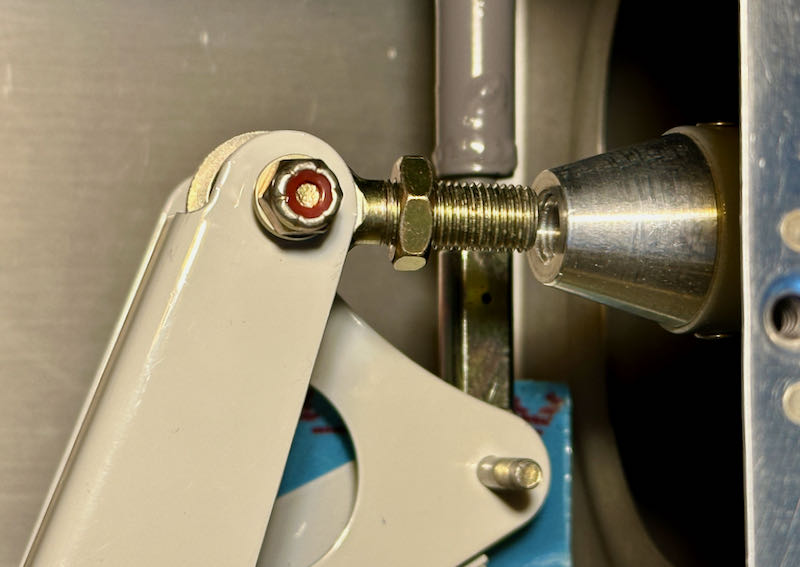
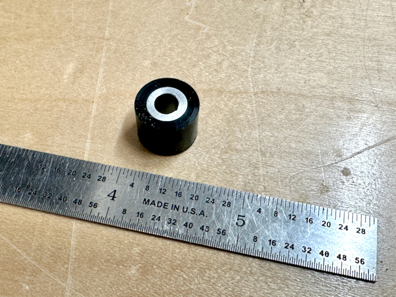
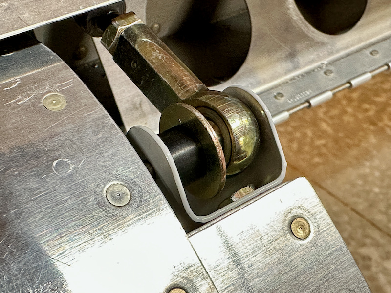
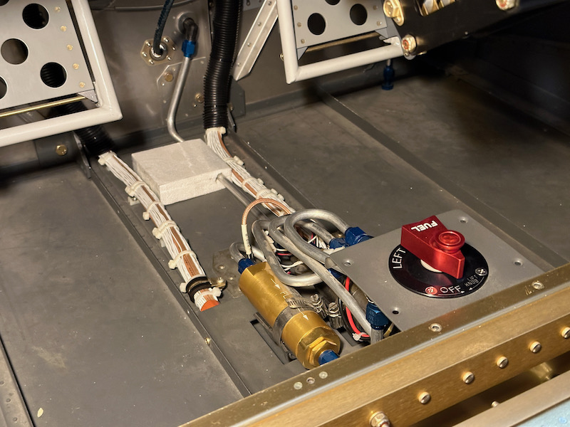
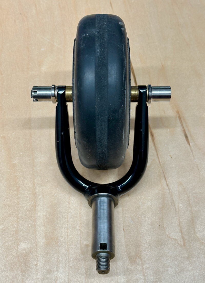
I don't want to install the flap mechanism permanently quite yet, and I don't want to damage the flaps while crawling in and out of the fuselage carrying tools, so I removed them from the wings and set them aside for now. While I have improved access to the lower rod end bearings, I removed and reinstalled them with lock washers and blue Loctite in accordance with the plans:

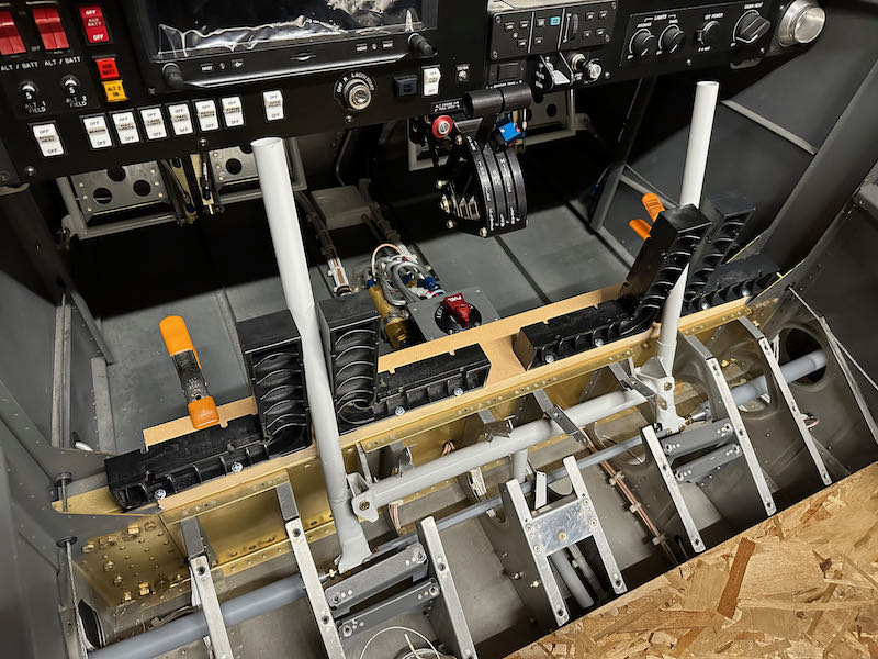
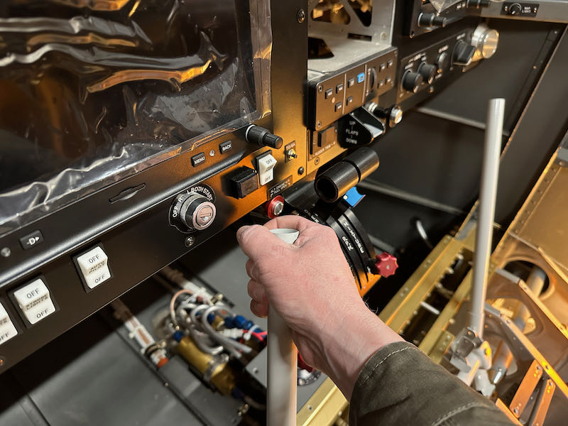
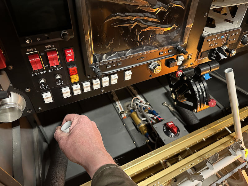
Still some work to be done before the flap system is truly finished, but it was neat to be able to hook up a battery and watch the flaps go up and down.

Stick grips & wiring

Saturday, May 27th, 2023

When we last saw the cockpit flight controls, I had the control stick geometry worked out but didn't have the stick grips installed yet:

The stick grips add some length, so the tubes have to be shortened to result in control sticks that are the correct length. I did this iteratively, to sneak up on the correct dimensions without making the sticks shorter than they need to be:

Frustratingly, with the sticks trimmed properly, the pilot stick grip hits the start key when moved to nearly full forward-right deflection. This was an unwelcome surprise:

This type of interference can't be allowed to exist, but I didn't want to shorten the sticks even further and affect the flight characteristics of the aircraft, so I was presented with a dilemma. Ironically, the part of the stick grip that contacts the key is the forward protrusion that used to house the start button – which is no longer required now that I've moved the starter control to the panel.

So, I figured the only workable solution was to have a new grip made. After a few emails with the manufacturer and the expenditure of a modest sum, I had a brand-new wood grip in hand. This one has the same functions as the old one, minus the unneeded extra button at the top, and consequently is smaller by just enough to allow the stick to achieve its full range of motion without hitting the start key. As long as I don't affect a big keychain for the airplane keys, this should work. Whew!

I had a local trophy shop engrave button labels on the new grip:

While I was waiting for the engraving job to get finished, I painted the visible parts of the stick tubes with my favorite grey enamel:

On to the wiring… instead of using standard aircraft wire here, I sourced some ultra-flexible cable intended for industrial robots. It is as bendy as a wet noodle, even though it has a total of nine conductors inside. It is also only 1/4" in diameter, which allows it to exit the stick tubes by passing down through the pushrod bearings:

This stuff is rated to withstand ten million flex cycles, so it ought to survive in my airplane just fine. I soldered the 24-gauge wires in the cables to the switches that live on the stick grips:

I'm using Otto P7 milspec switches for the autopilot disconnect and radio PTT buttons, and they have a very satisfying and expensive-feeling click action:

I didn't want to have to worry about these tiny wires getting pulled loose from the switches, so I fabricated some simple strain relief devices that live inside the stick tubes. Each one is nothing more than a close-fitting Delrin bushing and a zip tie that stops the cable from being pulled all the way out the bottom:

The flex cable assembly I bought had a pair of M12 connectors already installed. I had not encountered this type of connector before, and I'm glad I didn't have to solder or crimp them because they are really small. So small that they can fit inside the passenger stick tubes, which combined with the secure threaded and locking connection method makes them an ideal choice for the passenger side:

The mating connector lives inside the pivoting part of the passenger stick. The little zip-tie tail is there so I can fish it out if it falls down inside the socket:

Here's an overview of how I routed the cables from the sticks and connected them to the aircraft wiring. The flex cables are zip-tied to the F-665 pushrod, and a loop of cable is provided that's just slack enough to allow easy flexing but not so loose that the cable can chafe against the fuselage structure:

Here's another view showing how each side is arranged. The flex cable is secured at the stationary end by an adel clamp, and connects to the fuselage wiring via a 9-pin CPC connector:

With the control sticks completely installed at last, I reconnected the aileron trim springs:

I did a quick calibration of the aileron trim position sensor, resulting in one less red X on the screen:

As the final step, I attached the stick grips to the tubes using the manufacturer's recommended method of simply gluing them in place with clear silicone. To do this correctly, I had to install the seats and sit in the plane to judge the proper rotation angle while gluing the grips. Did I make airplane noises? I'll never tell…

Installed and rigged ailerons

Sunday, April 9th, 2023

I brought the ailerons down from the attic and cleaned off the worst of the dust – but not before being perplexed by the critter tracks I found. Let's hope that happened during the time I had them stored in a neighbor's hangar:

One of the steel hinge brackets had developed some rust, and though I could have cleaned it up and repainted it, I decided it was easier just to replace it with a new one:

With all that cleaned up, I proceeded to hang the ailerons on the wings:

I made the required hinge spacers on my little lathe, which is great for this kind of job:

This is what the hardware stack-up for the outboard hinge brackets looks like. (Note: many of these photos taken during the test-fitting process show loose fasteners and non-aviation hardware. I'll fix everything up properly when I'm done fiddling with things.)

I made a set of alignment tools out of hardware-store aluminum and bolted them to the tip rib. It helps to put some spacers between the angle and the rib (I used the lathe again) to prevent it from being bent by the outboard hinge bracket. That would throw off your aileron alignment and lead to problems later. You can also see here how I am holding the aileron in place with a strip of scrap aluminum and some cleco clamps:

This is an easy way to solidly hold the ailerons in the right orientation (tip aligned between the blue lines) while I work on other parts of the flight control system

This photo is looking up through the outboard access hole in the left wing. The W-818 pushrod runs from bottom to top on the left side, and the W-716 pushrod goes off to the left. Visible in back is the W-730 alignment jig holding the bellcrank in the right position. The idea here is that you use jigs to align the bellcrank and the aileron, then adjust the W-818 pushrod to connect them.

Although I fabricated my W-818 pushrods using the dimensions shown in the plans, they ended up slightly short. Judging from the many similar forum posts I've read, this is a common occurrence – it would be best to make them 3/16" or even 1/4" longer, material permitting. I solved the length problem here by switching the jam nuts to AN315s, which are 1/16" thicker than the default AN316s (a modification approved by Vans customer support). This ensures that no matter how the pushrod tries to unscrew itself, the worst-case rod end bearing will still have more than the minimum amount of thread engagement.

Inside the cockpit, I built a temporary jig to align the control sticks vertically, using a collection of woodworking squares which are screwed to a board clamped to the spar:

I maneuvered the W-716 (transverse) pushrods into the wings, adjusted them to fit between the control sticks and the aileron bellcranks, and then got a rude surprise. Although I built them exactly to the length specified in the plans, they are way too short, and will allow the rod end bearings to unthread themselves – an obviously unacceptable condition:

Judging from the many forum threads on this topic, this is another well-known plans error that has caught plenty of other builders just like it caught me. How incredibly aggravating. So now I'm on the hook for $100 worth of parts and the time required to build a new set of pushrods. At least nowadays I'm close enough to the factory to save on what would otherwise be the exorbitant cost of shipping long pieces of tubing. The new parts will be 7/16" longer than the plans dimensions:

These aluminum pushrods are trivial to build, but they end up taking a while due to all the priming required, especially in the winter. I flooded the interior of the tubes with 7220 spray primer and allowed them to dry for several days, then suspended them on strings and primed the outside:

Finally I riveted on the end caps, inserted the bearings with their jam nuts, and slid the new pushrods into the wings. The result is a perfect fit that can't possibly come undone. In retrospect I could have made these 3/8" longer rather than 7/16", but this will work fine. This photo shows that there are still plenty of threads engaged in the worst-case condition where the other end is screwed all the way in:

With the left and right ailerons finally connected together properly, I was able to fabricate the control stops. The plans call for a set of aluminum angle pieces riveted to the hinge brackets, but I wanted to try the popular method of using plastic bushings on the pushrod attachment bolts instead. I happened to have some black Delrin stock on the shelf, so I turned a pair of 1/2" diameter bushings with an aluminum spacer in the middle to handle compression:

This is what the aileron stops look like when installed – the black Delrin ought to be good for UV resistance:

It turns out that – for my airplane – the 1/2" diameter stops are an ideal size. To check the aileron travel I aligned the ailerons with the tip jigs and set my digital angle gauge to zero with the ailerons neutral:

The ailerons on both sides hit the up-stop just shy of the 32º maximum limit specified in the plans:

Similarly, the amount of down-travel is well past the minimum and just under the 17º maximum:

This also gives me my first chance to evaluate the total movement range of the control sticks inside the cockpit. Happily, neither stick comes close to hitting the throttle quadrant, which had been a concern:

Similarly, opposite aileron travel provides plenty of clearance between the sticks and anything nearby. I'll still have to trim these shorter to accommodate my stick grips, but it's good to know what I'm working with:

I haven't torqued all the fasteners yet, as I will probably have to remove the sticks at least one more time, but for now all the primary flight controls are hooked up and usable – a great milestone:

Fuel system plumbing

Monday, March 6th, 2023

Having finished all the electrical tasks in the lower-forward fuselage that I can conceive of, I should hopefully not have too much more crawling under the panel in my future, so there's no reason not to install the fuel plumbing for good. I retrieved the fuel pump/filter unit from storage, touched up the paint on the selector valve plate, and installed the whole assembly in the fuselage with screws:

Next I fabricated the remaining fuel lines that go between the wing tanks and the selector valve. I'm really glad I decided to make these in two pieces, with a bulkhead fitting in each F-783B cover support rib, because it would have been a nearly impossible task to fabricate these lines as a single piece. As it was it was still difficult – even though it's a pretty simple component, the lack of access and the fact that you have to bend and flare it in situ results in a fairly challenging job.

At each outboard side I used zip ties and a piece of rubber fuel hose to prevent the wiring bundle from chafing on the fuel line:

The plans call for a block of styrofoam to support the line that runs forward from the fuel pump to the firewall. I started with some craft foam and a hot-wire cutter:

I split the foam in half and cut out a groove for the fuel line. I like cutting foam with this tool, much less mess than traditional cutting tools – just try not to breathe the fumes.

Fuel line and foam support installed between pump and firewall – the foam block is held together with a strip of clear packing tape:

Out in the wing roots, I fabricated and installed the 1/4" vent lines that run from the tank to the fuselage, snaking around the tank attach bracket in the process. In the background you can see the 3/8" line that goes from the tank outlet into the fuselage:

As a final step in finishing the fuel system, I removed the plastic plugs from the bottom of tanks and installed the fuel quick drain valves:

It's kind of wild to think that, in theory, I could probably fill the tanks and start the engine almost any time I want. Well, a set of working brakes would probably be good first. Still, feels like progress.

Tailwheel upgrades & rigging

Wednesday, February 8th, 2023

I noticed the steel tailwheel spring was looking a bit ragged, so I pulled it off the fuselage for reconditioning prior to hooking up the tailwheel controls. With the wheel removed, I propped up the fuselage on a small work table with plenty of cushioning:

I scoured off the rust and old paint with a scotchbrite pad, and masked off the ends where necessary:

After a coat of primer and two coats of Rustoleum matte black, it's ready to go back to work:

While I had it all pulled apart, I decided to upgrade the wheel itself to a Flyboy Accessories unit with sealed ball bearings, so no more greasing will be required. I also picked up one of their extended axle kits, to give the towbar something more substantial to grab onto. Everything here is very nicely made:

With the help of a helpful forum thread, I put together a collection of hardware for the tailwheel steering controls that will allow me to omit the terrible wire clips, which tend to break and are generally a pain. I retained the stock steering chains and compression springs, but substituted better hardware in place of the clips.

In the center of this picture are some Maillon Rapide Links (part number 7350SF-1/8), a pair of AN42B-4A eye bolts, and some AN115-21 cable shackles. And at the bottom, another upgraded Flyboy Accessories part – a tailwheel steering arm with a lug for a tiedown rope.

Here's how it all looks when installed:

At the forward end, eye bolts and removable links replace the chain clips. These links are rated for a working load of 440 pounds, well in excess of what the chain itself will bear, and are Loctited closed.

At the back, the cable shackles connect the springs to the steering arm. I had to expand the inner dimension of the shackles slightly to fit over the arm, but they are malleable enough that this wasn't difficult.

I may need to adjust the tightness of the chains in the future – right now they are slightly slack when the weight is off the wheel – but this should be good enough for now.