I guess it's been long enough since I've updated my build log that people have started to worry. Thanks to those who have written to see if I am still alive… I swear I really have been working on the airplane! (although a bit sporadically) No pictures this time, as I have been having some computer and camera issues. Hopefully a nice big update soon. Stay tuned…
Archive for the ‘Misc’ Category
I am alive!
Sunday, August 18th, 2013Tool interlude
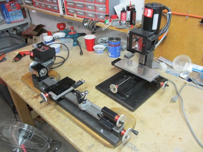
Monday, October 15th, 2012So yeah, it only took a few weeks for me to break down and buy a real milling machine. Like you didn't see that coming.
Actually I hadn't intended to get one right away, but I was unexpectedly lucky on eBay and got a very nice 12" Sherline mill to go with my 3.5×17" Sherline lathe. Judging from the few parts I've made with it so far, I can definitely see that a dedicated machine is a lot nicer and more capable than a lathe with a milling conversion attached.
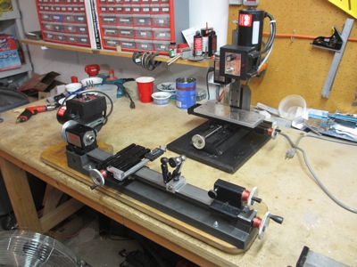
The mill seems to have hardly been used at all, but since it's at least fifteen years old and doesn't seem to have gotten much TLC during its life, I decided to strip it down to its component parts so I could clean and lubricate everything. I also replaced the AC cord and switch, and added a power indicator safety lamp as I did with the lathe. After putting everything together, the mill worked a lot smoother and with less backlash, so it was worth the effort.
Then while I was at it, I tore down the lathe to individual pieces too, and gave it the same tune-up treatment. Then for some reason I decided to really get crazy and add DRO scales to it too. That was more challenging than I initially thought, and took a couple weeks to really get sorted out, but it did give me a chance to use the new mill to make real parts. And now that the lathe is back together, it too works better and has digital readouts to boot. (I may add DRO to the mill as well, but if I do I'll almost certainly take the easy way out and buy a kit!)
Hopefully this will all come in handy for the airplane project. Don't worry, I haven't totally forgotten that I have one of those too.
Tool interlude
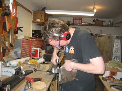
Sunday, April 3rd, 2011I went to fire up my drill press the other day, and absolutely nothing happened. I figured it must be the switch, which is a really low-quality plastic thing, but tested okay on my ohmmeter. So, I tore the thing apart trying to diagnose the problem.
Long story short, it actually was the switch – it was just making intermittent contact, and when I tested it the first time, it gave the false impression of being okay. But while I had the machine disassembled trying to pinpoint the problem, I managed to crack one of the cheaply-made pot-metal drive pulleys. Argh!
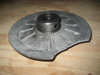
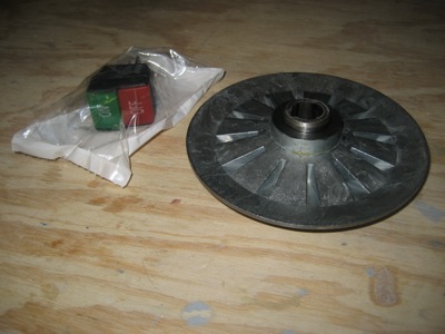
Since the cost for replacement parts was going to be about $50, and the whole drill press cost me less than $250 to begin with, I thought hard about just junking it – after salvaging the motor and chuck, of course – and buying a better-quality drill press to replace it. But after pondering it further, I decided I really want my next drill press to be a floor-stander, and I just don't have the space for one of those right now. So, fifty bucks and a few days later, I had a new switch and pulley in my mailbox.
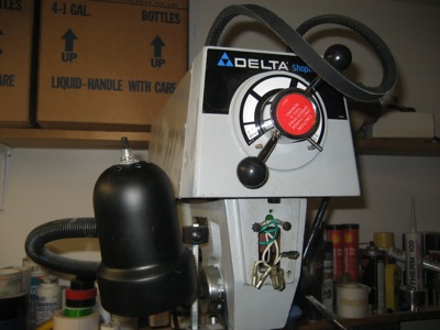
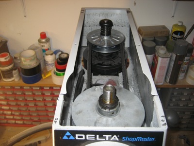
Here's what the drive mechanism on this model of drill press (Delta DP350) looks like. The pulleys on the motor and spindle are actually split into two halves, and control of the spindle speed is effected by varying the spacing between the pulley halves, thereby changing the effective pulley radius as seen by the belt. It's partially clever and partially hokey. On the one hand, this is the only low-end variable-speed drill press that doesn't require you to stop the machine and change belts to alter the spindle RPM; on the other hand, the low-end speed is too fast to use with a fly cutter, the special belt is expensive to replace, and the speed-change mechanism sometimes gets bound up. By the way, getting the collar and snap ring back onto the motor shaft while compressing that big spring was a fun chore.
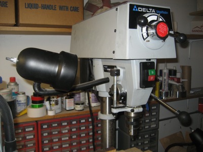
All back together and working again. One thing I will say for this drill press, it does have a very good depth stop (which I hardly ever use), the chuck is easy to adjust, and it generally seems to run true. It's just too bad about all the cheap internal parts. Hopefully by the time it breaks again, I'll have more space for a bigger and better model.
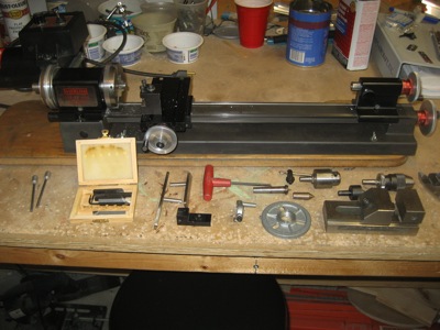
In other tool-related news, I bought a lathe! I've wanted to get one for a while, and when I saw that somebody in town was selling a Sherline 4400 on Craigslist, I couldn't resist.
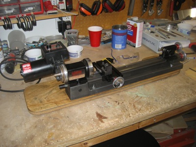
I got a pretty good deal, if I do say so myself. In addition to the basic lathe itself, I got a three-jaw chuck for the headstock, both a 1/4" Jacobs chuck and a 3/16" Albrecht chuck for the tailstock, a dead center, a live center, a lathe dog, a steady rest, a milling vise, and a collection of carbide cutting tools. And probably some other stuff that I don't even know how to recognize yet!
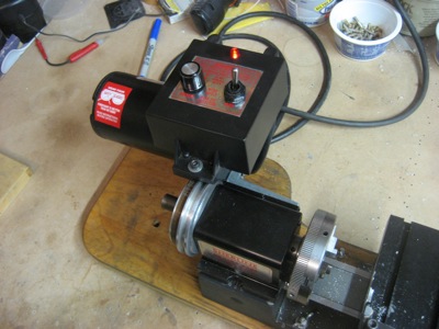
I have scant experience using a lathe, so this will be fun to learn on. I doubt I'll do anything fancy with it, but it should be great for making tubular spacers and the like. However, one thing I didn't like about the lathe when I got it was the fact that with speed knob dialed all the way down to zero, you don't have any indication that the power is switched on. I figured it would be bad to start messing with the chuck while accidentally leaving the lathe in a state where it could unexpectedly start turning, so I took apart the motor control box to see if I could rig up some kind of reminder lamp.
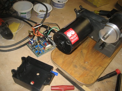
I bought a 120VAC neon bulb from Radio Shack, mounted it in the plastic cover, and connected it downstream from the power switch. I used high strength loctite to secure the mounting nut on the lamp, so it can't work its way loose and fall down onto the speed control board and cause a short.
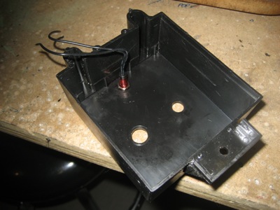
Voila, an obvious red light now reminds me to shut off the power before adjusting the lathe.
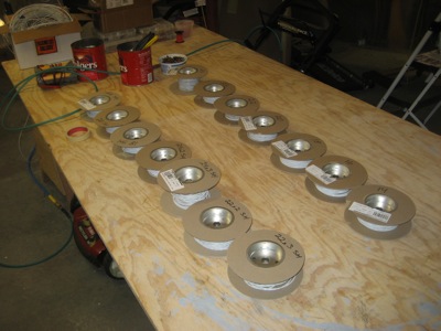
The lathe will get put to work soon to turn out some spacers for the oil cooler mounting bolts. Meanwhile, I have been working quite a bit on reinforcements to the baffles where the oil cooler will be attached, but I still have some work to do before I'm satisfied with the design.
Wiring and workshop cleanup
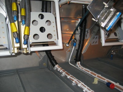
Saturday, May 15th, 2010I used split plastic conduit from the auto parts store to cover the exposed wiring that runs up the firewall. I have the goal of not having any exposed wires visible to the pilot or passenger, and this is an easy way to hide them. I thought about continuing the plastic stuff all the way to the spar, but it's too fat to allow the fuel pump assembly and center cabin cover to be installed.
That pretty much does it for the wiring that I'm able to finish at the present time. There are still plenty of loose ends (literally! ha-ha!) but I need to work on some other areas first. My garage was becoming highly cluttered after a whole winter of electrical work, so I spent the evening cleaning and putting away stuff that didn't need to be out anymore.
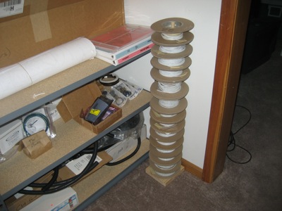
Hmm, what to do with all these spools of aircraft wire?
A hardwood dowel and a piece of scrap lumber make a handy wire stand!
It's shocking how many little plastic containers of loose hardware I have floating around the garage:
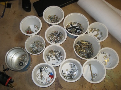
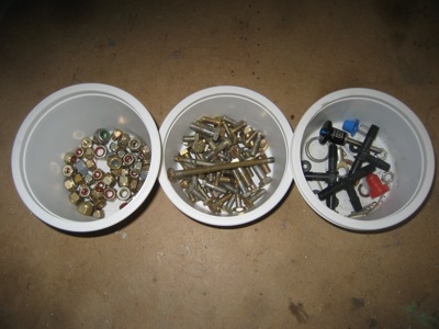
It took me a couple hours, but I reclaimed about three quarters of it all, and put each item back in its little drawer. I still have a bunch of AN nuts and bolts, which I am not returning to the general population since I don't want an old beat-up fastener to accidentally be used for something important. Plus there's a bucket of miscellaneous parts that don't have a home right now.
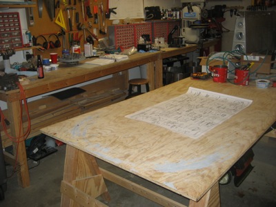
Plenty of room for the next project now! Although I'm sure I'll have it looking like a pig sty in no time.
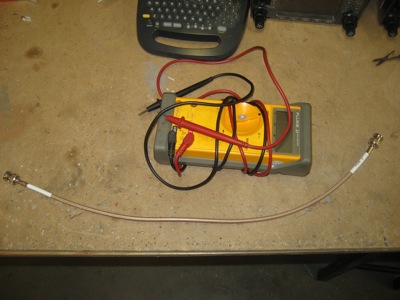
How to crimp BNC connectors
Monday, August 10th, 2009As I was making antenna cables, I thought it would be useful to show my method for crimping BNC connectors. The usual disclaimer applies: I am not an expert, I'm just showing you what I do.
I get my connectors from Aircraft Spruce, although you can find them just about anywhere. These particular ones are made by Amphenol and sell for about three bucks apiece.
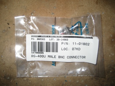
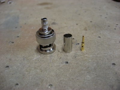
Here's what comes in the bag… connector body, ferrule, and center pin:
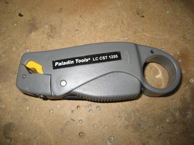
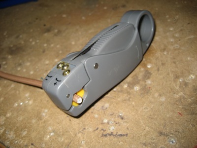
One of the secrets is to use the right kind of coax stripper. The tool I use has three spring-loaded blades in it (kind of like my razor, I suppose). If you see one at your local hardware emporium, be sure to check the model number – all the ones I found in the local stores were configured for television coax cable. For stripping the RG-58/RG-400 coax we use in airplanes, the model 1255 is the one you want. I couldn't find one locally so I had to mail-order it, but it was comparatively cheap.
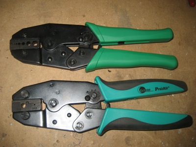
Since I'm a tool junkie, I experimented with different kinds of crimping tools. On the top is the "economy" racheting crimper sold by B&C for $40. On the bottom is an Eclipse frame with a set of RG-58/RG-400 BNC connector dies in it – cost for this setup is about $25 for the frame and $15 for the die, so it's basically a wash (prices are from Terminal Town where I bought mine). The dies on the economy tool are removable, and might actually be interchangeable with the Eclipse, but I haven't tried.
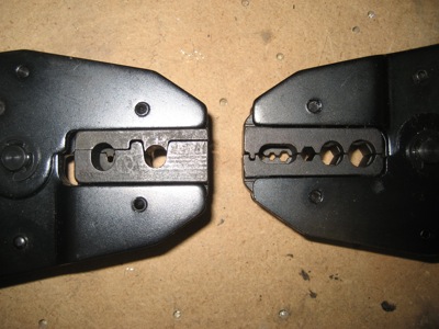
Here's a closeup of the crimp dies on both tools. On the left are the RG-58/RG-400 dies in the Eclipse tool, and you can see that there is just one crimp position for the pin and one for the ferrule. On the right is the economy tool, which can crimp multiple connector sizes. Either one works, although I find myself mostly using the Eclipse tool since I'm always crimping the same size of connector and it's impossible to get the pin in the wrong hole if you only have one choice. The other reason I prefer the Eclipse is that it makes a cleaner crimp on the pin… with the economy tool, the pin seems to get squashed flat a little more, so it's sometimes harder to get seated.
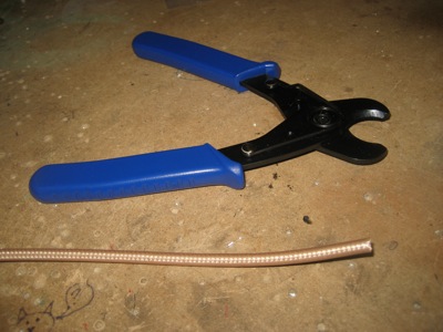
To cut the coax to length, be sure to use a real cable cutter, not a pair of dykes. The cable cutter has curved jaws that won't squash the coax insulation nearly as much, and it's cheap. These should be available wherever electrician's supplies are sold.
To strip the cable, clamp the stripper on the cut end using the illustration on the tool as a guide. It takes several practice runs to get the height-changing setscrews adjusted to give the proper depth of cut, so don't be afraid to use up a foot or two of coax getting your tool configured. To use the tool, use your finger to twirl it clockwise around the end of the cable (if oriented as it is in this picture) four times, then one turn counterclockwise.
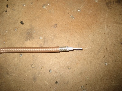
If the blades are set correctly, you'll end up with (from left to right) a shallow cut through the outer insulation, a deeper cut through the braided shield, and a third cut that goes through the inner insulation.
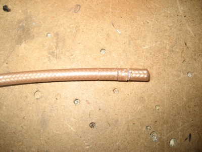
With gentle persuasion, the cut segments should come right off and leave you looking at the untouched material underneath the cut. Take a minute to closely examine the cable for stray shield strands that might float around and bridge your two conductors together. You can leave the center conductor slightly long, since you'll probably be trimming it a bit anyway.
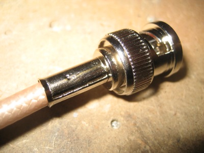
Slide the pin over the exposed center conductor. You want the base of the pin to be almost, but not quite, touching the white insulation. Trim the center conductor a bit at a time until it's the right length.
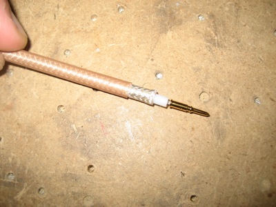
Squash the base of the pin with your crimper, and give it a tug to make sure it's secure.
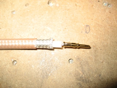
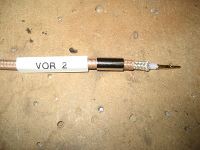
Now slide the ferrule over the cable. If you're going to label it, now is also the time to slide on your heatshrink label.
Push the connector body down over the end of the cable until you feel a click as the pin is seated. The knurled bit on the back will dig under the braided shield. If you encounter strong resistance, can't get the pin all the way in, or don't feel the click, the most likely problem is that the crimper has deformed your pin enough to make it hang up in the connector body (see above).
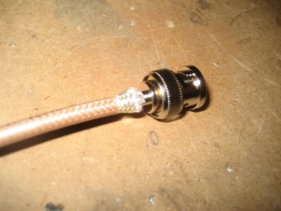
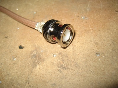
When properly seated, the end of the pin should be flush with the end of the plastic insert inside the connector:
Without unseating the center pin, slide the ferrule down over the exposed shield. With the neato coax stripper I use, you should find that the shield has been trimmed to the perfect length and you don't have any stray shield strands poking out.
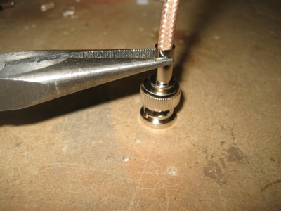
Now crimp the ferrule, and you're done.
I like to do a quick continuity check just to make sure the center pin isn't shorted to the shield anywhere. Antennas don't work very well with a shorted cable.