Archive for August, 2008

Power wires

Wednesday, August 27th, 2008

I received the terminal I needed to finish up the main bus power wire. Since the wire is captive in the panel, I had to crimp it in situ. I used a big wooden clamp as a sort of makeshift vise to hold the crimper while I bore down on the wrench.

The #6 wire for bus 1 and the #10 wire for bus 2 are both terminated and covered by rubber boots. Also, I love my shrink tube label maker.

Bus 2's power wire parallels the bigger wire for bus 1. They will eventually be tie-wrapped together (along with probably a bunch of other wires) but for now are loosely held together with masking tape.

Through the firewall and down the engine mount to the 30 amp current limiter:

One wire at a time…

Empennage fairing fitting

Sunday, August 24th, 2008

This morning I woke up early and flew a rental spamcan up to Falls City in Nebraska, taking advantage of the unseasonably cool (for August) morning to get a little daylight between me and the ground. Falls City has always held a certain special fascination for me; the first airplane I owned came with a Falls City Aero Service keychain, and though I never got around to making the short flight, I always wondered just what sort of a place it was. Turns out it's exactly like you'd think: a medium-sized runway, some old tin hangars, and a flock of agplanes. Nice morning though.

Later on, I got out the empennage fairing and spent some time cleaning it up. I used heat and pressure to reshape the areas that didn't fit so great – by clamping down a small section of fiberglass with wood blocks and duct tape, heating up the surrounding area with my heat gun, then letting it cool down, I iteratively got it to fit pretty well. Then I trimmed back the edges, countersunk the holes for tinnerman washers, and installed it with #6 screws to see how it looked.

Not bad really. I may have some additional shaping to do along the top edge, but that's all cosmetic. Overall, I'm pretty happy with how it turned out. There are some gaps of a 32nd or two here and there, but at Oshkosh this year I saw some that looked like they'd been put on with a hammer… quarter inch gaps, even. So, I think mine looks pretty good.

Since I was already sweaty and gross from cutting and sanding fiberglass, I decided to make it a trifecta by mowing the lawn and then going for a nine mile bike ride. Now it is, as they say in the old country, die Miller-Zeit.

Took panel to machine shop

Monday, August 18th, 2008

Today I took my uncut panel and electronic drawings to the machine shop near where I work. They're going to first cut me a test panel out of clear acrylic so I can double check the fit of all the various instruments and switches. If that goes well, I'll then have them push the button on the CNC machine again and turn me out a (hopefully) perfect panel.

Started running wires

Sunday, August 17th, 2008

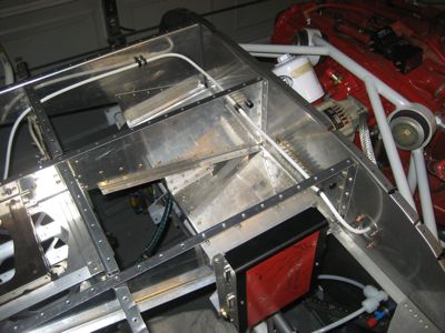
I ran the 6 AWG wire that provides power to the main bus up from the current limiter, through the firewall, and across the cockpit to the main fuse block. This wire is clamped to the engine mount in three places, since it will form the spine of a whole bundle of wires that will run up and down the starboard side of the engine compartment.

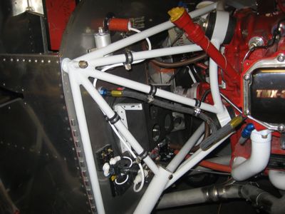
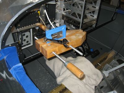
This was the first outing for my latest tool, a pair of vise grip pliers modified to hold adel clamps in position while you get the bolt in. Normally these are a giant pain to install, but the tool helped. I did find that I still needed to use the safety wire trick sometimes, which in conjunction with the pliers made installing adel clamps a relative breeze.

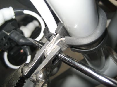
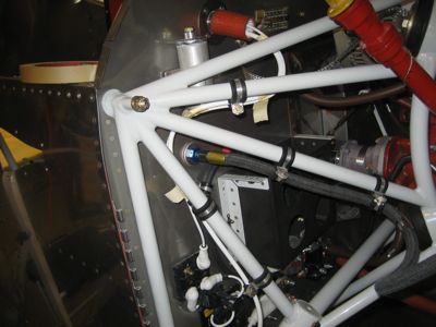
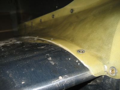
Closeup view of the bottom end of the wire, where it attaches to the current limiter:

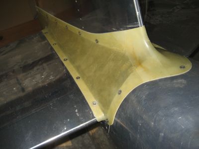
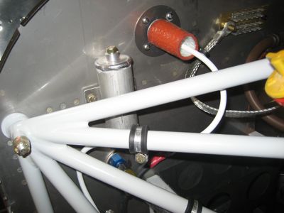
Up the side of the engine mount and through the firewall passthrough:

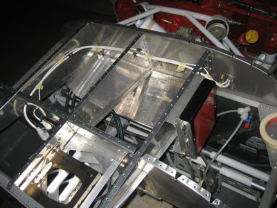
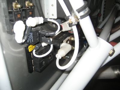
Inside the cockpit it takes a turn, goes through the subpanel ribs via a pair of snap bushings, takes another 90 degree bend into an adel clamp, and penetrates the subpanel through another snap bushing.

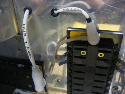
From there it dips down, and will eventually attach to the post on the main fuse block as soon as I can scare up the proper ring terminal for the end.

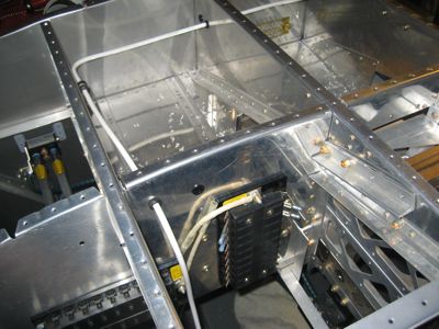
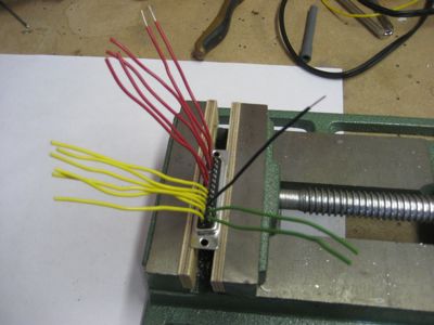
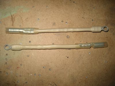
I also made some fusible links, which are visible in the picture above. These will be used to protect the wires that go from the two fuse blocks to the diode on the other side of the subpanel. They're just lengths of normal tefzel wire, four sizes down from the wire being protected (the wires to the diode are 10 gauge, so these links are 14 gauge). Over the wire is a fireproof silicone sleeve, in case the fusible link is called upon to do its thing. The idea here is that you use a fusible link anywhere you can't normally use a regular fuse or circuit breaker, but where you still want protection in the unlikely event of a short circuit.

Not a lot of work on the plane lately due to too much time spent at the office, too much heat in the garage, and too much Mary away on the road (which you'd think would theoretically leave more time to work on the plane, but in reality I seem to always find myself at work instead). But this was a pretty good weekend.

Assembled annunciator controller

Sunday, August 17th, 2008

I got my annunciator controller board back from ExpressPCB. Their board layout software is pretty terrible, but the finished product looks okay. If you look closely, you might be able to spot the switch mounting pad I had to grind off because it was too close to the processor reset line. A real board layout tool would have caught that with a design rule check, but of course the crappy free software doesn't have one. Oh well – that turned out to be the only mistake I made (and believe me, nobody is more surprised than I am).

I grabbed a spare D-sub connector and made a little test harness to power the board and test its inputs and outputs.

In keeping with the time-honored traditions of testing out a new PCB design, I soldered the minimal components needed to get the processor running (power supply, oscillator, and the microcontroller itself) and hooked it up to the debugger to see if I could make it blink an LED.

It blinks! This means that the microcontroller is alive and can be programmed. It doesn't look like much, but if a board can get to this stage, then almost everything is working.

Here's the finished product, with voltage dividers, filters, and driver transistors in place. It will be able to sense up to 8 inputs and control up to 6 annunciator lights, depending on how I choose to write the finished firmware. The end goal here is to be able to do a few things with warning lights that are just slightly more sophisticated than simply hooking up a lamp.