Archive for the ‘Baffles’ Category

Ignition wire seals

Sunday, February 19th, 2012

To pass spark plug leads through the baffles, you use these two-piece plastic wire seals, which require an oddly shaped hole. The bit of aluminum in this photo is a drill template I made out of scrap.

Ideally I would have cut the required holes in the baffles earlier so I didn't have to mess around with removing and reinstalling them, but my ideas about ignition systems have been evolving recently so it can't be helped. I'll discuss that further in a future update. Here I've used one of the existing rivet holes to locate the upper fastener for the wire seal in the the left rear baffle, per the plans:

#10 screws will be used to attach the plastic seal to the baffle, after the wires have been passed through and the two halves snapped together:

Testing the wire routing… it looks like with a bit of securing, I should be able to keep the wires well away from the fuel injection lines:

Same deal for the right rear baffle. I chose to file the holes to an oblong shape instead of a figure-eight. Not sure why, since it doesn't really matter.

While I had the right rear baffle off the engine, I took the opportunity to fill a little gap towards the bottom with red RTV:

I had a complaint recently that I haven't posted any beer pictures in a while. So here's today's selection, a nice pint of Guinness – it's too cold in the garage for anything else.

Baffle tension rods

Sunday, February 5th, 2012

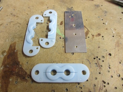
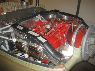
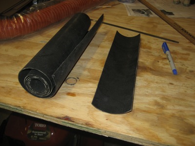
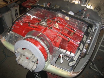
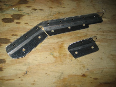
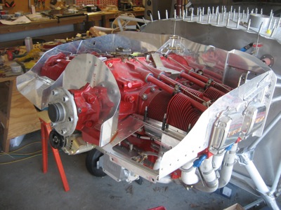
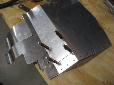
The forward and rear parts of the baffles are tied together underneath the engine cylinders with steel tension rods. These pull the baffles down and around to keep them in contact with the cooling fins, which forces air to go through them and do useful work cooling the engine. You make these out of raw stock, bending as required to clear various protuberances that stick out of the engine.

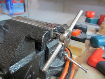
Threading the stainless rods is kind of a chore, but relatively ordinary all the same. Forward a half-turn, back a quarter-turn, repeat until done, and use plenty of cutting fluid.

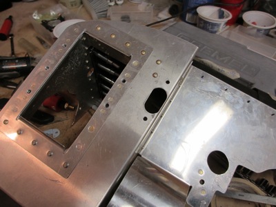
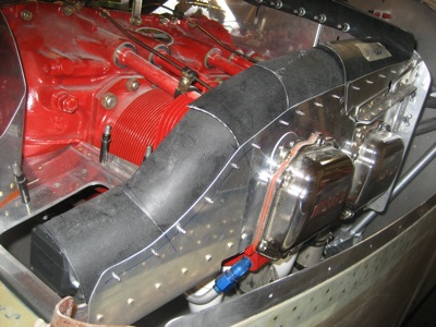
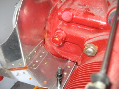
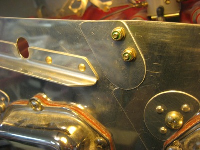
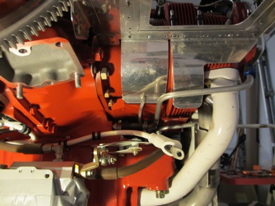
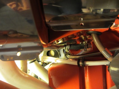
Here's a view of the general area where this is going on. You can see where the left inboard tension rod is in place, and the outboard rod has yet to be fitted.

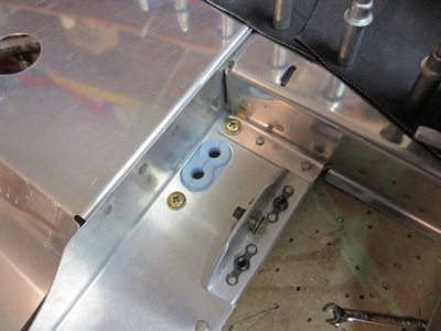
A closeup of the left inboard tension rod being fitted. The hardware is only temporary – this will use all-metal locknuts when it's installed for good. The portion of the rod between the forward and aft attach tabs is covered with nylon tubing in order to keep it from chafing on the bottom of the cylinder.

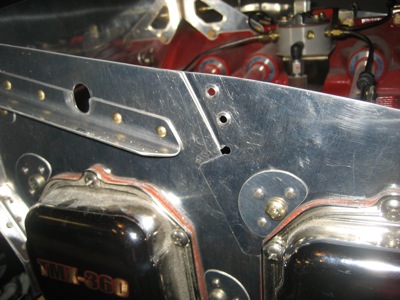
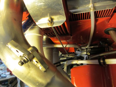
Here's the inboard rod on the right side of the engine being fitted. You can see how it's bent to fit through the available space:

It's hard to see, let alone get a photo of, but the hose clamp near the center of the image was in the way of the right outboard tension rod. I managed to remove the clamp, shorten the band, and reinstall it in a friendlier orientation.

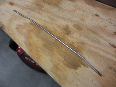
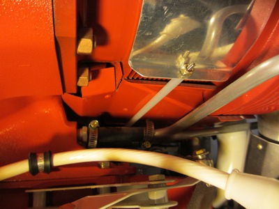
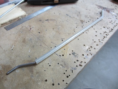
Test-fitting the right outboard tension rod. This has quite a significant Z-bend at either end, although from this angle it's hard to notice.

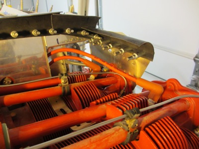
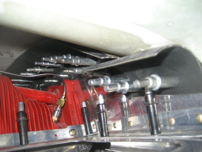
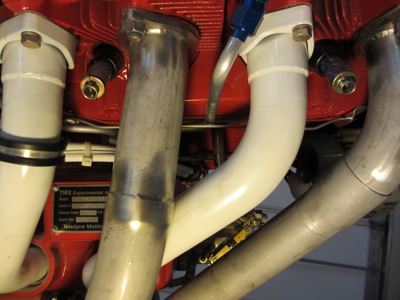
A view from the side, peeking through the exhaust pipes and intake tubes:

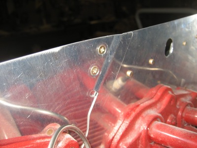
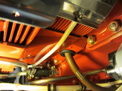
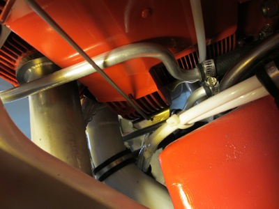
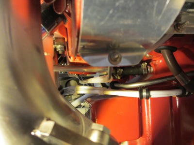
You want to ensure that there's sufficient separation between the steel rod and the aluminum oil return line to keep one from chafing through the other and letting out all your engine oil:

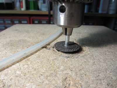
I wanted to put nylon tubing over the outboard rods as well, but they're bent too sharply to let it fit past the bends. So instead I split the tubing along its length, by cranking my drill press spindle down almost to the table, and carefully running the plastic tube against a cutting wheel. (while wearing heavy gloves, of course!)

Perfect fit:

Here you can see how the outboard rod has to dive down to clear the oil tube, then turn back up again at the far end. But one thing I found worrying about this arrangement was the fact that there was nothing to keep the bent rod in the correct orientation required to prevent it from rubbing on the oil tube.

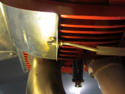
I solved this by using an extra nut and washer at one end, to clamp the rod firmly to the attach tab. Now it can't rotate on its own. At the other end, I kept the default single nut so that the rod can still slip through the hole in the other attach tab, to handle the cylinders shaking around independently while the engine is running.

Various things have been going on to prevent me from working on the airplane recently, but hopefully I'll be able to do a lot more work going forward. Feels good to be back to fabricating stuff out of metal.

Started baffle seals

Sunday, November 27th, 2011

I started fabricating and fitting the rubber strips that seal the baffles to the cowl. These allow the engine to move independently from the cowl, while preventing the incoming air from escaping past the baffles. In effect, the whole top of the engine becomes a plenum chamber with the top cowl as the lid, and the cooing air is forced down through the engine cylinders.

Before I got the tools out, I did a bunch of thread-reading on VAF, then went to the airport and looked under the cowl of as many RV's as I could find (five). It turned out that every one of airplanes I encountered had its baffle seals done in a different way, but it was interesting to see which ones fit well and which ones had leaks. In the end I came away with some good ideas that I'll try to put into practice.

In places where the baffles are curved, I used multiple overlapping strips to avoid wrinkles that could cause leaks. Each one overlaps its neighbor in such a way that the incoming airflow will tend to flatten it against the baffles and top cowl – sort of like bird feathers. The fastener holes are 3/8" from the edge of the baffles, spaced approximately every 1 1/2". Eventually the rubber seals will be riveted to the metal baffles with large-head blind rivets.

Since the seal material (rubberized fabric) comes rolled up, it has a natural curve to it. I took advantage of this by cutting parallel to the axis of curvature and orienting each piece of material so it naturally wants to bend inwards.

A leather punch is about the best way to put the fastener holes in the rubber strips. The rubber doesn't drill well with a normal twist bit, but the punch makes a clean hole without tearing.

Looking into the cowl inlet during a test-fit. I purposefully left the rubber strips overly long so I could trim them to fit later. The forward end especially will need some work, since there will also be a separate set of rubber strips attached to the lower cowl.

I managed to fit rubber seals to all the outboard and aft cylinder baffles before I got tired. The prop hub and flywheel will have to come off again in order to do the crankcase baffle seals anyway, so this is a good stopping point.

Finished baffle riveting

Sunday, November 13th, 2011

After trimming the baffles to their final shape, I finished riveting together all the parts that I had been leaving clecoed together for fitting purposes. First I made some doublers out of scrap to reinforce the outboard corner of the #3 cylinder baffle:

Here's what it looks like riveted together:

Another view. I'm not sure if reinforcement is strictly necessary here, but it was easy enough to do and adds almost no weight.

Here's the previously-seen #1 cylinder baffle, newly riveted to the starboard side crankcase baffle.

Closeup view of the joint… flush rivets towards the front where the rubber seal material will go:

And now the #2 cylinder baffle, also riveted to its corresponding crankcase baffle. I later used RTV to fill those visible gaps where the parts come together.

A view of the #2 cylinder baffle from the aft side. The angle reinforcement piece has almost no rivets through it, since it will primarily be secured by the screws that hold the air filter retaining ring.

All the baffles are now riveted together permanently, and back on the engine temporarily:

It's a bit hard to see in a photo, but there are substantial gaps between the forward baffles and the nose of the crankcase that will have to be caulked up when I put them on for good. You can also see some of the RTV previously mentioned.

The plans tell you to rivet little tabs to the forward cylinder baffles where they overlap the aft ones, to make a sort of expansion joint. I wanted these to be removable without drilling out rivets, so I sized the holes for #6 screws instead.

Screw heads are flush on the inside to accommodate the rubber seals:

I cut the tabs slightly oversize so they would seal up the tooling hole that's visible in the previous photo:

One small step at a time…

Heater duct cover plate

Sunday, November 13th, 2011

The #3 cylinder baffle, as supplied from the factory, has a big round hole cut in it. You're supposed to attach a hose flange here and connect a scat hose to pick up air for the cabin heat… problem is, that only works for a vertical induction engine, and mine has horizontal induction. So I had to fabricate a cover plate to make the hole go away.

I put a bead of RTV between the baffle and the cover plate to keep air from leaking past. I'll have to wait till I buy the heat muff to figure exactly where I'm going to relocate the heater air supply.