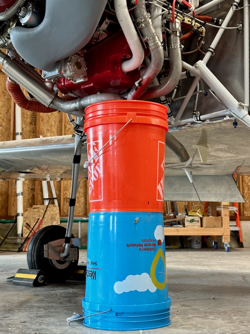
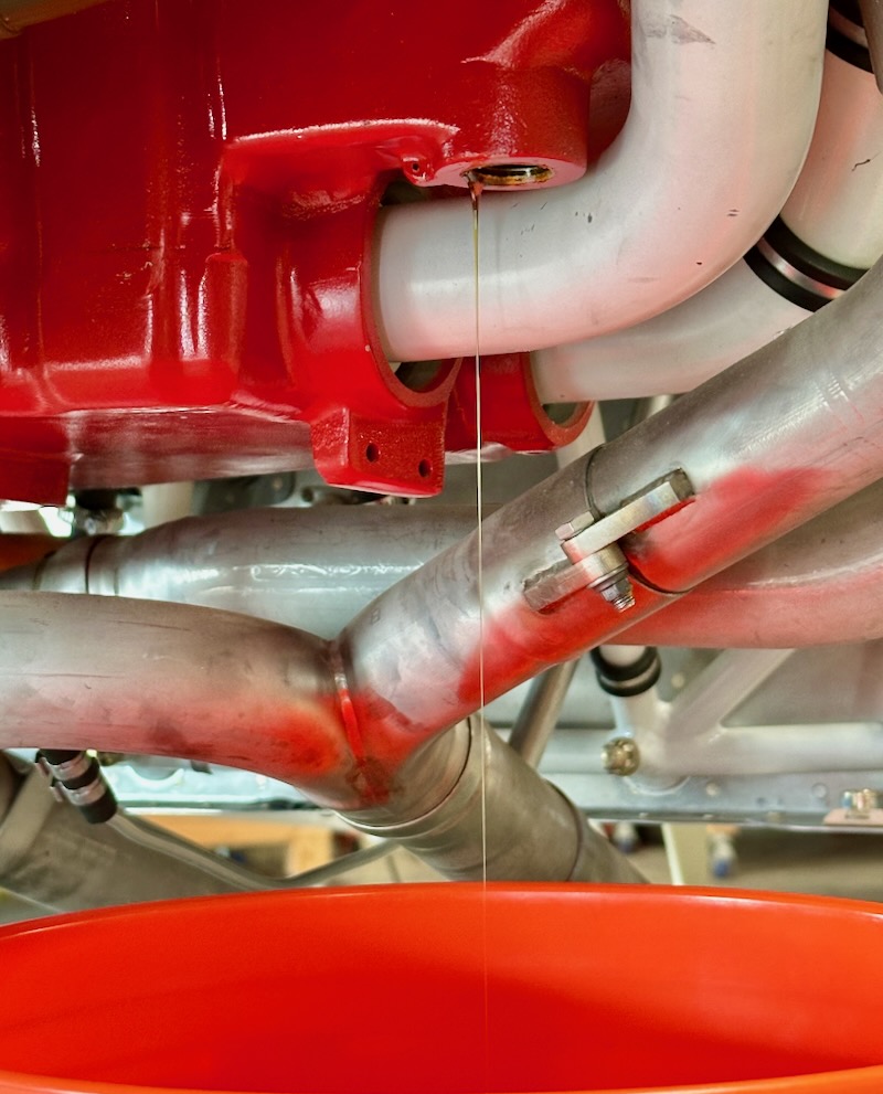
I leveled the airplane, unscrewed the more accessible of the two symmetrical oil drain plugs, and drained as much of the ancient oil out of the sump as I could:
I'm sure I didn't get it all, as it doesn't drain all that well when cold, but whatever is left over shouldn't hurt anything.
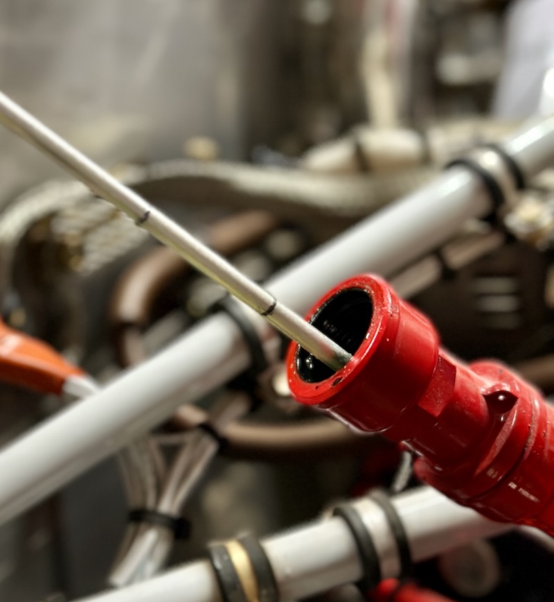
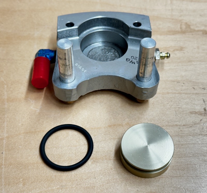
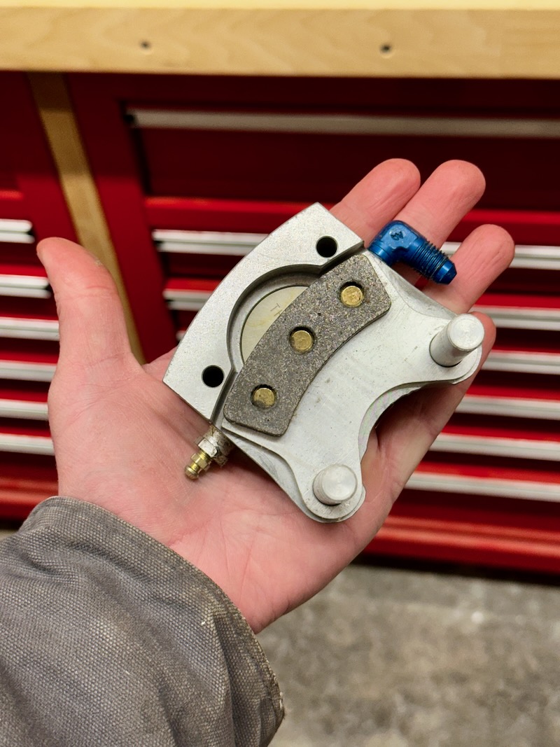
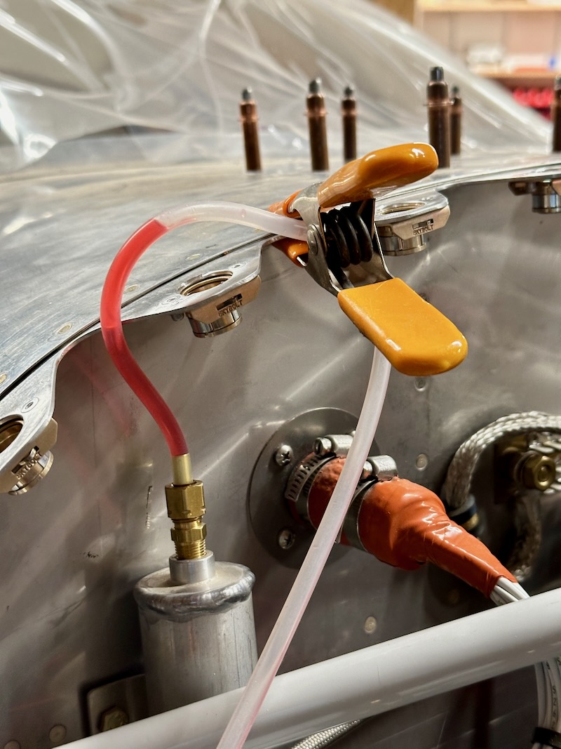
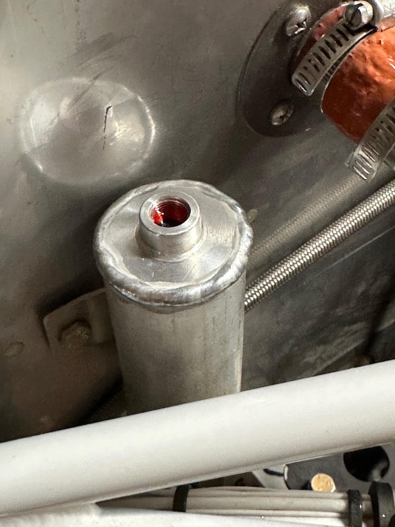
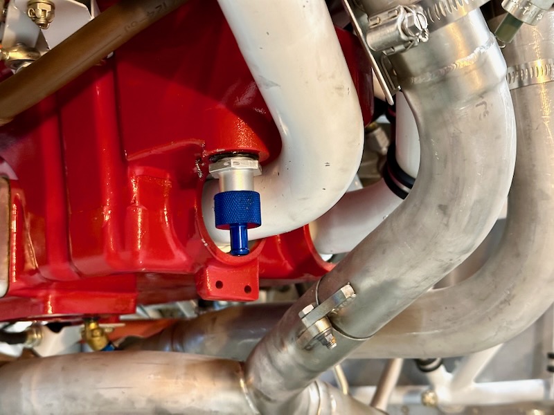
I took the opportunity to install a Saf-Air quick drain valve, which will make the next oil change easier:
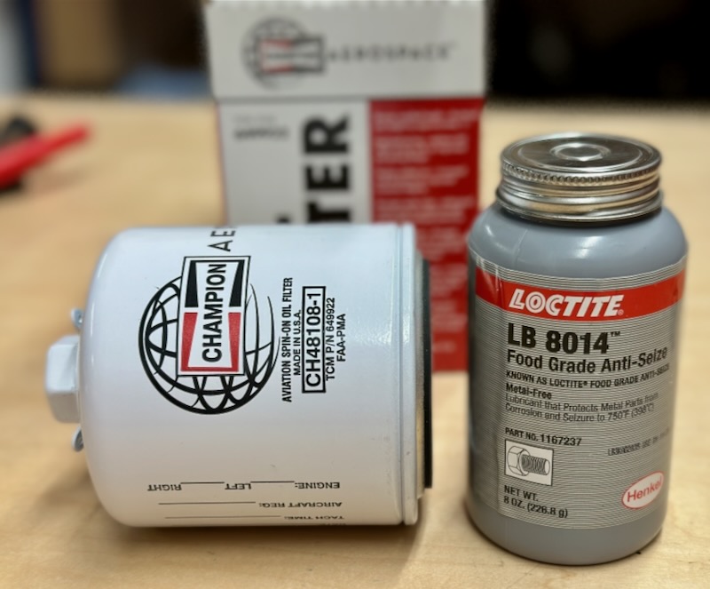
I bought some fresh oil filters, plus the specific food-grade anti-seize Lycoming wants you to use on the threads. I guess they specify this so you don't get copper in the oil system, but it's funny to think about eating off the oil filter adapter.
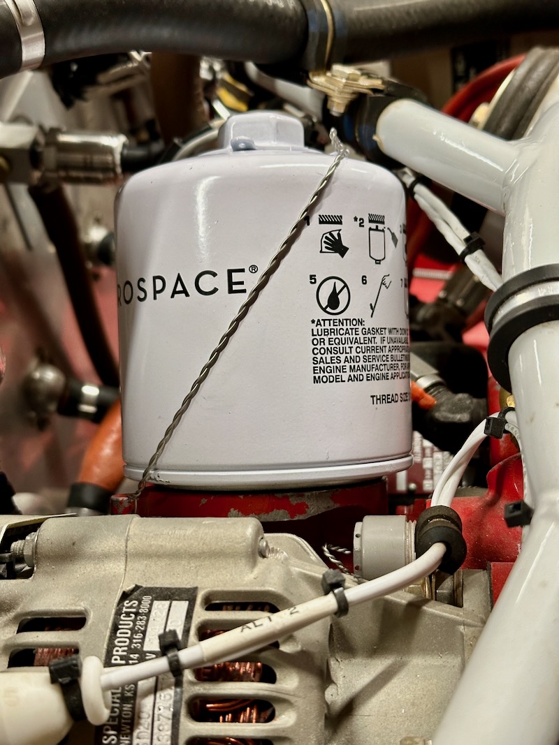
Oil filter torqued and safetied:
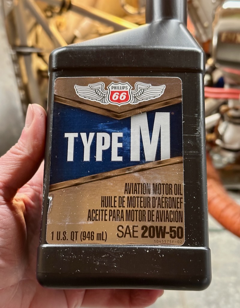
For the first fifty hours – kind of a weird thing to think about! – I'll be using 20W-50 non-AD mineral oil, per the Lycoming guidance. I put in eight quarts, which is more than I'd usually run in an IO-360, but some of that is going to disappear into the various oil passages pretty quickly.
The oil dipstick comes un-marked, so you have to make your own oil level markings. For now, I provisionally marked every two quarts with a sharpie and a tiny nick from a file at each successive level, just so I can monitor the initial oil consumption. After the first proper oil change with warm oil, I'll have a better opportunity to properly calibrate the dipstick.