Archive for December, 2006

Installed cowl hinges on firewall

Sunday, December 10th, 2006

The next milestone in this little odyssey is to get the engine mount installed. But I decided to first install the hinges that will attach the lower part of the cowling to the firewall. Others have reported problems getting enough access to set the rivets once the engine mount is in place, so I figured why not save myself some trouble and avoid that problem entirely.

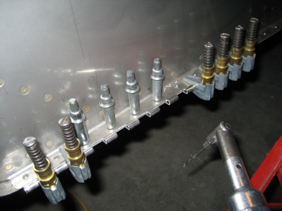
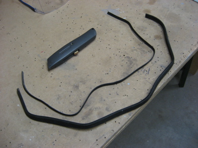
The plans don't actually tell you how long to make each of the four hinge pieces that are required, but I was able to puzzle it out by looking at the rivet callouts on drawing 28. I clamped each piece to the outside face of the firewall flange and back drilled using the prepunched and pre-dimpled holes as a gude.

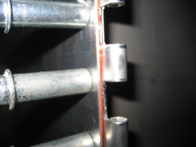
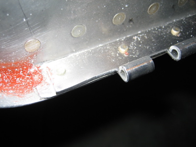
Before I put in the rivets that attach the fuselage side skins to the firewall, I squeezed a bead of red RTV in the gap between the two surfaces, to help seal the cabin from exhaust fumes and smoke (hopefully not applicable). The lower flange seems to have been sealed with proseal by the quickbuild factory, but I don't think proseal is especially heat-resistant so I went with the high-temp RTV.

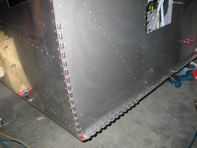
Here the hinges have been riveted to the side and bottom firewall flanges.

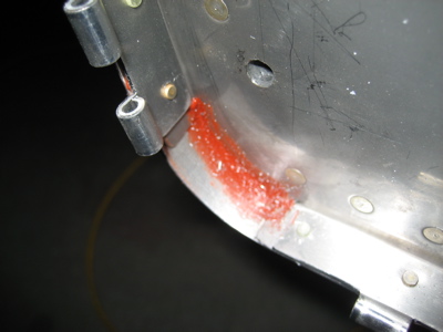
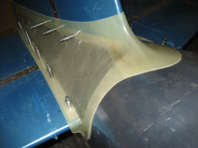
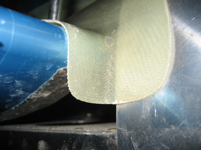
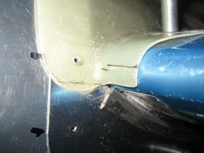
At both of the bottom corners of the firewall, I laid down a fairly thick fillet of RTV to cover over a gap that was about 1/16" on both sides. A lot of nasty fumes could have gotten in through here. Also, if I was smart I would have waited until the glue was dry before doing stuff that made drill chips, but oh well.

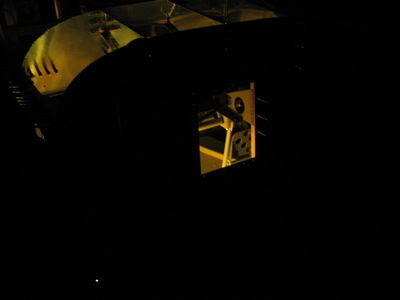
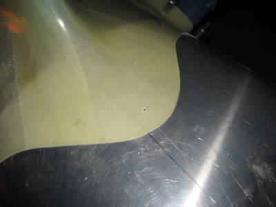
I turned off the shop lights and put my work light inside the fuselage to look for unsealed gaps. The only light coming from the sides and bottom of the firewall was through the engine mount bolt holes, so I'd say this part of the firewall is sealed.

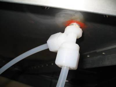
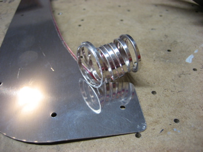
While I had the RTV uncorked I put down another fillet to seal around the hole in the firewall where the brake fluid reservoir pokes through.

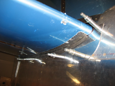
Of course as soon as I started trial-fitting the engine mount, I discovered that the taildragger gear leg sockets interefered with the outermost hinge eyelets, so I had to cut off part of my newly installed hinges. Oh well, it's easier to make them shorter than longer.

The engine mount is attached to the fuselage with six 3/8" bolts. In four of those locations, there are 1/4" pilot holes already drilled by the quickbuilders. I think what I'll do in order to get a perfect fit is grab some steel tubing from Airparts and make up some 3/8" OD, 1/4" ID bushings. That should let me bolt the mount to the firewall through two or more of the undersized pilot holes, the drill and ream each hole up to final size without worrying about how to clamp the mount to the fuselage.

Working on empennage fairing

Saturday, December 9th, 2006

I got the empennage fairing out again and continued playing around with it. Here it's clecoed to the tail using the holes I'd previously made:

There's a ton of extra material to be trimmed off where the fairing wraps around the leading edge of the horizontal stabilizer. Then the gap underneath the stabilizer is closed by aluminum cover plates. You're sort of left to your own devices to figure out exactly how to make the front part of this come out looking nice.

I had to trim a fair amount off of the F-794 cover plates to make them fit. Maybe I can sell the scraps as aluminum curly fries.

The kit comes with some rubber weather strip type of stuff, which you have to trim down.

Here's one of the cover plates with the rubber strip on it. It's clecoed to the fuselage through some rivet holes in the longeron and bulkhead that I had to drill out. I wish the quickbuilders had left those holes open, because it's somewhat difficult to get under there and drill them out with the stabilizer attached, but oh well. It's hard to get the rubber strip to go completely around the curved are in the front, so I sized the cover plate piece to almost touch the stabilizer in that area instead.

Here I've trimmed and sanded away the excess fiberglass of the fairing at the forward corners (ignore the sharpie lines, I was using them to test various ideas). As you can see, there's only a very small area that's not covered by fiberglass, aluminum, or rubber. It's on the bottom of the airplane so you'll never see it. Good enough.

I also finished the cutout for the elevator horns, and sanded the aft edges of the fairing to be even with the edges of the vertical and horizontal stabilizer skins.

Because the front part of the vertical stabilizer is offset to the left (i.e. right rudder) the center of the fairing doesn't sit on the centerline of the fuselage. I eyeballed this spot for a screw and nutplate on the forward lip.

Interestingly, in the spots where the fairing attach screws go into the fuselage longerons, the plans call for you to just tap the hole in the longeron instead of installing nutplates. I used to have problems with the screws backing out in this area on my old RV, so I'm wondering if it would be worth the extra trouble to use nutplates back here (because nutplates have a self-locking feature to secure the screws). May need to call Van's to make sure the extra rivet holes in the longeron wouldn't be a strength problem. At first glance it looks like there would be plenty of room between the nutplate rivets and the next rivets over.

I live

Wednesday, December 6th, 2006

Beware, I live! Heh.

No updates recently because I haven't done any work on the plane – I've been either busy or sick. But while I was bedridden I ordered a bunch of stuff, and everything except my Van's order has arrived. Now I have an ELT, a master solenoid, a firewall ground block, a battery charger, a bunch of fiberglass supplies, and other stuff:

The long tubelike things shown above are bolts of fiberglass cloth of various weights.

Of course the Van's order isn't here because Van's has the slowest shipping ever, but then you probably knew that.