I've been struggling for more than a week to figure out exactly how to correctly hook up the engine control cables. Rather than fill up the whole internet with a play-by-play of the various things I tried, I'll just show you the end results.
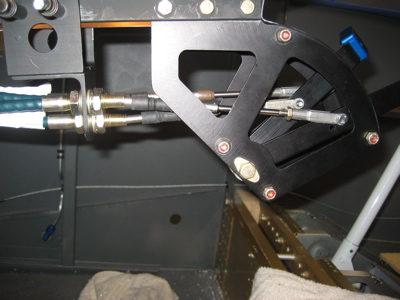
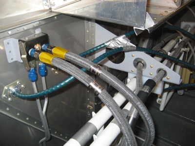
Here are the cables mounted to the cable bracket, with clevises installed. You can sort of see that I had to drill new holes in the throttle and mixture levers in order to get sufficient travel at the other end. To do this I had to take apart the throttle quadrant, which was straightforward but annoying.
The cables fan out from the bracket in various directions. I may use adel clamps to tie the throttle and prop cables together (approximately where the piece of masking tape is) just to keep them from chafing.
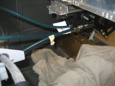
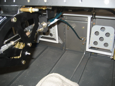
The prop and mixture cable arc rather gracefully (if you ask me) over the top of the rudder pedal brace, and go through the firewall on either side of the parking brake plumbing. The previous careful measuring and use of custom-length cables paid off here, as these two cables manage to go where they need to go without getting hung up on anything. I will eventually replace the experimental duct tape with a pair of adel clamps, mostly to keep the prop cable well clear of the brake hoses.
The throttle cable is basically a straight shot from the quadrant down to the lower center of the firewall. I ended up using my 48" cable here after all, as the 49.5" one I'd ordered from Van's was a bit too long. I may end up returning that one, or I may just keep it around for whatever.
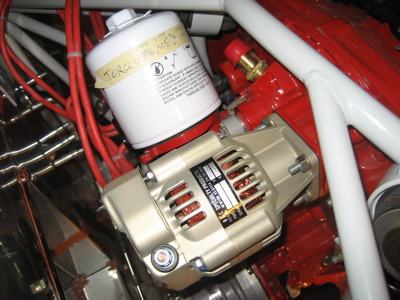
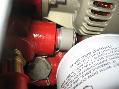
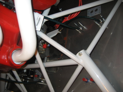
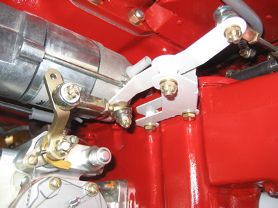
The prop cable makes a hard right turn after passing through the firewall eyeball, and crosses over the mixture cable to reach the prop governor cable bracket. Meanwhile, the mixture cable continues forward to its own cable bracket on the top of the oil sump. The throttle cable is visible down below.
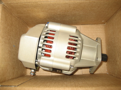
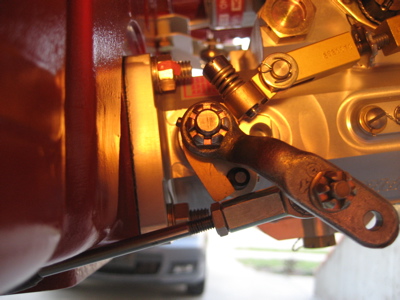
I had to use a joggled mixture control arm in order to get it to clear my Skytec NL inline starter. I think you could use a straight arm if you had a Skytec LS or PM model, but the NL is quite a bit longer than either of those two.
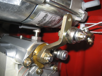
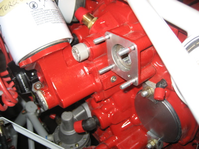
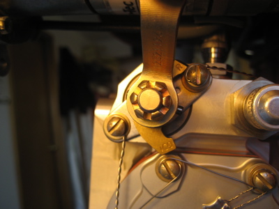
Here's how the mixture bellcrank works. The mixture cable connects to the arm on the right side of the photo, and the bellcrank provides the necessary offset to reach the mixture arm and also reverses the direction of movement. You'll note that I had to drill a second hole much closer to the mixture control arm's pivot point… this is necessary because the limited amount of travel available at the quadrant end requires a shorter mixture control arm in order to get full travel at the servo.
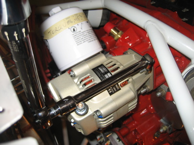
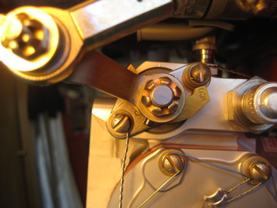
Here's photographic proof that the mixture can reach the full rich stop:
…as well as the idle cutoff stop:
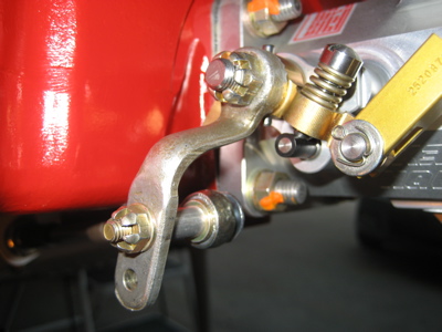
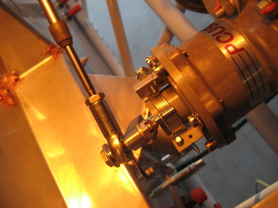
Despite the apparent complexity of the mixture bellcrank, I didn't really have much difficulty getting the mixture control working properly. The throttle was actually the hardest one, because of the very limited clearances that exist with the forward-facing fuel injection servo (if you have one, you'll see what I mean). I ended up having Mattituck send me another joggled control arm that I could use for the throttle, and shortened it as I did with the mixture arm. Here it's shown at the idle stop. Not visible is how close the rod end bearing comes to the bottom of the oil sump when the throttle is all the way back like this… it's close, but there is still just barely enough room.
With the throttle all the way to the wide open stop, the cable shaft almost touches the bottom of the oil sump as well. Moving the attachment point of the rod end bearing farther away from the pivot point is the obvious remedy, of course, but then the throttle quadrant wouldn't give me enough travel to go all the way from idle to full throttle. This would not be a problem if I was using standard plunger-style engine controls, but with the throttle quadrant it's an additional huge headache that I wasn't really expecting. I spent a week wrestling with this before arriving at this solution, and it just barely works (but it does work!). From what I've seen, I think that this wouldn't be so much of an issue with a vertical induction setup, but the combination of a throttle quadrant and forward induction is extremely tricky to get right.
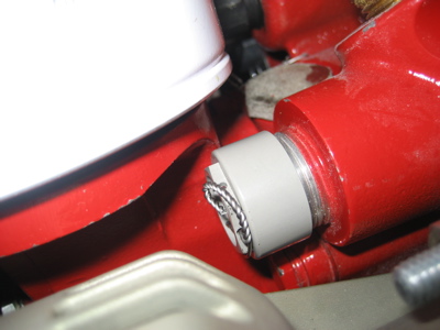
Here's the prop governor cable at the fine pitch (full RPM) stop. It's actually spring-loaded to return to this position – I guess so that a broken cable will tend to return to the full RPM setting, which would be preferable to the opposite behavior in an emergency.

Once again, the throttle quadrant limits the amount of travel I can get out of the prop cable – I can only get the lever to move about halfway from the fine pitch stop to the coarse pitch stop. The plans actually mention that this might happen, but they don't provide a recommended minimum amount of travel. Just to be safe, I fired off an email to the manufacturer of my prop governor, to determine a) if this is an acceptable amount of travel, and if not; b) if a shorter control arm is available.
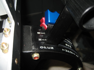
I set things up so that at the most forward position (full throttle, high RPM, rich mixture), all three of the engine control levers are almost, but not quite, at the end of their travel. There is a gap of about 1/16" at the top of each lever's travel, which provides a certain amount of "springback" to let you know that you've hit the actual stop on the engine instead of just hitting the limit of the lever's travel within the throttle quadrant. This is a good practice that I picked up from one or more RV elders. Obviously, in a situation like mine where the throttle quadrant is the thing that gives you the most problems in getting full travel out of your controls, you have to be very careful about balancing the goal of getting the correct amount of positive springback against the desire to get as much travel out of your quadrant as you can. Tricky.
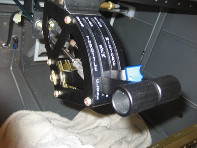
At the full-aft position, the throttle and mixture levers are not quite at their limit of travel, so I know from the springback effect that the throttle and mixture are hitting the correct stops on the engine. The prop lever does hit the quadrant housing and limits the amount of prop control movement, as discussed above.
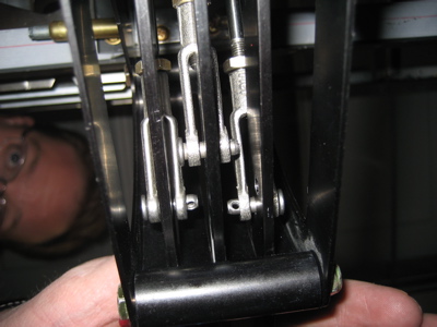
Here's a shot from the floor of the airplane, looking up into the bottom of the throttle quadrant. It's not quite as bad as the perspective in this photo makes it look, but there is still not a lot of clearance between adjacent clevises within the quadrant. I'm going to have to get creative to keep the engine control levers from jamming against one another.
Note: All the preceding photos were taken during development, before any hardware was installed for good – hence the absence of cotter pins. When I decide that the engine controls are really, really done, only then will I go to the trouble of installing all the correct fasteners.
Update: For those who've emailed asking about cable lengths, the final sizes I picked were 48", 51", and 52.5". Obviously these lengths are only applicable to my particular airplane, but if you are using a DJM quadrant with an IO-360-M1B and Bendix/Silverhawk injection these will be a good place to start.