Author Archive

Wiring

Monday, October 27th, 2008

I made a cable to connect my bench power supply to the airplane, where the battery would normally be hooked up. This will let me test the wiring as I go. I also bought the totally sweet mechanic's creeper that's visible in the background. I've always wanted a flimsy excuse to buy one of those.

Mary, ever a good sport, agreed to crawl into the fuselage to help me rivet some tie wrap anchors in place.

…while I was on the creeper below, pulling rivets:

We put in two rows of plastic tie wrap anchors between the firewall and spar. They are attached to the floor with blind rivets that are flush on the exterior skin. Here you can see I've started to run a few wires back to the cargo bay area.

More tie wrap anchors are riveted to the sides of the center tunnel between the forward and aft spars. These will be used to keep the wire bundles away from the elevator pushrod. Some of these were kind of tricky to rivet in, but I'm glad I went to the extra effort instead of cheating by using the self-adhesive kind. I just don't trust them to not eventually come unglued.

So far, most of the wires I've run through the center tunnel go to the aux battery.

I'm still playing with the exact configuration of the aux battery charging circuit.

Planning the routing of wire bundles and then actually running the wires is a delicate, fiddly, and complicated business – so of course I love it. But I'll admit that it doesn't make for very exciting photographs. I will try to post interesting things here, but don't expect a picture of every wire! Once I get farther along I'll post an updated schematic of the airplane, for those who are really into this kind of thing.

Temporarily securing wire bundles

Sunday, October 19th, 2008

I've been stringing wires around behind the panel, and experimenting with ways to keep the wire bundles organized as I build them up one wire at a time. A lot of folks do this with tie wraps, but that seems like it could be very wasteful – especially if you're freaky about keeping your wires neat like I am. Every time you need to add another wire to a bundle, you have to clip off the old tie wraps, throw them away, and install another set.

I tried masking tape instead of tie wraps, but I was almost immediately annoyed by how fiddly it was to peel the tape off the wire bundles. So, time for a new idea.

I've had this box, which contains several yards of self-adhesive velcro, laying around my shop for years. I cut out some small pieces and stuck them to each other, so I ended up with a handful of velcro strips with hooks on one side and loops on the other.

These velcro strips can be temporarily wrapped around a wire bundle to keep it from unravelling, and of course being velcro they come off without fuss.

Another way to temporarily keep wire bundles tidy is to use twist ties. I made a bunch out of three-inch lengths of some solid-core copper wire I had laying around. The red insulation will help me remember to eventually replace them with actual tie wraps when I'm finished running wires.

As you can see, this helps keep the wires together in neat bundles (but I'm not wasting a pile of tie wraps).

You can even run the wire ties through one of those little nylon tie wrap anchors I love so much:

I've found that I tend to use both methods in conjunction – velcro strips to hold things when I'm pulling a new wire and I just need an extra hand, and twist ties when I'm through adding a wire to a bundle.

Wiring

Sunday, October 19th, 2008

Yes, I am alive… I was laid up and unable to work on the airplane for several days, thanks to my lovely wife who works with sick people and sometimes brings her work home with her. Ahem. Anyway, I have been running a few wires here and there, which is both interesting and challenging – however, it unfortunately does not always lend itself to exciting and dynamic photographs for one's world-wide-web-log. But here are a few pictures nonetheless.

I soldered wire leads to a 5W, 5Ω resistor, then mummified it with heatshrink tubing per this method – the better to keep the resistor leads from breaking off thanks to vibration. I probably didn't really need to label it, but I wanted to see if my heatshrink label printer could do an omega symbol.

I used a clamp to affix the resistor to one of the subpanel ribs, and also bolted in a power diode. These components are part of the circuit that trickle-charges the aux battery.

I ran some wires to the bus master switches, which should soon provide me the ability to turn the various buses on and off. See the next post for an explanation of the red twist-tie looking things.

Here's another view of the festivities. I put in a few snap bushings here and there to allow wire bundles to be routed to various places.

Flap switch guard

Sunday, September 28th, 2008

I've been flying a DA20 lately, and in addition to the various things I like about how it handles, I particularly like the little guard thingy that Diamond puts on the DA20's flap switch. I decided to make one for my airplane too, starting with a chunk of 1"x2"x1/16" extruded aluminum.

I drilled a hole for the switch in the exact center of the piece I cut, then sawed off one side of the rectangle. The flap switch handle fits perfectly between the two sides.

After much cutting and filing, I ended up with a halfway decent looking switch guard:

Here's how it looks with the switch handle removed. I drilled and tapped holes for a pair of 4-40 screws; one into the spacer behind the panel, and the other one into the panel frame. Between the screws and the switch mounting nut and keyway washer, the switch guard isn't going anywhere.

A small hole on one side admits a hex wrench, so I can tighten the set screw that keeps the switch handle from spinning off the shaft.

See, it works – you can easily actuate the switch with your finger:

…but foreign objects flying around the cockpit can't accidentally make the flaps go down. Also, please recycle.

Also, Mary was in town this weekend, so here's the usual photo of her looking cute:

Started panel for real

Saturday, September 20th, 2008

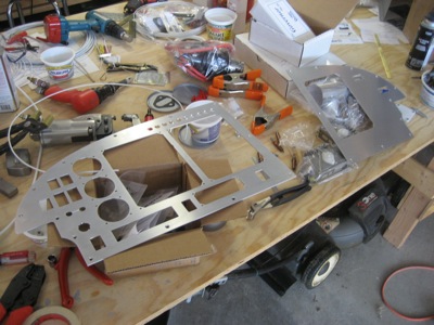
A month after I submitted the initial set of drawing files, I got the finished panel back from the machine shop. The total bill was… well, I don't even want to write down what I had to pay, but suffice to say it was about quadruple what I was expecting. It turned out pretty nice, but there's no way I would use that same shop again. I would have been better off sending the design to one of the several places that specialize in CNC cutting of airplane panels. Anyway, let's forget that ugliness and keep moving forward.

I fit the various switches, breakers, etc. to the pilot's side panel. Everything fit very well after a little bit of work with a file.

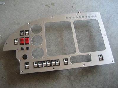
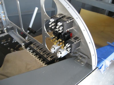
A view of the other side:

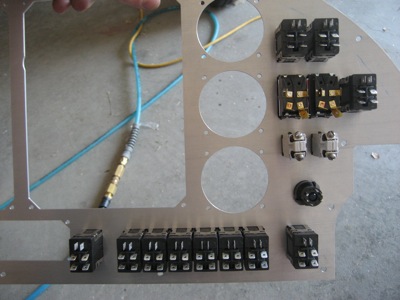
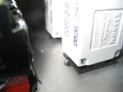
Closeup of the alternator circuit breakers… you can see where the machine shop guy made a booboo. The CNC machine was programmed to drag the cutting tool across the surface of the panel, making a nice little trench. Luckily this is not a big deal, since I was already planning to put an engraved placard over the top of this area. If it had been anywhere else, I'd have been pissed.

I used a 1/8" drill to make some little divots on the back side of the panel, for the circuit breaker keyway washers to catch on.

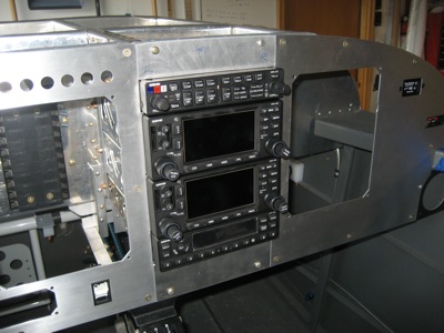
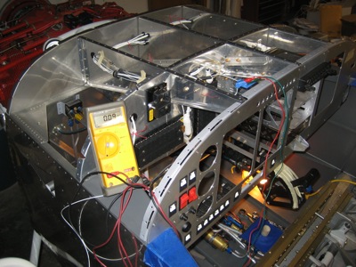
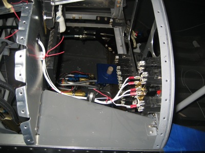
Passenger-side panel installed in the fuselage:

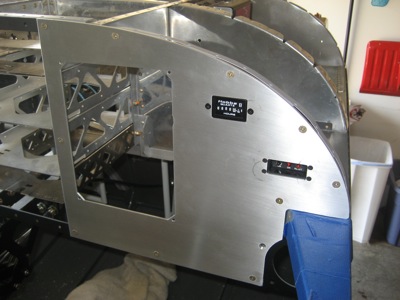
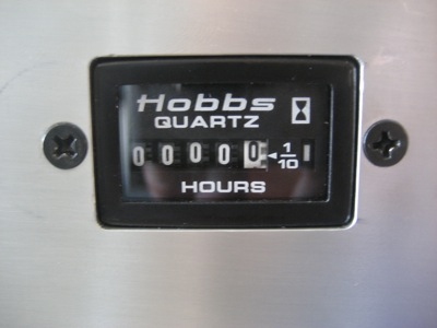
Zero hours on the Hobbs!

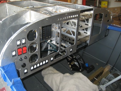
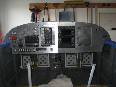
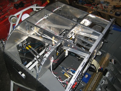
Pilot-side panel installed, and looking pretty sweet if I do say so myself. By the way, my plan is to get everything wired up, drill holes for miscellaneous other stuff like parking brake and heat valve cables, and then take it all apart for painting or powder coating (haven't yet decided which).

Same thing from the other side. The canopy deck intrudes a bit on the available behind-panel space, forcing you to think three-dimensionally when locating your panel components. Luckily I got it right, and nothing runs into anything else.

I temporarily installed the radios, and cut some 0.090" filler plates to cover the unused area at the top and bottom of the radio stack.

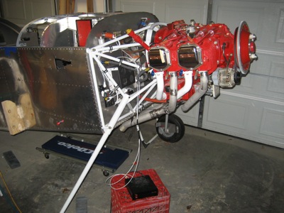
This is the money shot:

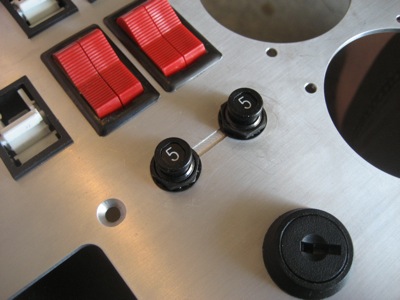
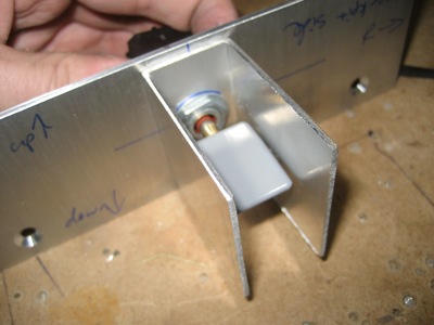
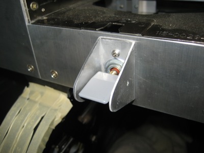
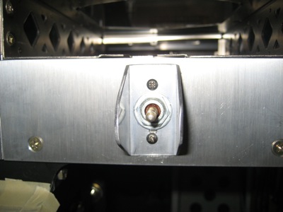
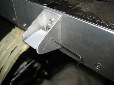
At Oshkosh I good a good deal on this fancy flap switch. It has a little flap-shaped piece of aluminum for a handle, which is a cool touch.

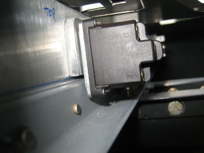
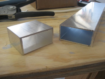
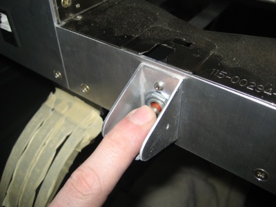
In order to get the switch body to clear the panel frame, I had to make (I hesitate to say "machine" since my tools are fairly primitive) this spacer out of 3/16" stock. Right now it's just captured by the switch, but I may end up riveting it to the panel just because.

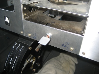
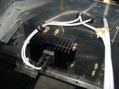
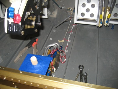
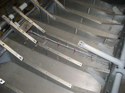
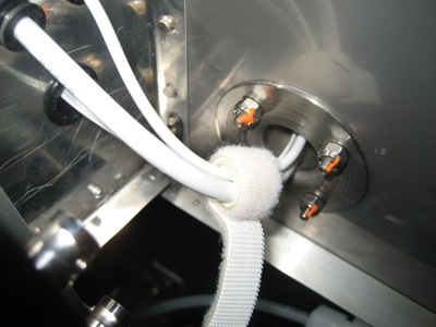
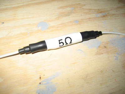
I never finished wiring the two buses together at the bus tie diode, so I finished that tonight. This is a power diode with a hefty heatsink, which provides an alternate power path from bus 1 to bus 2, but not the other way. The heatshrink over the terminal ends is just to prevent a short circuit if I drop a wrench across the two terminals while power is applied. Although they are protected by fusible links, I don't want these big power wires flopping around, so I used an adel clamp here. Probably overkill but it makes me feel better.

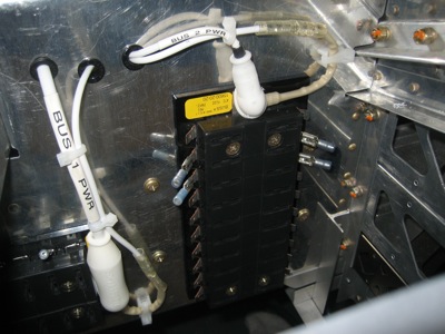
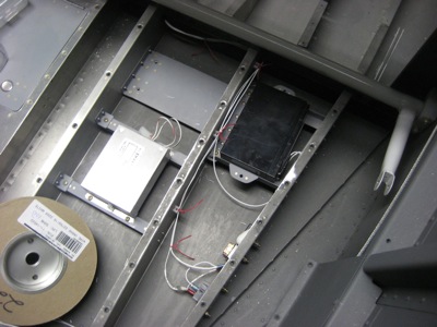
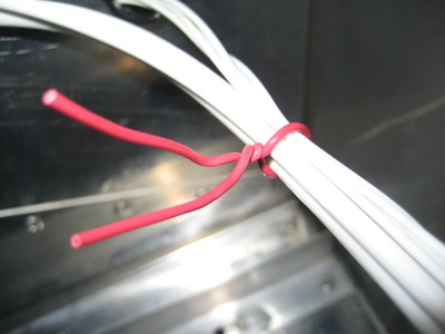
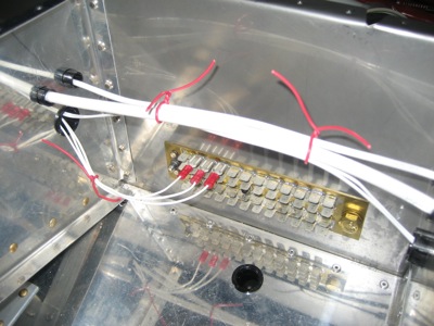
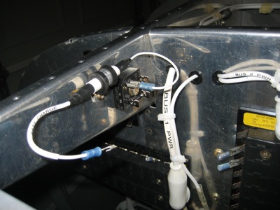
Here's a view from the other side of the subpanel. All the wires are cinched down tight with tie wraps.

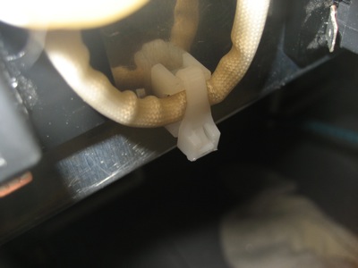
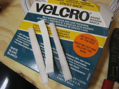
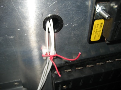
Here's a cool trick… Avery sells these tie wrap bases that have a hole in the middle that's just the right size for an LP4-3 blind rivet. Need to secure a loose wire but don't have anything nearby that you can put a tie wrap around? No problem, just use one of these little guys. I have a feeling I'll be using these by the truckload, all over the airplane.