Archive for the ‘Electrical/Panel’ Category

FWF wiring complete

Sunday, June 21st, 2015

With the firewall-forward wiring finally complete, I spent the better part of a day bundling wires, attaching adel clamps, and replacing all the temporary tie-wraps with the high-temp variety. Now the FWF wiring is all safely secured, and looks pretty good too if I do say so myself. Here's a collection of photos showing the end result. I lost track of the number of adel clamps I installed today and I'm too tired to describe every one!

I also closed out the two firewall passthroughs. The wire bundle is wrapped in multiple layers of firesleeve and clamped solidly, which should keep the flames on the hot side of the firewall in the event of a bad day. I also applied copious lengths of silicone tape to seal the ends and prevent hydrocarbons from soaking into the fibers. Here's the starboard side:

And here's the one on the port side:

I will probably put some kind of sealant on the inboard side of the firewall passthroughs as further proof against fumes and carbon monoxide, but that can be done later.

Being able to check off a major family of firewall-forward tasks is huge! I'm sure I'll get stuck and frustrated again soon enough, but for now it's a great feeling to be able to call the FWF wiring done.

Ground power plug

Sunday, June 21st, 2015

The last remaining wiring task forward of the firewall is some kind of power connection for use on the ground. There are two schools of thought on how this ought to be done – at minimum, a ground power connection should be capable of charging the aircraft battery and perhaps powering the important avionics during maintenance, but some folks also like to be able to jump-start their airplane from a power cart in the event of a dead battery. The problem I found with the latter approach is that the connector required to support starter cranking current is expensive and huge, and there's not a great place to mount it without cutting into important fuselage structure. I also decided that in my electrically-dependent airplane, it wouldn't be wise to get a jump-start and then immediately go flying with a sick battery. So, my ground power circuit will be capable of connecting a battery charger or a small power supply to run the avionics, but to save weight and complexity it won't be able to crank the engine.

For the ground power connection I needed a connector that's lightweight and rugged but still able to handle plenty of current. I selected an Anderson Powerpole connector, which is widely used in the amateur radio field for high-current applications. These connectors are kind of cool, in that multiple poles lock together in with dovetails in a variety of orientations, allowing you to create any kind of custom connector you want. For this application, though, I stuck with the de facto standard arrangement.

Of course, what's a new connector without a new crimper to go with it? I couldn't figure out how to buy just the dies for these connectors, at least not ones that would fit any of my existing crimper frames, so I ended up with a whole new crimper just for a couple connections. Oh well, as a tool junkie I can't complain too loudly.

The ground power connector is secured near the oil dipstick, so that it will be possible to access it through the oil door without removing the cowl. The wiring is 12-gauge, which will be good for up to 15 amps. The black side of the connector finds its way to the main ground block, and the red side connects to the always-hot battery bus through a 15-amp fuse.

Another closeup view… The wiring is tied off and clamped in such a way that nothing can flop around and abrade itself or anything nearby. I left a decent service loop in case I decide I need to relocate the connector later on.

I fabricated a short Powerpole harness for my bench power supply, plus a ten-foot extension cord with Powerpole connectors on both ends. I plugged it all in and verified it works to power up the panel, so that's that. I'm sure this will get a lot of use, both during construction and afterwards.

EGT/CHT wiring

Monday, May 25th, 2015

The last major firewall-forward wiring job is to connect the thermocouples that measure exhaust gas temperature (EGT) and cylinder head temperature (CHT). There's two probes per cylinder, so it ends up being a fair number of wires.

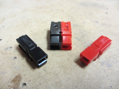
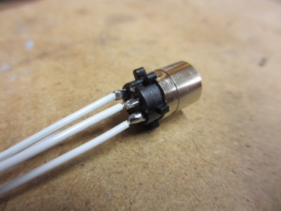
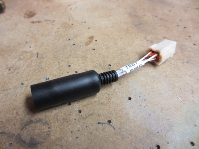
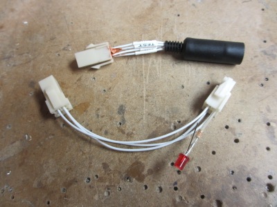
Rather than using the old-style ring terminals to connect the thermocouples, I decided to use these cool little connectors from Omega Engineering. A lot of aircraft manufacturers are switching to this method of connecting thermocouples since they're easy to work with and there aren't any concerns about insulating the connections.

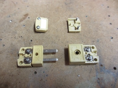
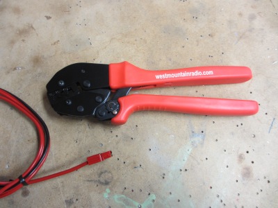
I cut off the ring terminals and installed the connectors on all eight probes. By the way, you have to be careful when wiring Type K thermocouples… the red wire is the negative side!

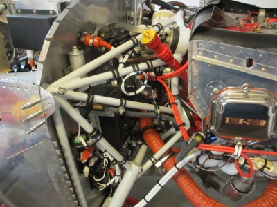
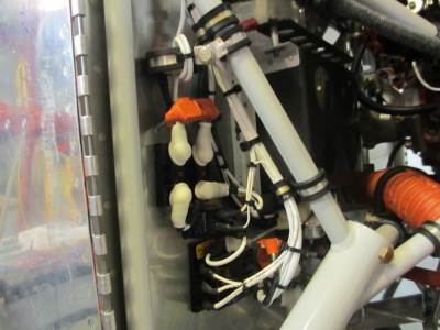
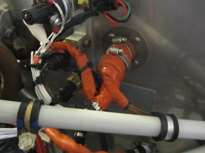
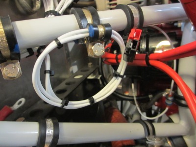
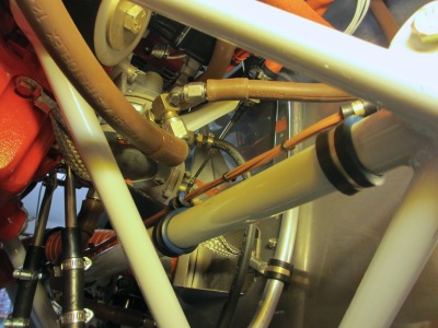
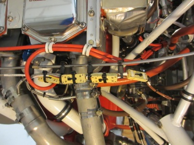
I'll skip over the couple days I spent working out the wiring routes and strain relief arrangements, and just walk you through the final product. Starting on the starboard side of the engine, the thermocouple leads and connectors are all bundled up and secured with high-temp tie wraps:

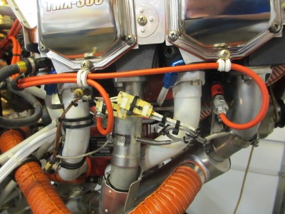
I made a little standoff out of a strip of 4130 steel, painted for corrosion resistance. It ties into the lower valve cover screw on the #3 cylinder and supports an adel clamp that secures the wire bundle. In this photo it's held on by a cleco since I intend to replace it with a high-temp silicone clamp when I get my next parts order in the mail.

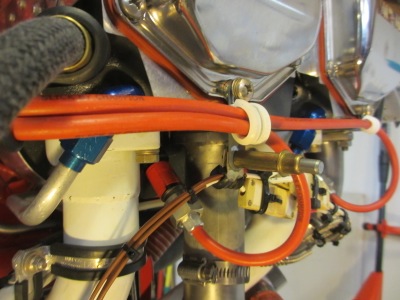
The wire bundle goes down the #3 intake tube, where it's secured by another pair of adel clamps near the bottom:

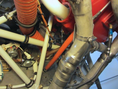
It's sort of hard to see in this photo, which is looking up at the bottom of the right side of the engine, but the bundle of thermocouple wires loops around a diagonal engine mount tube and attaches to the transverse tube with more adel clamps. Although it doesn't look like it in this photo, there is plenty of space between the wires and the diagonal tube.

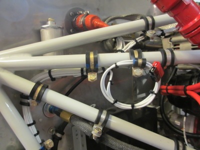
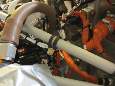
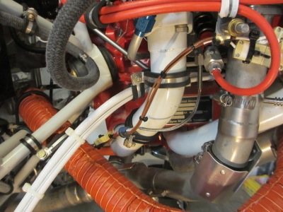
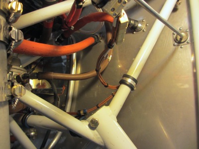
Now we're on the left side of the engine, looking across to the right. The wire bundle crosses the aircraft, following the transverse engine mount tube via three pairs of adel clamps:

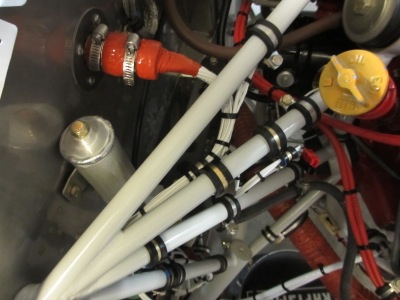
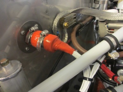
At the port-side landing gear socket, the wires turn the corner and head up one of the engine mount tubes towards the top corner of the firewall. Yet another pair of adel clamps routes them up the tube, and the wires for the #2 and #4 cylinders split off here as well:

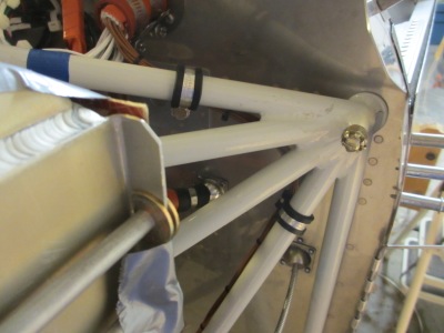
The main wire bundle runs up the back of the tube, where it's attached with… you guessed it, another pair of adel clamps:

At the top of the engine mount, one more pair of adel clamps helps the wire bundle turn the corner, and then it disappears through the port-side firewall penetration:

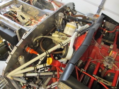
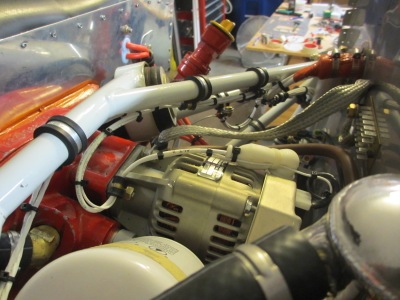
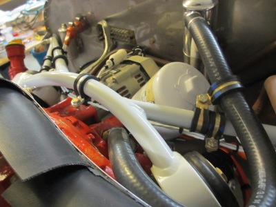
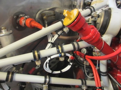
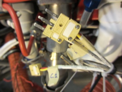
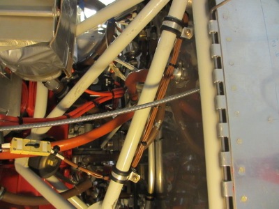
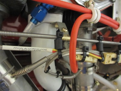
Meanwhile, the wiring on the left side of the engine is more straightforward. The wires and connectors are all bundled together and tied off – you can also see how I ran a tie wrap through the middle hole in each pair of connectors, to help prevent them from pulling apart:

I used the cable for the alternate air door as a convenient way to route the wires on this side of the engine. I cut some 1/2" lengths of rubber fuel hose, and used more high-temp tie wraps to hang the wire bundle from the cable sheath. The result is a neat way of running the wires that looks nice and keeps them away from the ignition leads:

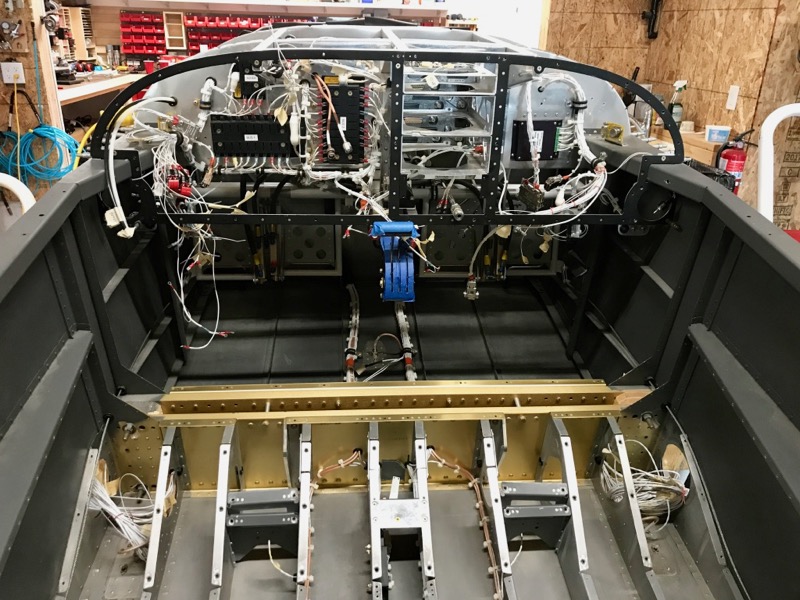
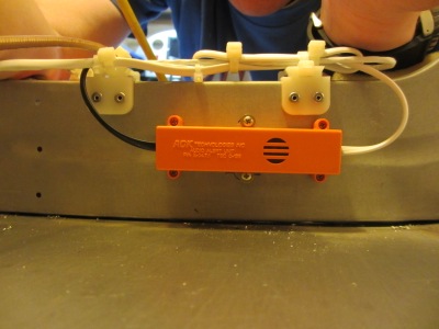
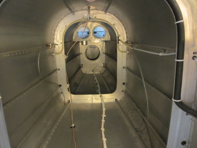
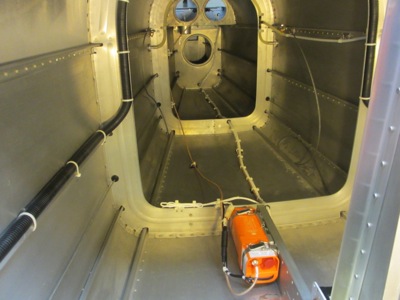
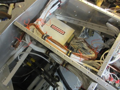
Inside the fuselage, the thermocouple wires are connected and more or less bundled, although at some point in the future I'm going to have to schedule an epic tie-wrapping session for the behind-panel wiring:

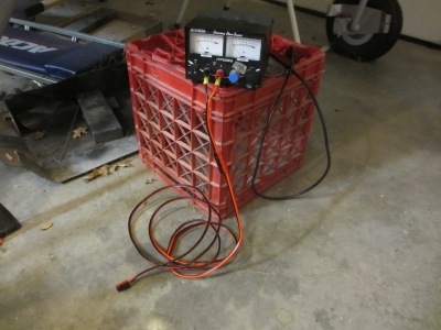
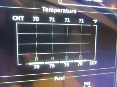
All eight of the probes are reading room temperature, which is a good sign. The fact that the #2 EGT is reading a little higher is just a rounding fluke – the EGT temperatures are rounded to the nearest 5 degrees.

I lost track of the number of adel clamps I installed as part of this little project. It sounds easy now, but each pair of clamps was a mini-nightmare all by itself. These clamps are difficult enough under benign circumstances, but in the FWF area where you can barely get your fingers on them, let alone a wrench, it can seem nearly impossible at times. I hope I don't have to install any more adel clamps for a good long while.

ELT wiring

Sunday, May 3rd, 2015

The ELT uses a fairly rinky-dink DIN connector for its power and GPS position inputs. Rather than trying to solder these tiny pins while standing on my head inside the airplane, I decided to solder them on the bench instead:

Then I fabricated a short DIN-to-Molex adapter. Inside the airplane I used a mating Molex plug with crimp pins.

What this enabled me to do was to also build an in-situ test adapter, complete with diagnostic LED. Then instead of having to leave the wire for the LED in the airplane all the time, I can just plug this little thing into the harness and watch the LED blink when the ELT gets data. Which is what I did – sorry, it didn't photograph well, so I can't show you a picture.

The ELT also comes with a separate little box, containing a buzzer that sounds when the ELT is activated. I suppose that would help the CAP find a crunched airplane in a forest, for example, but I expect its main purpose is to alert bystanders to an accidental ELT deployment after a hard landing or whatnot. I mounted the audio box on the aft side of the F-707 bulkhead:

The audio box uses its own battery, an unusual 3V lithium number. I'll need to crawl back there and replace it in 2024:

I secured all the wires that go to the ELT, and there are actually quite a few. I used plastic tie wrap anchors to route the wires to and from the audio box, whose mounting screws are visible here on the forward side of the bulkhead:

I fabbed a length of RG400 coax for the ELT antenna, and used more plastic anchors to secure it loosely to the bulkheads and floor.

Everything is shipshape in ELT land now, I believe. Per the manufacturer's guidance, the antenna cable does not penetrate any bulkheads or aircraft structure, and is only loosely restrained elsewhere, so it can still move around and hopefully won't get cut during a… shall we say, "a deceleration that rearranges the configuration of the airframe".

Transponder antenna cable

Sunday, May 3rd, 2015

One last job to finish up the transponder installation – crimping the BNC connector and securing the short run of coax that goes from the transponder to the antenna. Done and done: