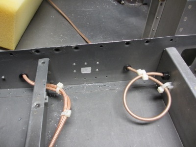
One last job to finish up the transponder installation – crimping the BNC connector and securing the short run of coax that goes from the transponder to the antenna. Done and done:
![]()
One last job to finish up the transponder installation – crimping the BNC connector and securing the short run of coax that goes from the transponder to the antenna. Done and done:
![]()
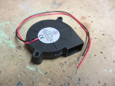
One of the unfortunate side effects of mounting the transponder underneath the baggage floor, as I did, is that the hot transponder is trapped inside a box with no air movement. The transponder puts out 250 watts, and I didn't want it cooking itself under there, so I engineered a little cooling fan setup to help keep its temperature under control. I started with a cheap 12V squirrel cage blower meant for desktop computers:
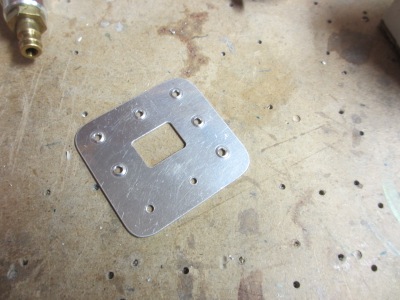
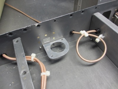
I made this little mounting bracket out of scrap aluminum. The big hole in the center is sized to fit the opening in the bottom of the fan.
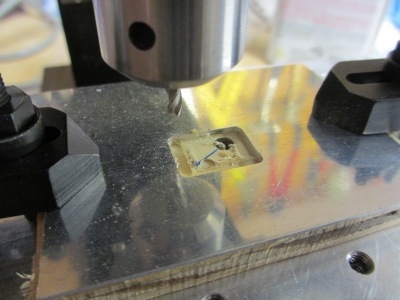
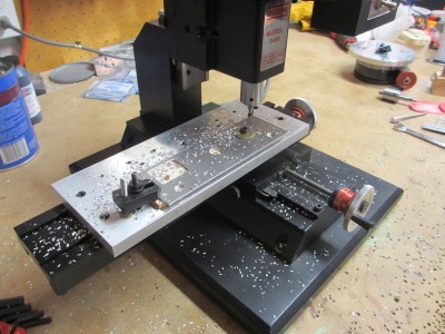
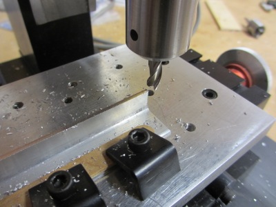
The cooling fan will exhaust through a hole in the F-706 baggage bulkhead, which means I need a doubler plate for the hole. Since the fan has a rectangular outlet, I used the mill to cut a matching hole in a piece of 0.050" scrap:
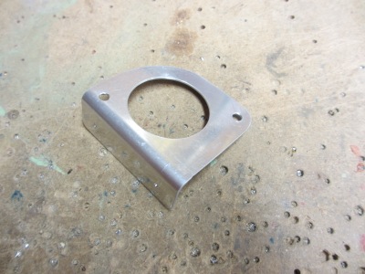
Here's the finished doubler – nice round corners on that hole, thanks to the milling machine. I love the milling machine, even though I'm a complete novice at using it.
Inside the airplane, I used a unibit and files to make a matching square hole in the bulkhead, below the level of the floor. The hole isn't nearly as pretty as the machined one in the doubler plate (nor is it as weirdly trapezoidal as it appears in this photo!) but it will serve its purpose. I did make sure not to leave any square corners, lest they provide a place for cracks to develop.
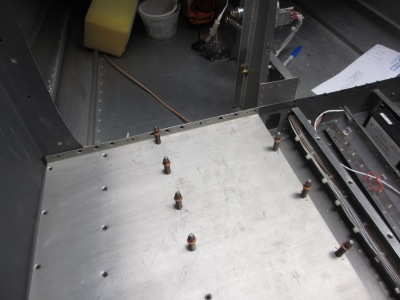
Riveted the doubler plate and fan bracket in place, using a combination of solid and pulled rivets:
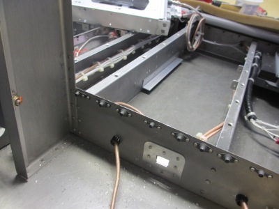
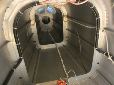
Here's a shot looking forward from inside the tailcone, so you can see the doubler on the aft side of the bulkhead. For reference, the hole dimensions are approximately 1/2" by 11/16", so not all that big – about the same size as the hole for a wiring grommet.
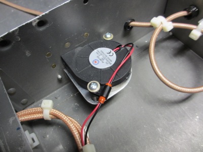
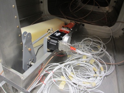
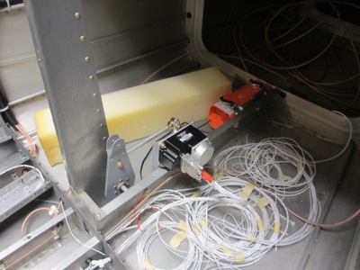
Here's the fan installed on its bracket – warm air comes up through the hole in the bottom of the bracket and exhausts through the bulkhead into the tailcone. I think the tailcone should be a low-pressure area in flight, which should also help move air towards the tail.
Testing to see if it all works – you can't see it in this photo, but the fan is whirring away and blowing air through the bulkhead.
![]()
Everything all cleaned up and reinstalled:
![]()
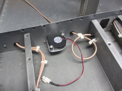
Here's a close-up of the fan, showing how I used a tiny plastic clamp to secure the wires from flopping around:
The fan blows lots of air when hanging in free space, but just for a test I temporarily installed the starboard baggage floor and ran the fan with the floor in place. I was pleased to see that the fan didn't seem bothered by this at all – the pitch didn't change and it still moves plenty of air with the floor installed. I was worried that I'd also have to engineer a cooling air inlet to provide enough input air for the fan to work with, but I guess enough air gets into the transponder compartment through gaps in the corners of ribs and so forth.
To run the fan, I used the switched power output pin on the transponder, which is normally used to power a blind-mount altitude encoder. Since I don't have one of these, I can use that pin for my cooling fan. I measured the fan's current draw at about one-sixth of the maximum current capability of the switched power output pin, so no problems there. The nice thing is that the fan will turn anytime the transponder is on, and I don't have to fish another set of wires through the whole airplane to run it.
No two ways about it, it's time to finish running the wires to the back of the airplane. I've been putting off this job forever, because it's not at all pleasant for me to be stuck heads-down inside a tapering metal tube made of delicate aluminum, trying not to crush the bulkhead flanges with my knees, while groping for dropped tools and burning my face on the shop light. In case you were wondering, that's a pretty apt description of what it's like to work inside the tailcone.
Anyway, I got all the various wires that have to exit the aft end of the airplane bundled neatly and run all the way to the back. Sorry, I didn't take any photos of the process (see previous paragraph).
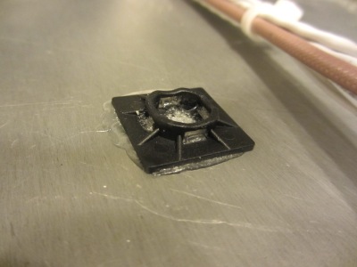
Between the bulkheads, the wire bundle is secured to the bottom skin with tie wraps and these self-adhesive plastic anchors, from which I removed the self-adhesive stuff and attached with E6000 glue:
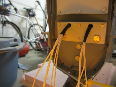
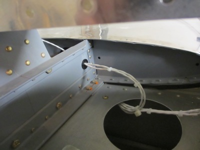
Back at the tail, I had already drilled to holes for passing the wiring through the aft bulkhead and vertical stabilizer spar ages ago. I'm not wild about this method for getting the wires through this area, but with the tailwheel mount being in the way there aren't too many other options.

On the outside, the wires can pass through the holes but there isn't room to use a proper grommet, so I used a couple layers of shrink tubing over the wires to prevent them from chafing on the holes.
For further wiring protection, I squirted RTV into the holes:
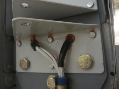
I merged the two wire strands back into a single bundle, and secured them with an adel clamp and a convenient bolt. That ought to keep the wire bundle from getting entangled with the rudder.
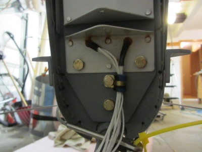
In the above photo you can see that there's a pair of small areas outboard of the vertical stabilizer spar in the lower corners. I might have been able to insert a grommet for a wiring bundle through this area, if I'd thought to do it before installing the tailwheel weldment. Yet another thing I'll do better on the next airplane project.
Some of the wires need to go upwards to the elevator and magnetometer, so they branch off and run up the side of the F-710 bulkhead and through a lightening hole in the aft deck. An adel clamp (invisible in this photo except for its mounting screw) keeps it in place.
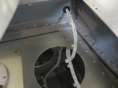
Another view of the same area. The unused hole for the manual elevator trim cable makes a convenient place to put a grommet to pass the elevator trim wires through.
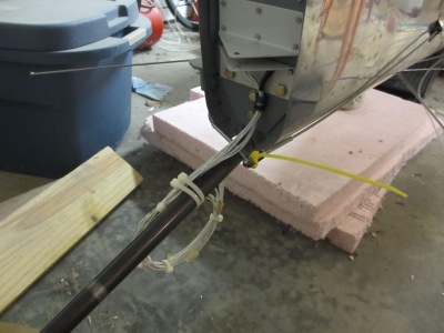
For now I've tied off the wires where they exit the fuselage, so they don't get tangled up with any of the other stuff piled up in my crowded garage:
I couldn't mention it at the time, but the reason I moved my transponder was to make room for a GMC 305 autopilot controller. It's an optional add-on, but I really like how it streamlines the whole operation of the autopilot and flight director, so I wanted to find a way to fit one into my radio stack. The transponder had to go in order to make room for it, but I think it was a fair trade. I already ran the wires to connect it, I just didn't take photos.
The GMC 305 is slightly taller than the GTX 330 transponder it's replacing, so I had to remove the lower filler plate from the bottom of the radio stack and shave off about 0.050" with the milling machine.
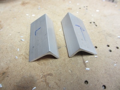
While I had the mill out, I made some 1/2" x 3/4" angle out of scrap material. Having a milling machine sure is handy.
These little angles will become the mounting brackets that will attach the GMC to the radio stack:
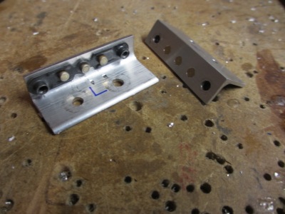
After a lot of fiddling I got all the various mounting holes drilled. There's not technically enough room to fit both nutplates, but the spacing between them is coincidentally perfect to allow two nutplates to share one rivet. That was kind of a lucky break.
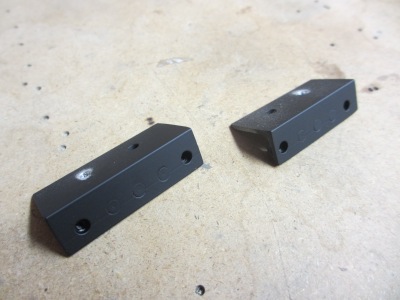
I painted them black since the edges will be somewhat visible from the cockpit:
The brackets are attached to the radio stack mounting rails with #6 screws:
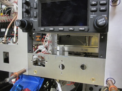
And here's the GMC 305 installed. I don't currently have the proper black cap screws that this would normally use, so I just grabbed some shiny screws from the bin for test fitting purposes.
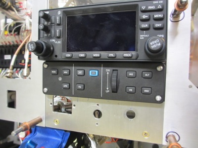
You can see above that there's just barely room for the rudder trim and flap switches now. My panel sure is full of stuff.
I sold my Trutrak autopilot system and changed over to the Garmin G3X autopilot instead. Fortunately the GSA 28 servos fit into the same bolt holes as the old servos, so installing the new pitch servo was straightforward. And it's a bit lighter too.
The electrical connections were surprisingly not that hard to retrofit either. Of course the wiring is very different between the two systems, but the servos use a similar number of wires, so I was able to repurpose existing wiring for new tasks. The old stepper motor drive and torque sense wires became CAN and RS-232 lines – luckily I had the foresight to use shielded wire. The only new wire I had to run was a single conductor for the autopilot disconnect line; in the old system the red button was connected to the control head in the panel, whereas in the new system it connects to both the servos. The power and ground wires stayed the same.
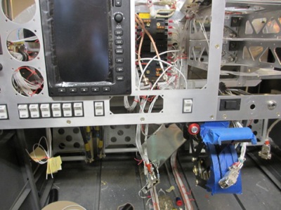
I'll have to come up with something to do with this oddly-shaped hole in the panel, which used to be occupied by the Trutrak autopilot control head. I'll figure it out.
I haven't installed the new roll servo yet, since I need to redo some wing wiring, but the wiring that goes out through the side of the fuselage is now all prepared for the Garmin autopilot.