Archive for the ‘Flaps’ Category

Flap positioning system

Wednesday, May 3rd, 2006

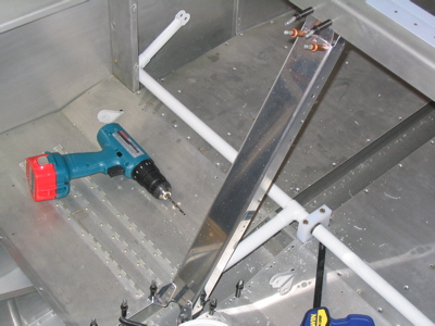
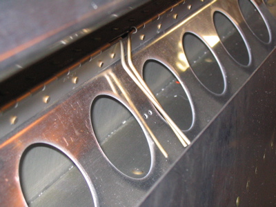
Tonight I installed the parts for the flap positioning system. This is an optional cockpit convenience item, and is not absolutely necessary for flight – however, I really wished I had one when I had the last RV, so into this airplane one will go.

The normal flap system involves a toggle switch that you press and hold to move the flaps up and down; you keep holding the switch until the flaps get to where you want them to be. This is the same arrangement as early Cessna 150's and my old Grumman, among others.

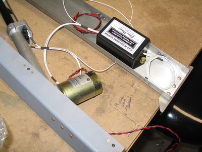
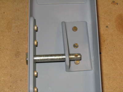
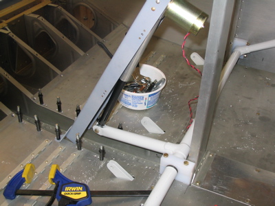
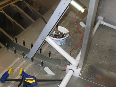
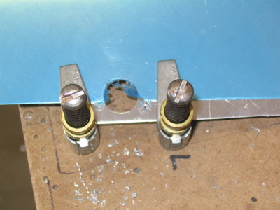
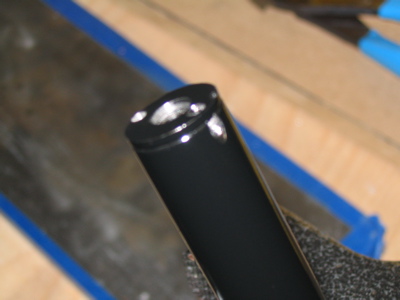
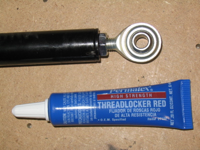
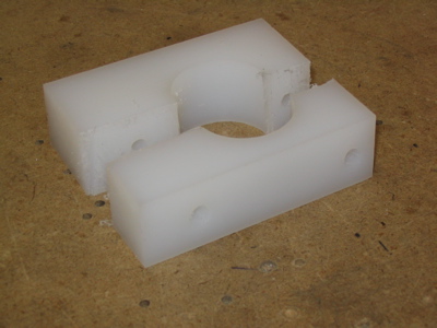
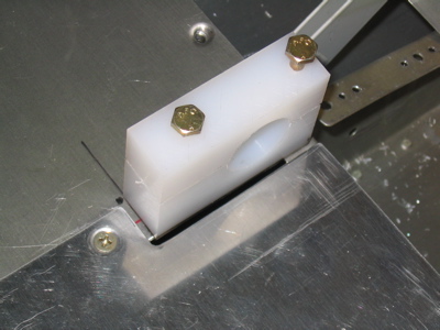
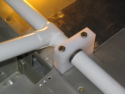
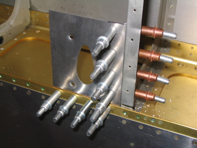
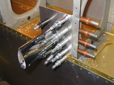
Instead of that setup, my airplane will have this sensor thingy attached to the flap motor – a very clever and simple arrangement involving a machined rod sliding between two microswitches – and a control box mounted nearby. Bumping the flap switch briefly down will automatically lower the flaps one notch each time, and flipping the switch to the up position will run them all the way up. Very cool.

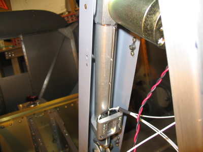
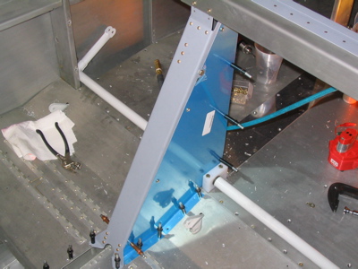
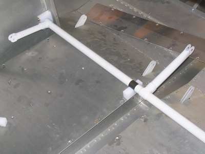
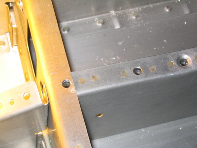
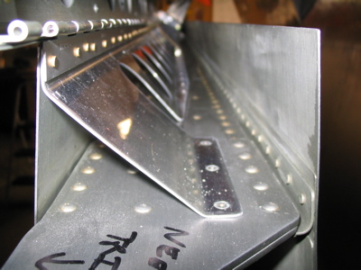
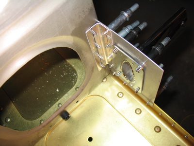
I mounted the control box to the inside of the seat back brace with screws and nuts. It's kind of a pain the way the flap motor and control box are permanently wired together – it certainly makes handling these parts problematic. I'll probably cut the wire bundle and splice in a connector so the flap motor can more easily be removed for maintenance.

Flap actuator

Sunday, April 23rd, 2006

Here's a collection of pieces that had to be fabricated for the flap motor mount:

The flap channel gets fitted thusly. The plans call for the joint plate at the top to be bent to an angle of 151.8°. Yeah, whatever – we're not building the space shuttle here. I just adjusted the bend angle until everything fit and drilled it in place.

Here's a shot of the rear side of the flap channel, where the motor pivot bolt goes through. The angle bracket is a little crooked, but that's how the motor geometry worked out. I've seen this on other builders' sites so I don't think it's a problem.

The motor can run the flaps through the entire range of motion without binding or rubbing anywhere. This is up:

This is down:

I got the side panels mostly fitted before calling it a day. With everything in place the flap motor has a little house to live in. I still need to deburr the side panels.

On the left side, you have to notch the side panel to clear the pivot bolt head. I clamped a piece of scrap aluminum to the edge of the cover and used a unibit, which worked well.

Flap actuator safety hole

Wednesday, April 19th, 2006

The only thing I got done tonight was drilling this little hole at an angle through the end of the flap actuator. In the photo, you can also see the first hole I tried to drill. The bit broke off in the hole and I had no way to get it out, so I had to start another hole. The end of the actuator was also kind of scraped up after all this, so I sprayed some more black enamel on it.

The idea is that you put safety wire through here and it prevents the jam nut from backing out as the flaps go up and down. I'm dubious that this will work very well, so I used permanent threadlocker on the rod end bearing and jam nut when I threaded them into the actuator.

Installed flap torque tube

Sunday, April 16th, 2006

This afternoon's mission: install the flap torque tube. The clevis ends of the weldment got drilled and reamed up to 1/4" for the bolts, and then I drilled and split the center bearing block. My block as supplied was about 1/2" longer than the plans call for, which made where to locate the aft bolt hole a head-scratcher. I decided to put it in the same place it would be if the block was the size called out in the plans, instead of putting it 1/4" from the edge. This turned out to be a good idea (see below).

The weldment is inserted into the end bearing blocks, and the whole mess is put in the baggage bay. It's a tight squeeze but it can be wiggled into place. The center bearing block goes over the left-center subfloor rib. I've heard that some people have trouble with the non-powder-coated part of the weldment ending up in the wrong place, but you can see that mine lined up okay.

After making sure the center bearing block is centered over the rib, I drilled down through the block into the floor and rib, then removed the whole mess and put in nutplates to capture the bolts. Good thing I decided to move the aft hole away from the edge of the block, or the #10 hole would have been uncomfortably close to one of the #8 nutplates that holds the tunnel cover to the ribs.

I notched the tunnel cover so it can be removed without unbolting the flap bearing block. The left side baggage floor is captured by the flap block, so it will be a little harder to remove easily. That means I'll put the strobe power supplies under the right-side baggage floor, which I was planning on doing anyway for lateral balance purposes.

The whole collection of parts is now bolted in place yet again, although it will certainly be removed and replaced several times later on.

So, the flap torque tube is fitted and installed. Next up is the motor and its housing, probably not until next weekend when I have some time to work.

Attached flap hinges / Started pitot

Thursday, December 29th, 2005

I got up this morning and primed the flap braces (only on the side that won't eventually be painted) and then riveted the flap hinges to the wing bottom skin and the flap braces. Notice how the temporary rivet holes are now filled with small-head rivets that have their flush surfaces facing out. Also visible here is the section where I removed three hinge eyes to allow insertion of the flap hinge pins, per the plans.

Here's the backside of the same area. During final assembly I'll capture the bent ends of the hinge pins with some safety wire through the little holes I put in the flap brace.

The flap brace itself is riveted to the rear spar with monel rivets along the entire length, with the exception of the three inboard-most rivets – those are Cherry flush structural blind rivets. Big, solid-looking suckers. Cool.

Here's the finished product. The alignment is correct and the motion of the flaps is smooth throughout the entire range of motion. The outermost foot or so of the hinge isn't riveted yet, since the outboard bottom skin doesn't get riveted on until everything inside the wing is finished.

Once I got the flaps on for good, I started messing around with the pitot tube. I'm planning to mount it just outboard of the rib bay where the aileron bellcrank lives. The Gretz bracket is match-drilled to the spar flange, and a piece of angle stock I cut ties it to the rib. Here's some random photos of the setup so far:

I'm not totally happy with the way the backing plate is a little bit recessed from where the skin will be. I'll probably have to make a shim from 0.020" Alclad or thereabouts.