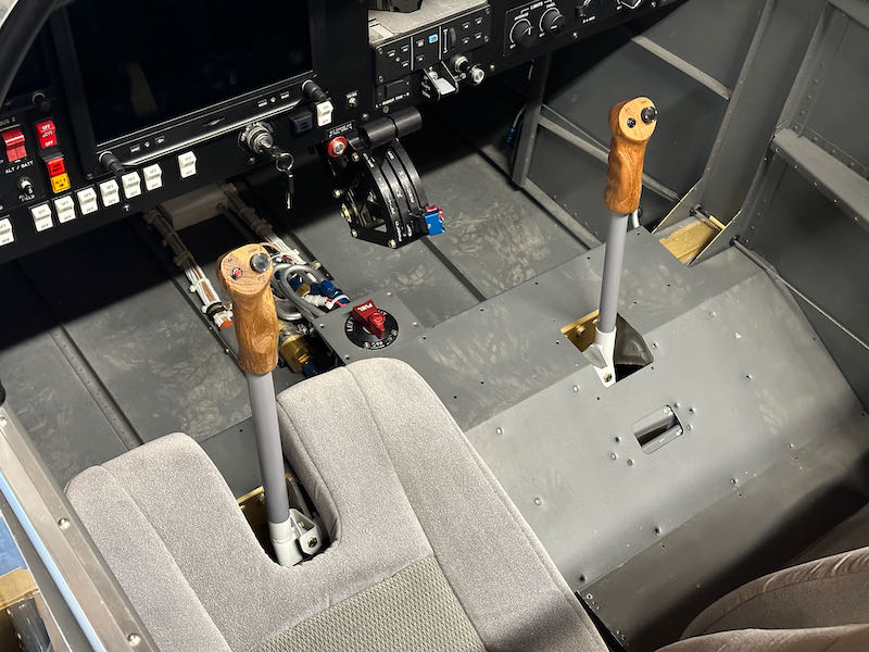
Interior fitting

July 20th, 2023

I got the Classic Aero interior panels out of storage so I could finish fitting them to the fuselage. Even just sitting loosely in place, they look pretty good:
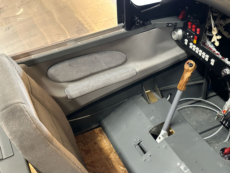
I don't love this gap at the top of the center section, but I don't currently have any good ideas for how to address it. I just minimized the gaps as best I could, then drilled and installed the nutplates that hold the forward end of each interior panel to the F-902 bulkheads:
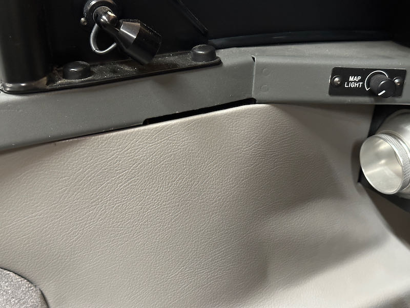
I installed nutplates in the F-705D channels to secure the aft bottom corners of the interior panels. This also involved changing the upper screw and nutplate holding each F-749 flap cover to a flush fastener to fit underneath:
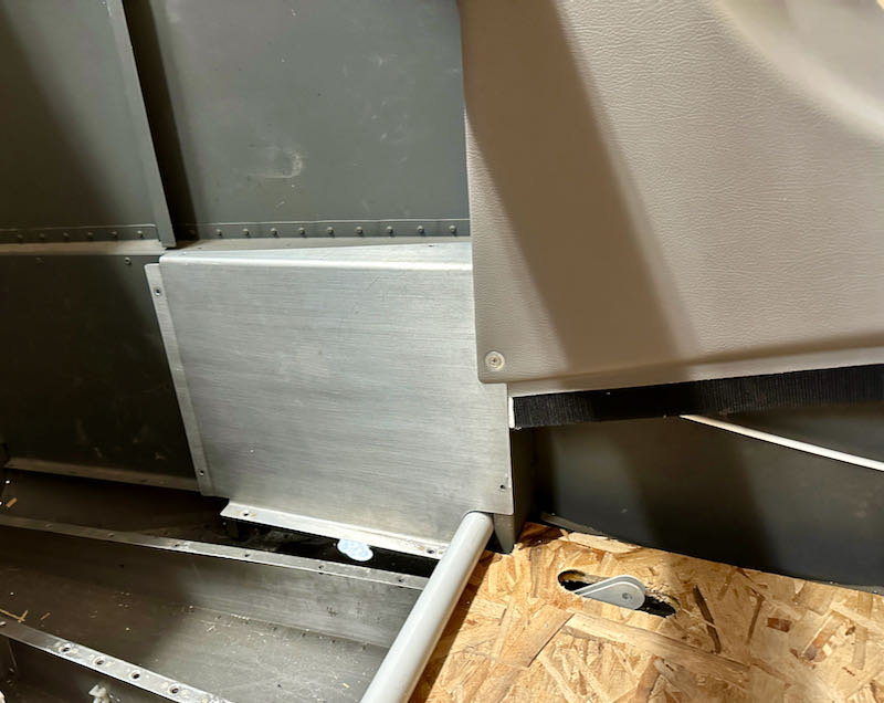
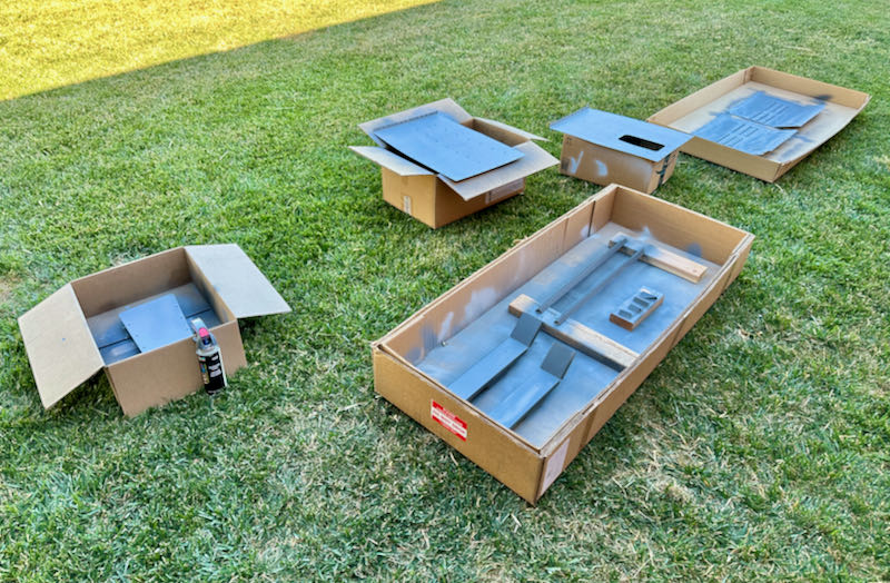
I picked up some more Rustoleum textured paint and sprayed a bunch of interior pieces:
Long ago I fabricated some improved stiffener angle pieces to reinforce the armrests, a known weak spot in the design of the interior of these airplanes. Somehow I forgot to document this, but here's everything painted and riveted together. There's a piece of 0.062" angle tucked under the armrest flange, which attaches to the center section and F-705 bulkhead with a pair of little brackets. You still wouldn't want to jump up and down on them, but the armrests are now much stronger than stock. Naturally I also riveted the F-704K center section cap strips at the same time:
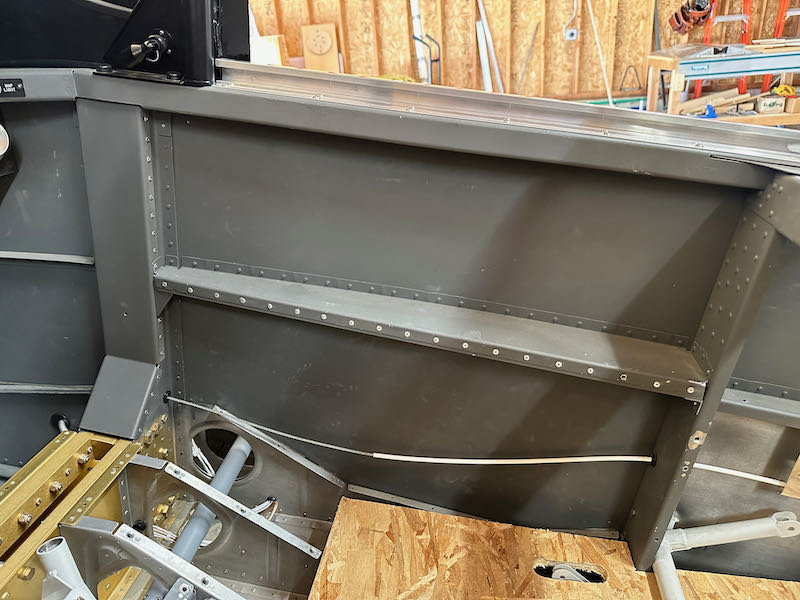
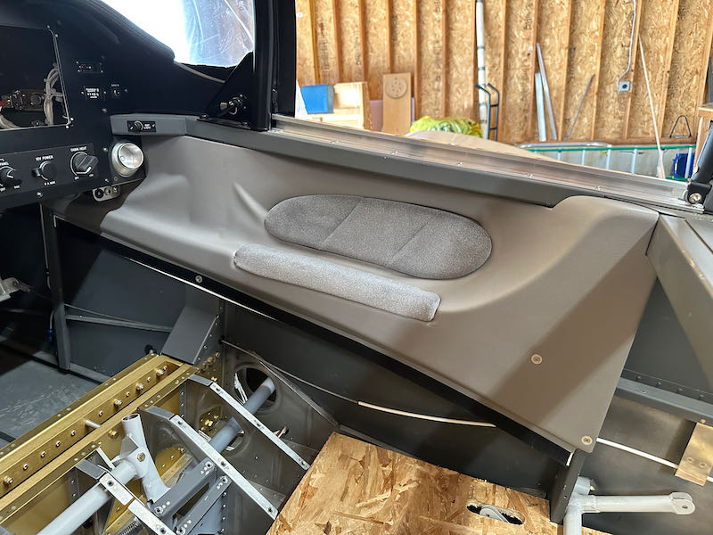
It's hard to see in the above photo, but there is a nutplate in the F-704K and another one near the aft end of the armrest. Into these I drilled screw holes for two more screws, one into F-704K in an area that will be hidden by the lower side panel, and one into the armrest that will be hidden by the seats when they are installed. Of course, getting these located correctly took some advance planning. With four screws installed, the upper interior panels are pretty secure:
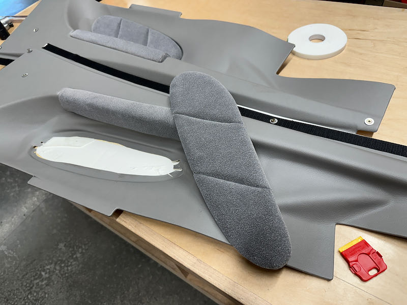
I've had these interior parts so long that the faux-leather material has started to separate from the plastic panels, and the foam tape attaching the elbow pads has more or less given up the ghost. I'll have to do something about all this eventually, but for now it's good enough just to have the fasteners that hold the panels finalized:
Rudder cable guards

July 3rd, 2023

As seen previously, the rudder cable runs directly above the flap weldment and pushrods. The plans call for the flap pushrod bolts to be inserted from the outboard side facing inward, putting the bolt head between the weldment and skin. Apparently this is to reduce the chances of having the rudder cables get hung up on the flap mechanism. This is a fine idea, but it's also annoying and impractical as it requires the entire flap weldment to be removed in order to remove or reinstall these bolts. Here I have the bolts temporarily installed facing the opposite direction, which is much easier:

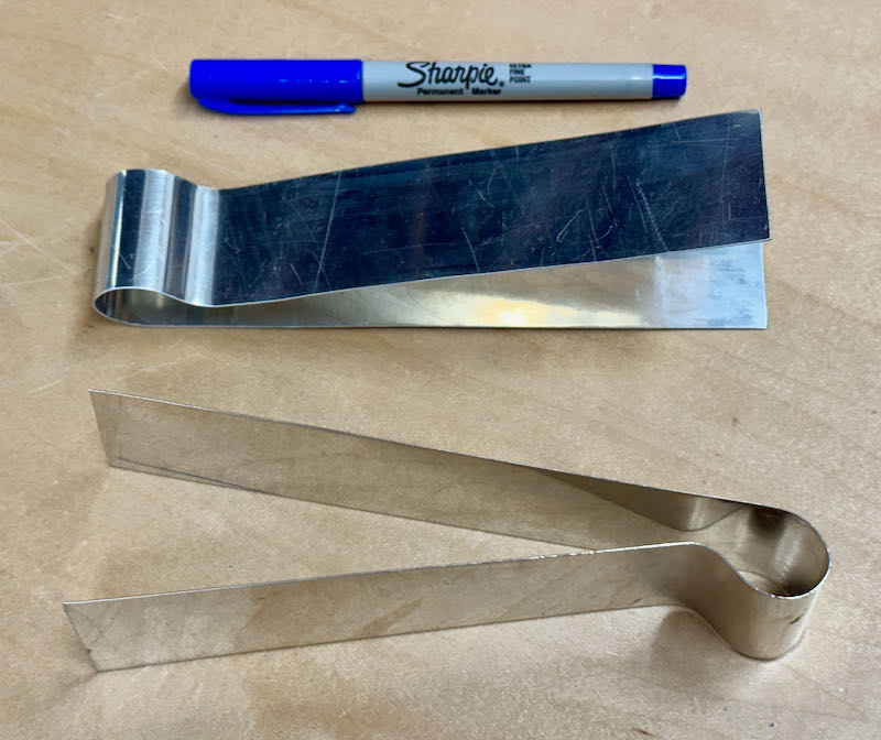
Rather than accepting this state of affairs, I decided to solve the root problem more definitively by making a pair of rudder cable guards out of 0.020" scrap:

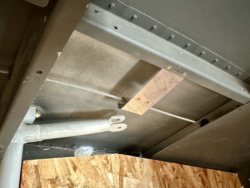
The cable guards are riveted to the inside of the flanges of the F-722 horizontal ribs, and will prevent the rudder cables from ever getting tangled with any part of the flap mechanism. They will eventually be hidden behind the F-749 baggage side covers:

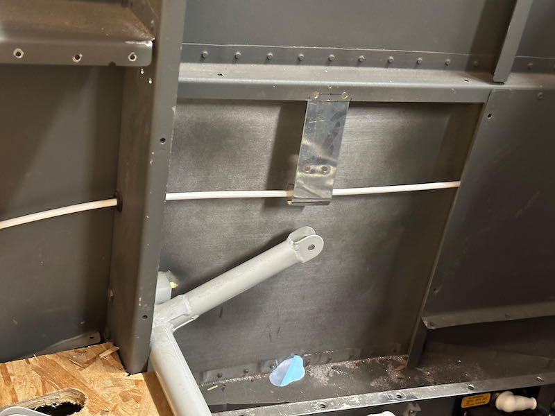
Under normal circumstances the rudder cables are in tension, and will pass through the cable guards without touching. However, when the airplane is parked, it's possible for the cables to sag a bit. Just for a little bit of extra protection, I added some plastic cable covers from the local boat supply store. Now even if the rudder moves in the wind, the cables won't rub directly on aluminum:

Just one of a million little projects that have to get finished, before the Project can get Finished…

Flap pushrods

June 25th, 2023

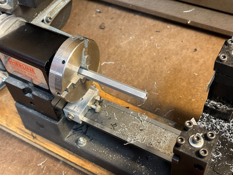
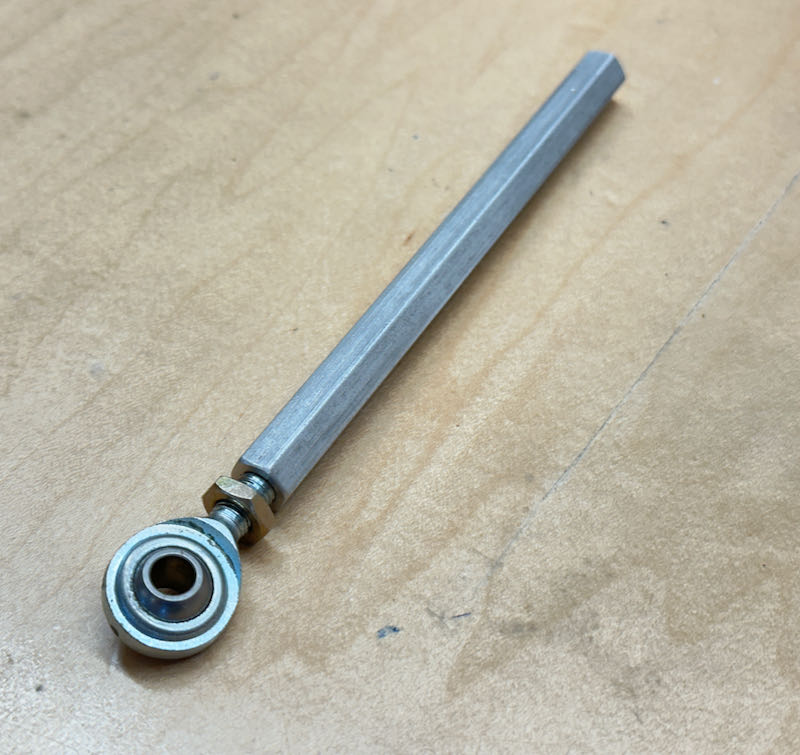
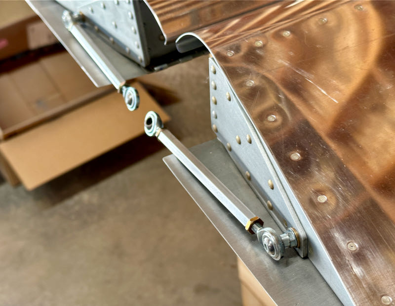
After trimming the flaps to fit nicely to the fuselage, the next step is to finish the mechanism that operates them. The RV-7 plans have you make a pair of pushrods by tapping the ends of some fairly skinny aluminum tubing, but I decided to follow in the footsteps of others and use the beefier hex stock normally used by the RV-9. Since the RV-7 uses shorter pushrods, the easiest way to do this was to simply buy the RV-9 parts and cut them to the correct length:

Real machinists are cringing at the unsupported length in the above photo, but since I didn't have a good way to support these pieces while facing the ends, I just took light cuts and worked carefully. Here's a finished pushrod with one rod end bearing installed:

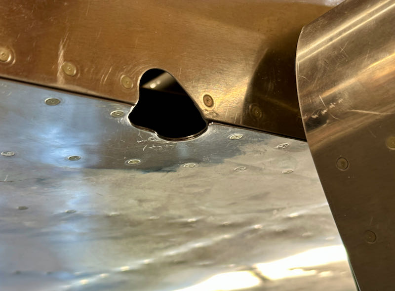
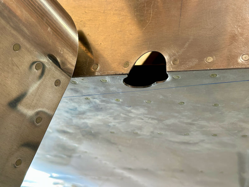
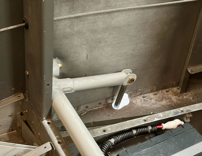
The most challenging portion of this part of the project was cutting the holes that allow the flap pushrods to pass through the fuselage bottom and sides without binding. I'm told that these are prepunched on the RV-14, which must be nice, since they have to be a strange 3D shape that can only be determined iteratively. I didn't take any pictures of the process, but there was a lot of tedious test-fitting, marking, and grinding until I achieved a satisfactory result:

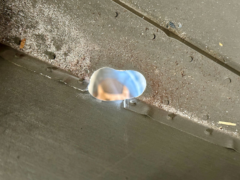
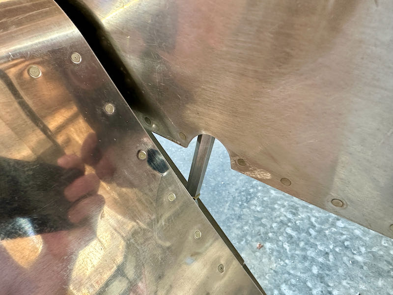
Here's a view of the same hole from the inside looking down. I still need to clean up the mess of aluminum dust and sanding-wheel particles from inside the fuselage:

I must have installed and removed this pushrod a hundred times before I got the shape of the hole right. Here you can see that there is adequate clearance all around when the flaps are in the full-down position:

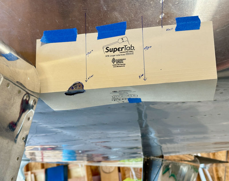
Finishing the first first hole took me an entire day and then some. Instead of starting from scratch on the second hole, I used a piece of manila folder to make a rough template that would give me a head start:

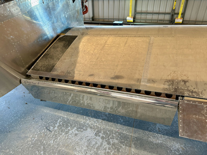
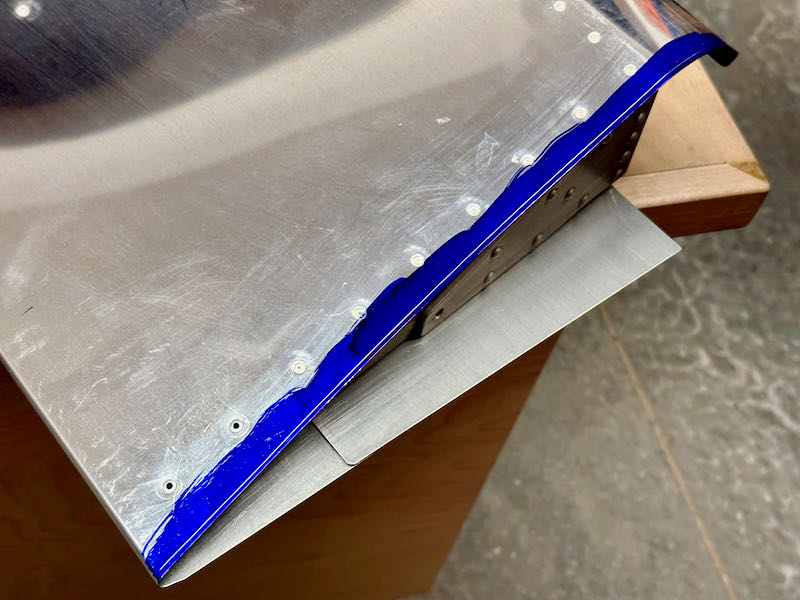
Here's the second hole, which only took me a half-day to finish. The blue line indicates where the flap bottom skin ends, showing that the hole will be completely hidden when the flaps are up:

I have to say, this whole pushrod-hole situation seems like a real afterthought to the design, and the way they have you grind your way through the corner of fuselage is pretty barbaric. And I'm not just saying that because I slipped with the sanding drum and scuffed up the fuselage skin:

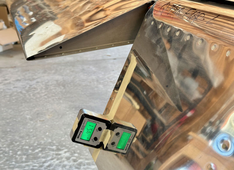
The plans list the flap travel limit as "40-45 degrees maximum", which is less than precise, but I don't think there is actually much adjustment possible with this mechanism – you just have to take what you get. In my case I am right at 45 degrees at full-down, which is acceptable. I haven't hooked up the flap positioning system yet, so this may be reduced slightly in the future.

I don't want to install the flap mechanism permanently quite yet, and I don't want to damage the flaps while crawling in and out of the fuselage carrying tools, so I removed them from the wings and set them aside for now. While I have improved access to the lower rod end bearings, I removed and reinstalled them with lock washers and blue Loctite in accordance with the plans:

Still some work to be done before the flap system is truly finished, but it was neat to be able to hook up a battery and watch the flaps go up and down.

Flap fitting

June 2nd, 2023

I got the flaps down from the attic and installed them on the wings to see how they fit:

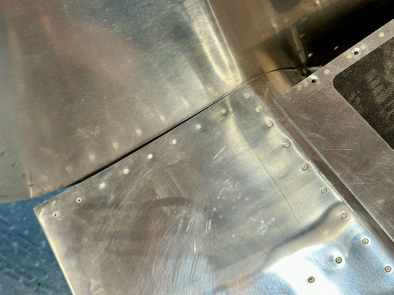
As expected, the inboard ends needed a little work to properly fit the fuselage. The flap skin was rubbing on the fuselage in places, and the gap was generally unsightly. The plans don't specify how much clearance you need here, but I've seen numbers anywhere from 1/16" to 1/8" mentioned. I decided to split the difference and shoot for a nice consistent 3/32" gap.

Instead of using a sharpie, I painted each flap skin with marking fluid and then scribed a line along the fuselage side with a 3/16" brad-point wood drill bit. Result, a perfect 3/32" line. (click for the big version to see it)

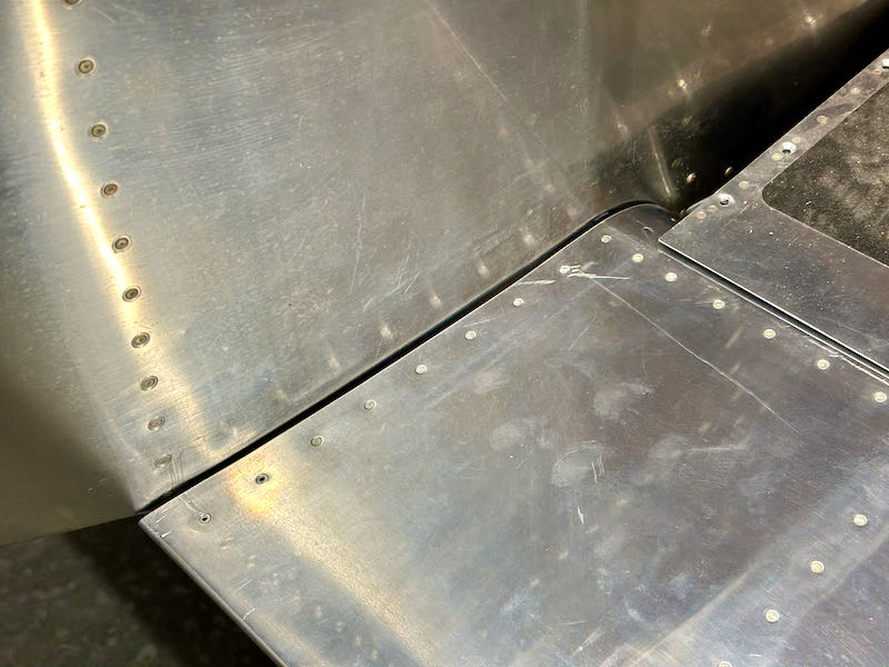
From there it was a simple matter of cutting and filing up to the line. After a couple iterations I was able to achieve a nice even gap that looks pretty good:

Stick grips & wiring

May 27th, 2023

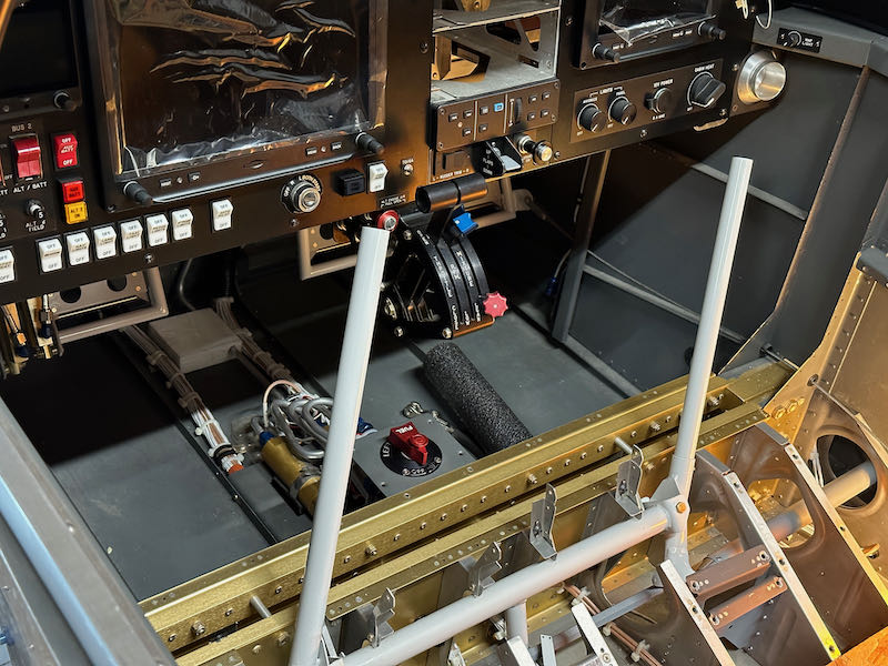
When we last saw the cockpit flight controls, I had the control stick geometry worked out but didn't have the stick grips installed yet:

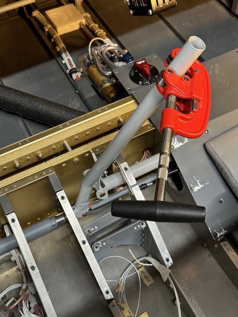
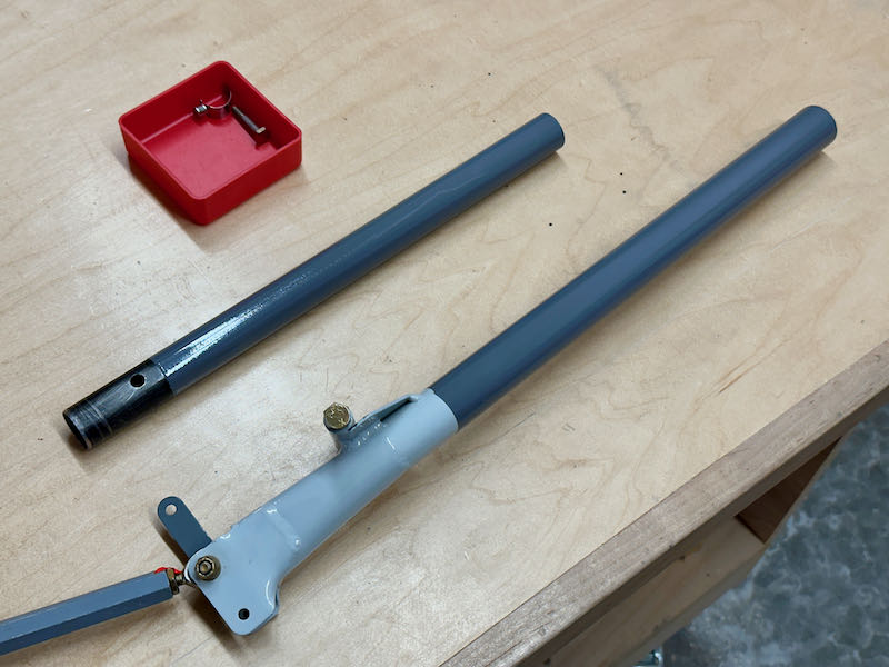
The stick grips add some length, so the tubes have to be shortened to result in control sticks that are the correct length. I did this iteratively, to sneak up on the correct dimensions without making the sticks shorter than they need to be:

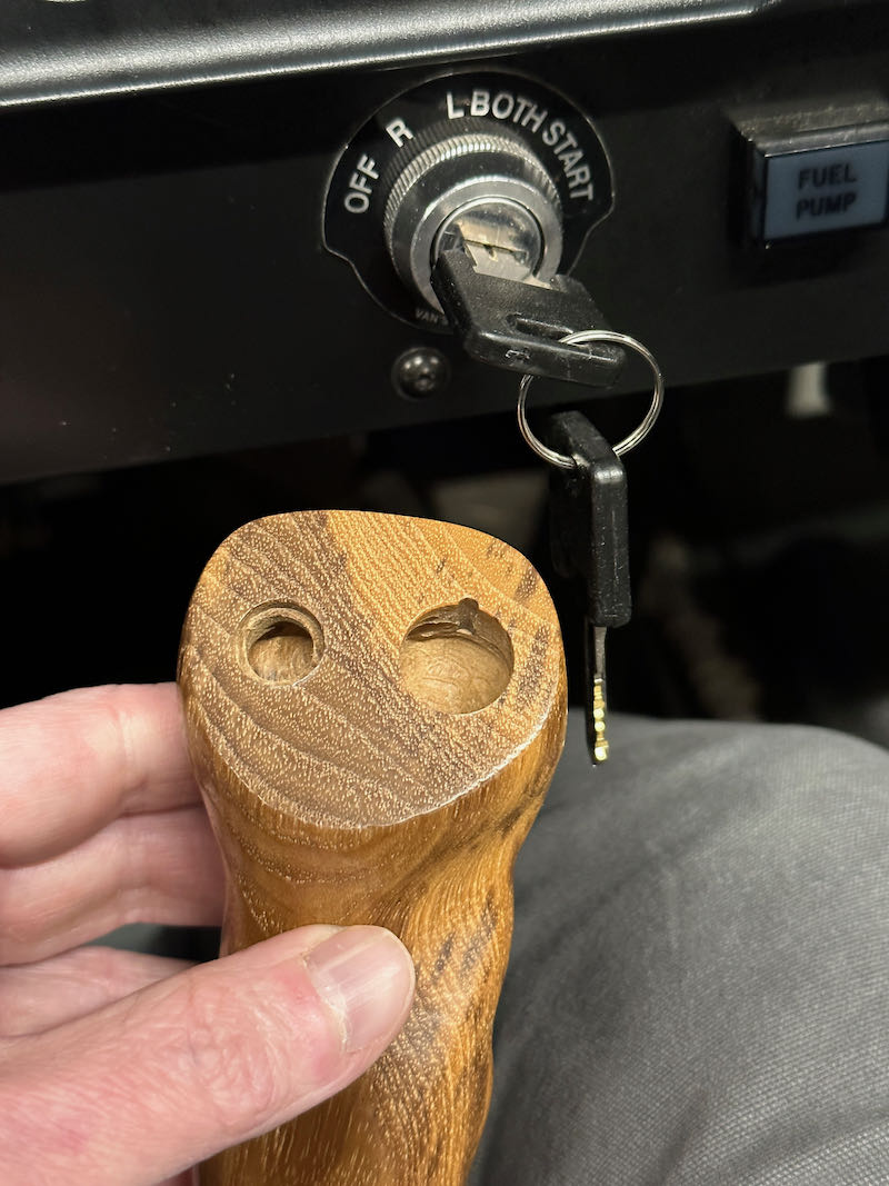
Frustratingly, with the sticks trimmed properly, the pilot stick grip hits the start key when moved to nearly full forward-right deflection. This was an unwelcome surprise:

This type of interference can't be allowed to exist, but I didn't want to shorten the sticks even further and affect the flight characteristics of the aircraft, so I was presented with a dilemma. Ironically, the part of the stick grip that contacts the key is the forward protrusion that used to house the start button – which is no longer required now that I've moved the starter control to the panel.

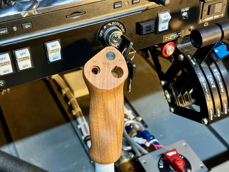
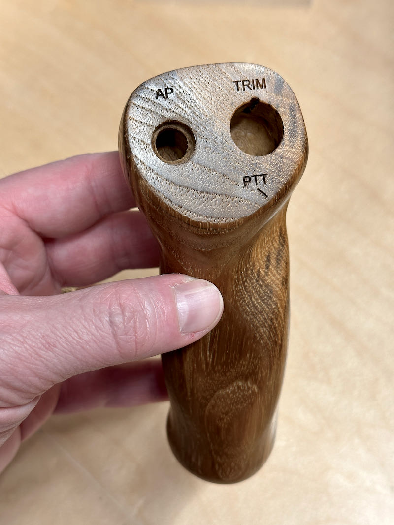
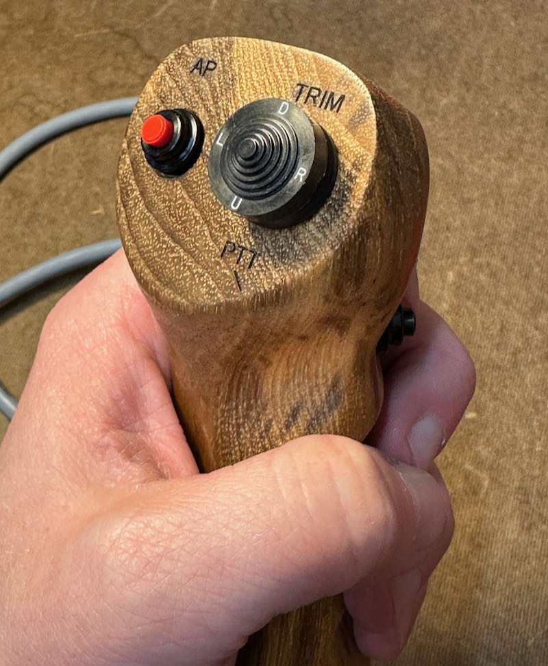
So, I figured the only workable solution was to have a new grip made. After a few emails with the manufacturer and the expenditure of a modest sum, I had a brand-new wood grip in hand. This one has the same functions as the old one, minus the unneeded extra button at the top, and consequently is smaller by just enough to allow the stick to achieve its full range of motion without hitting the start key. As long as I don't affect a big keychain for the airplane keys, this should work. Whew!

I had a local trophy shop engrave button labels on the new grip:

While I was waiting for the engraving job to get finished, I painted the visible parts of the stick tubes with my favorite grey enamel:

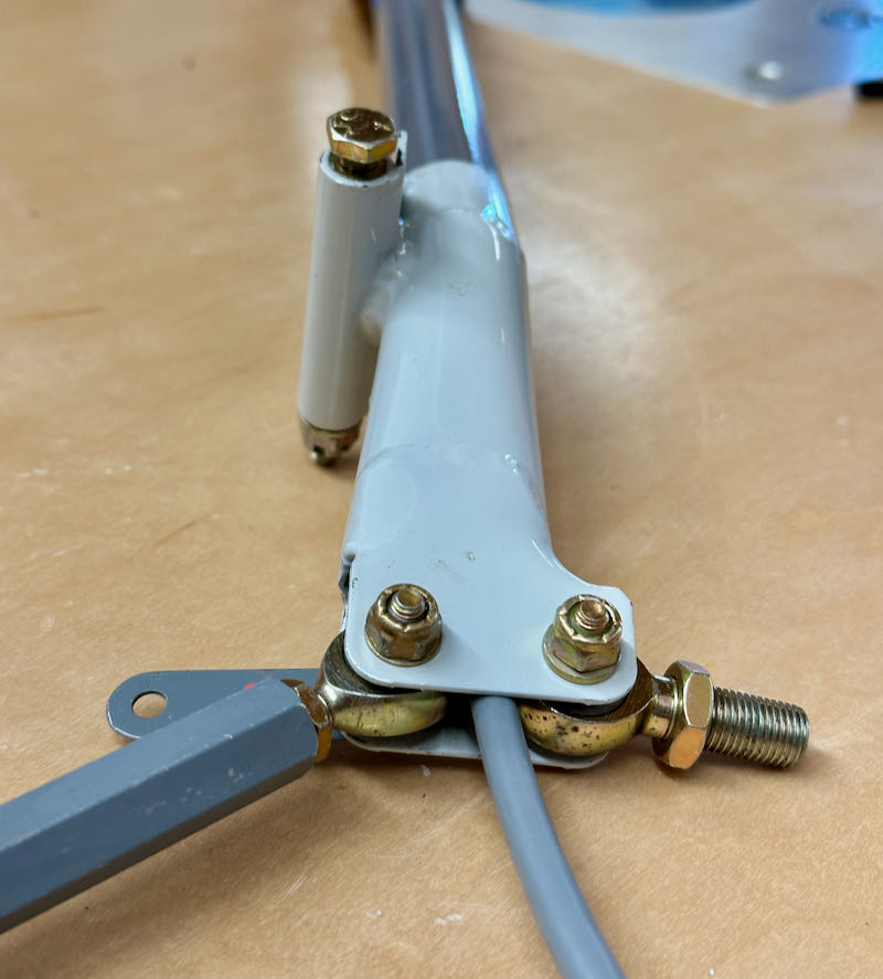
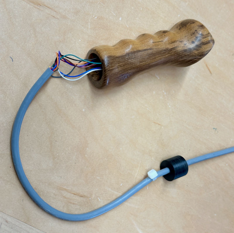
On to the wiring… instead of using standard aircraft wire here, I sourced some ultra-flexible cable intended for industrial robots. It is as bendy as a wet noodle, even though it has a total of nine conductors inside. It is also only 1/4" in diameter, which allows it to exit the stick tubes by passing down through the pushrod bearings:

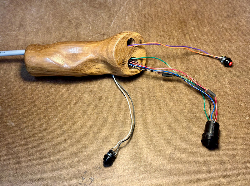
This stuff is rated to withstand ten million flex cycles, so it ought to survive in my airplane just fine. I soldered the 24-gauge wires in the cables to the switches that live on the stick grips:

I'm using Otto P7 milspec switches for the autopilot disconnect and radio PTT buttons, and they have a very satisfying and expensive-feeling click action:

I didn't want to have to worry about these tiny wires getting pulled loose from the switches, so I fabricated some simple strain relief devices that live inside the stick tubes. Each one is nothing more than a close-fitting Delrin bushing and a zip tie that stops the cable from being pulled all the way out the bottom:

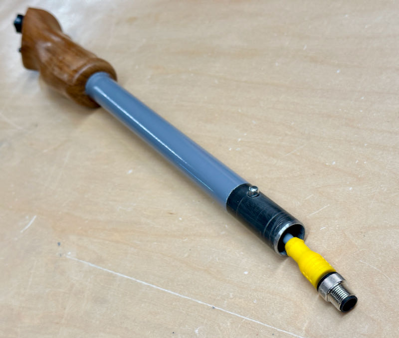
The flex cable assembly I bought had a pair of M12 connectors already installed. I had not encountered this type of connector before, and I'm glad I didn't have to solder or crimp them because they are really small. So small that they can fit inside the passenger stick tubes, which combined with the secure threaded and locking connection method makes them an ideal choice for the passenger side:

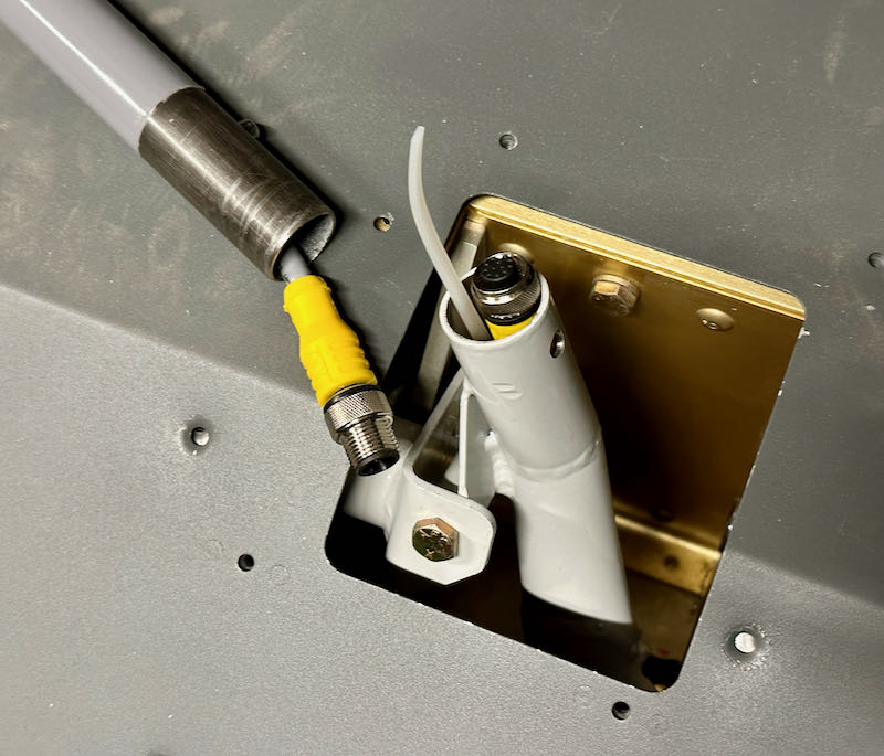
The mating connector lives inside the pivoting part of the passenger stick. The little zip-tie tail is there so I can fish it out if it falls down inside the socket:

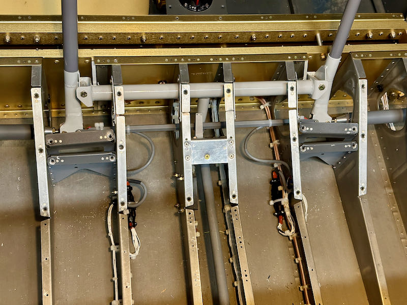
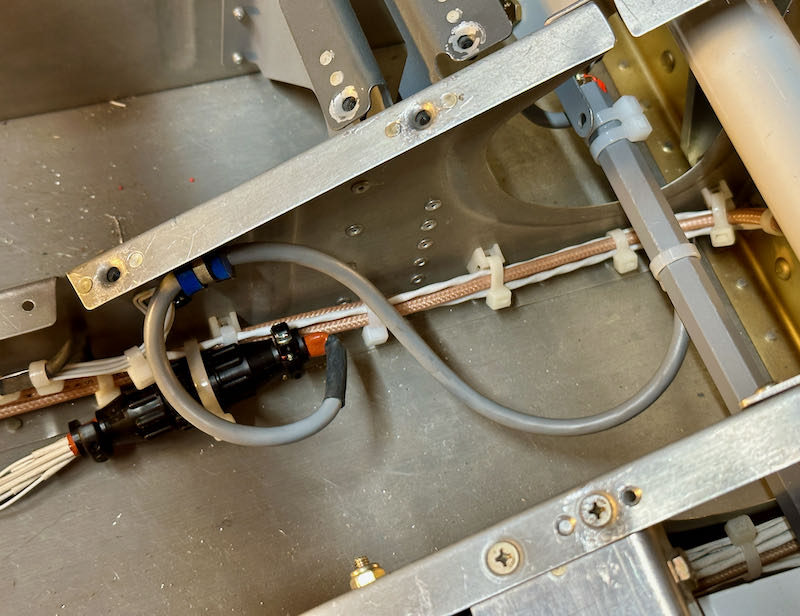
Here's an overview of how I routed the cables from the sticks and connected them to the aircraft wiring. The flex cables are zip-tied to the F-665 pushrod, and a loop of cable is provided that's just slack enough to allow easy flexing but not so loose that the cable can chafe against the fuselage structure:

Here's another view showing how each side is arranged. The flex cable is secured at the stationary end by an adel clamp, and connects to the fuselage wiring via a 9-pin CPC connector:

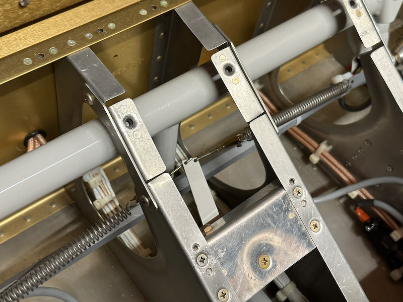
With the control sticks completely installed at last, I reconnected the aileron trim springs:

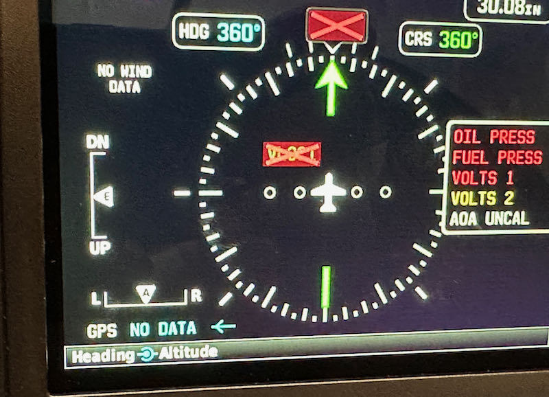
I did a quick calibration of the aileron trim position sensor, resulting in one less red X on the screen:

As the final step, I attached the stick grips to the tubes using the manufacturer's recommended method of simply gluing them in place with clear silicone. To do this correctly, I had to install the seats and sit in the plane to judge the proper rotation angle while gluing the grips. Did I make airplane noises? I'll never tell…