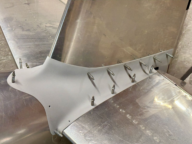
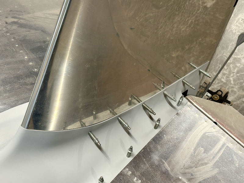
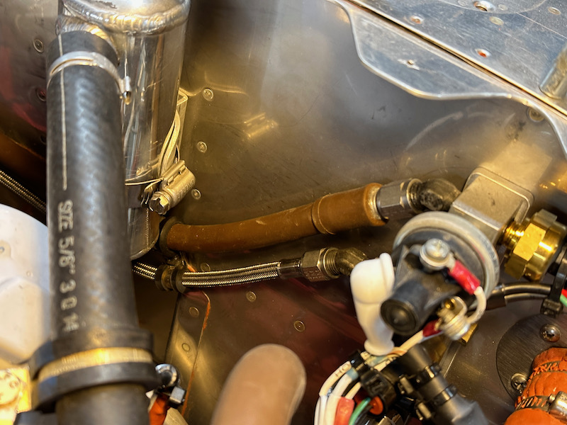
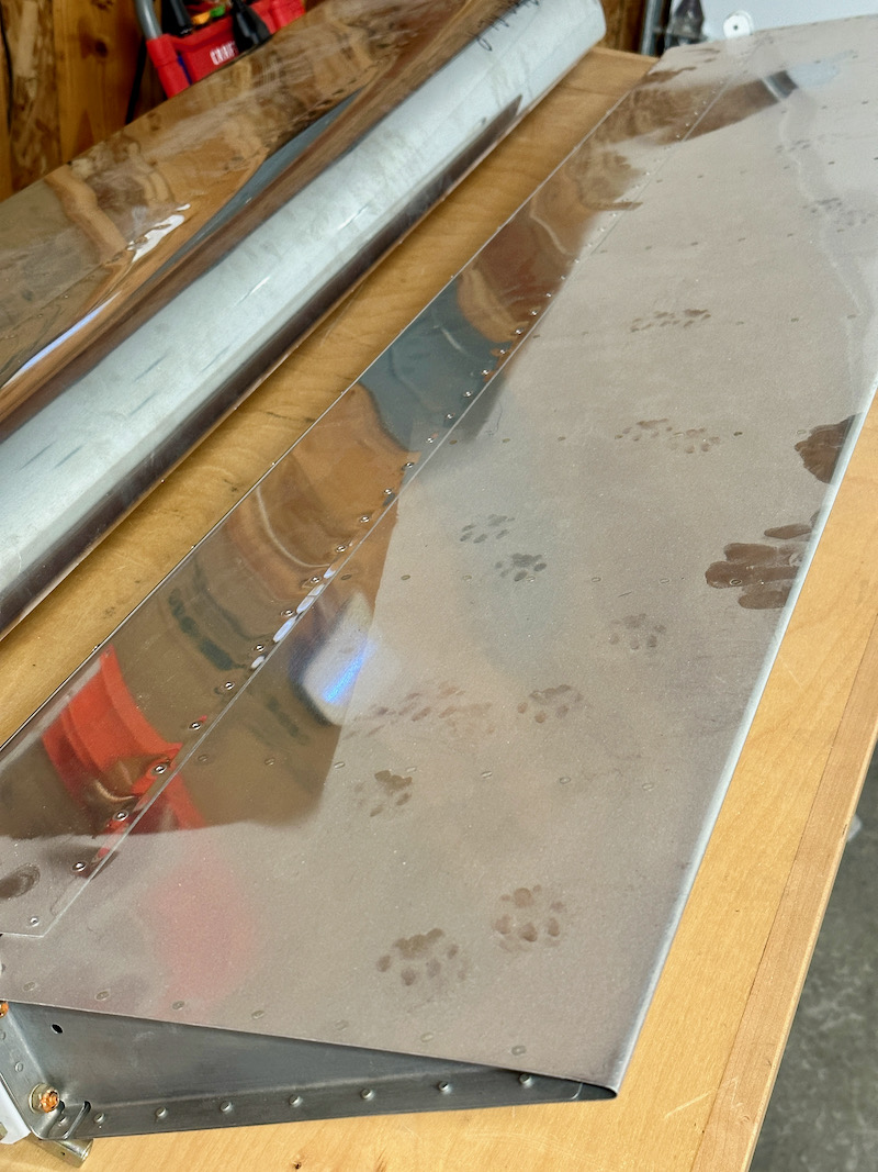
I brought the ailerons down from the attic and cleaned off the worst of the dust – but not before being perplexed by the critter tracks I found. Let's hope that happened during the time I had them stored in a neighbor's hangar:
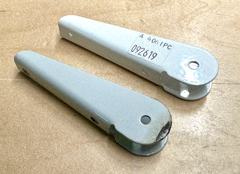
One of the steel hinge brackets had developed some rust, and though I could have cleaned it up and repainted it, I decided it was easier just to replace it with a new one:
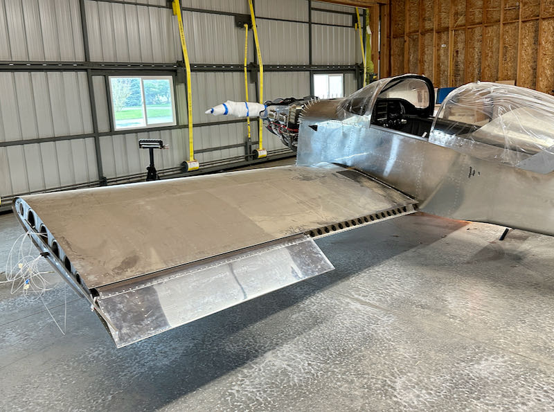
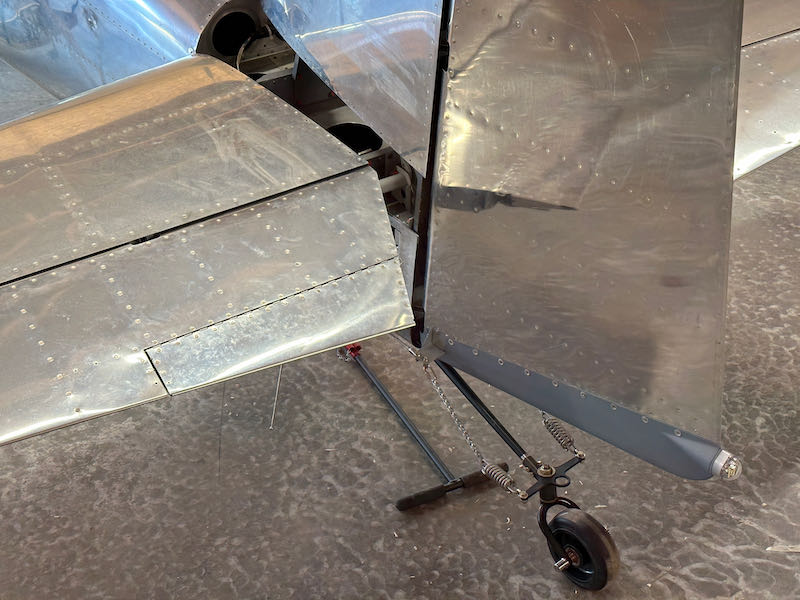
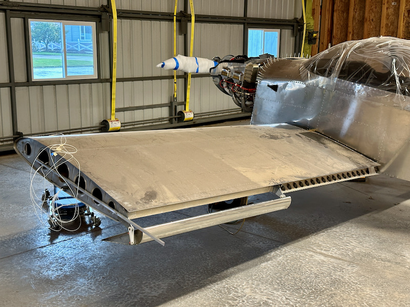
With all that cleaned up, I proceeded to hang the ailerons on the wings:
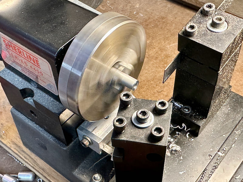
I made the required hinge spacers on my little lathe, which is great for this kind of job:
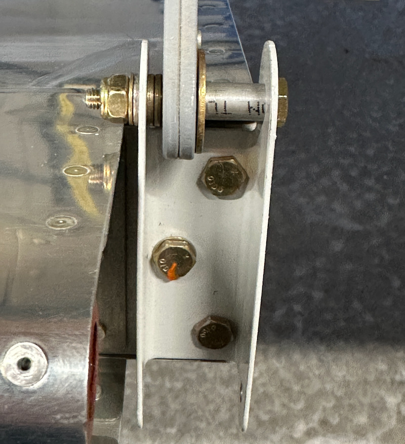
This is what the hardware stack-up for the outboard hinge brackets looks like. (Note: many of these photos taken during the test-fitting process show loose fasteners and non-aviation hardware. I'll fix everything up properly when I'm done fiddling with things.)
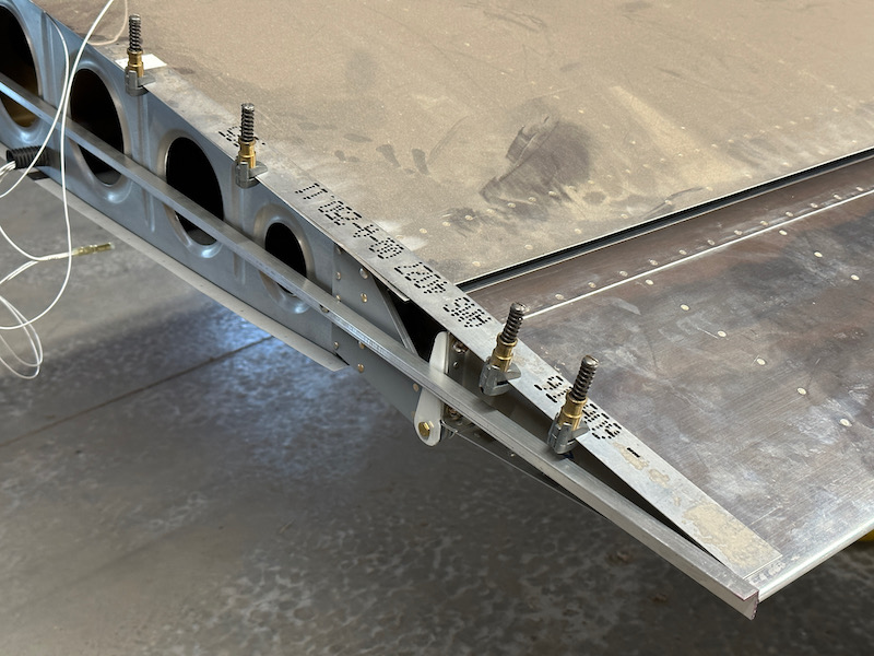
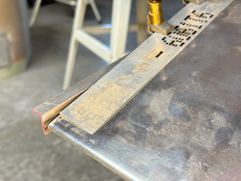
I made a set of alignment tools out of hardware-store aluminum and bolted them to the tip rib. It helps to put some spacers between the angle and the rib (I used the lathe again) to prevent it from being bent by the outboard hinge bracket. That would throw off your aileron alignment and lead to problems later. You can also see here how I am holding the aileron in place with a strip of scrap aluminum and some cleco clamps:
This is an easy way to solidly hold the ailerons in the right orientation (tip aligned between the blue lines) while I work on other parts of the flight control system
This photo is looking up through the outboard access hole in the left wing. The W-818 pushrod runs from bottom to top on the left side, and the W-716 pushrod goes off to the left. Visible in back is the W-730 alignment jig holding the bellcrank in the right position. The idea here is that you use jigs to align the bellcrank and the aileron, then adjust the W-818 pushrod to connect them.
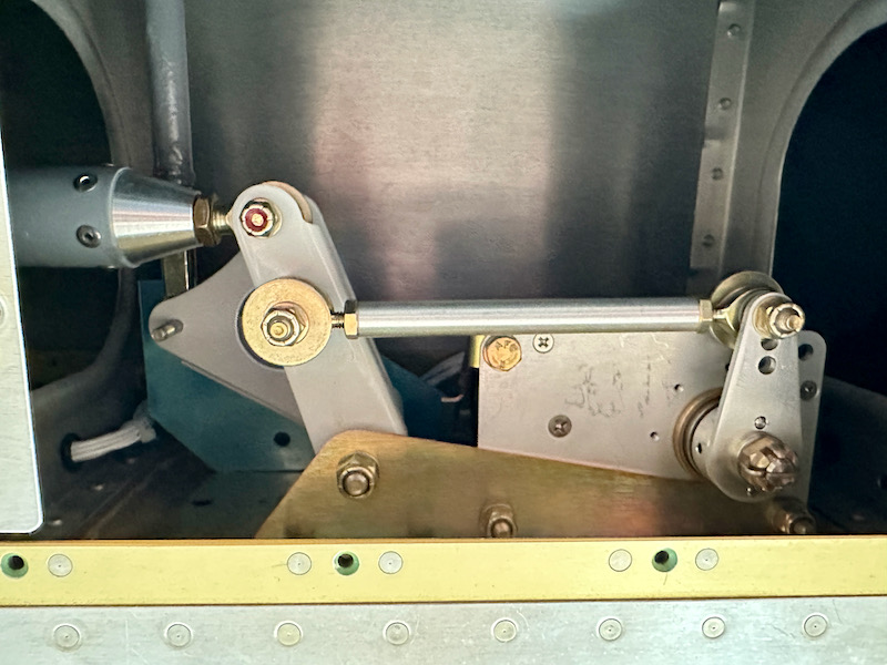
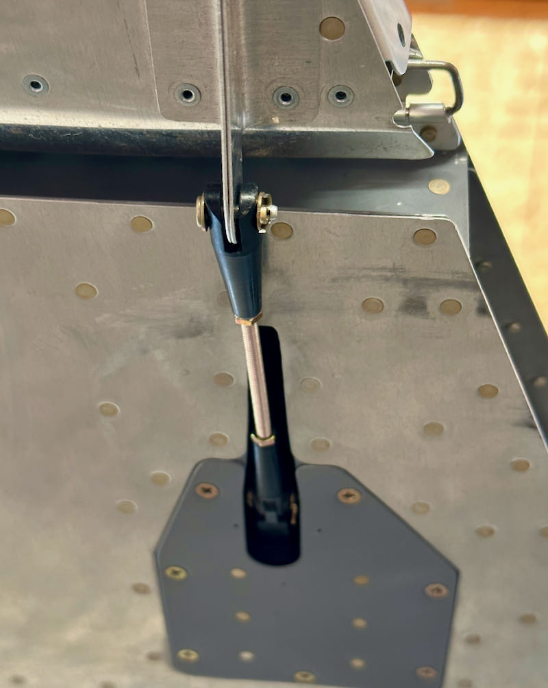
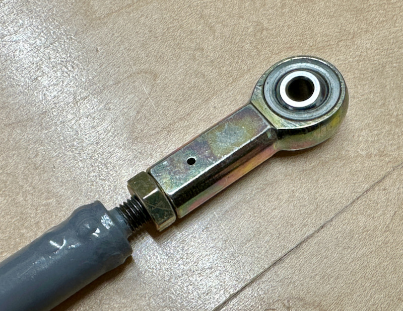
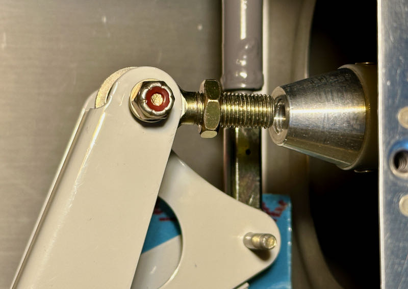
Although I fabricated my W-818 pushrods using the dimensions shown in the plans, they ended up slightly short. Judging from the many similar forum posts I've read, this is a common occurrence – it would be best to make them 3/16" or even 1/4" longer, material permitting. I solved the length problem here by switching the jam nuts to AN315s, which are 1/16" thicker than the default AN316s (a modification approved by Vans customer support). This ensures that no matter how the pushrod tries to unscrew itself, the worst-case rod end bearing will still have more than the minimum amount of thread engagement.
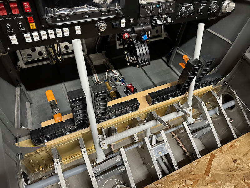
Inside the cockpit, I built a temporary jig to align the control sticks vertically, using a collection of woodworking squares which are screwed to a board clamped to the spar:
I maneuvered the W-716 (transverse) pushrods into the wings, adjusted them to fit between the control sticks and the aileron bellcranks, and then got a rude surprise. Although I built them exactly to the length specified in the plans, they are way too short, and will allow the rod end bearings to unthread themselves – an obviously unacceptable condition:
Judging from the many forum threads on this topic, this is another well-known plans error that has caught plenty of other builders just like it caught me. How incredibly aggravating. So now I'm on the hook for $100 worth of parts and the time required to build a new set of pushrods. At least nowadays I'm close enough to the factory to save on what would otherwise be the exorbitant cost of shipping long pieces of tubing. The new parts will be 7/16" longer than the plans dimensions:
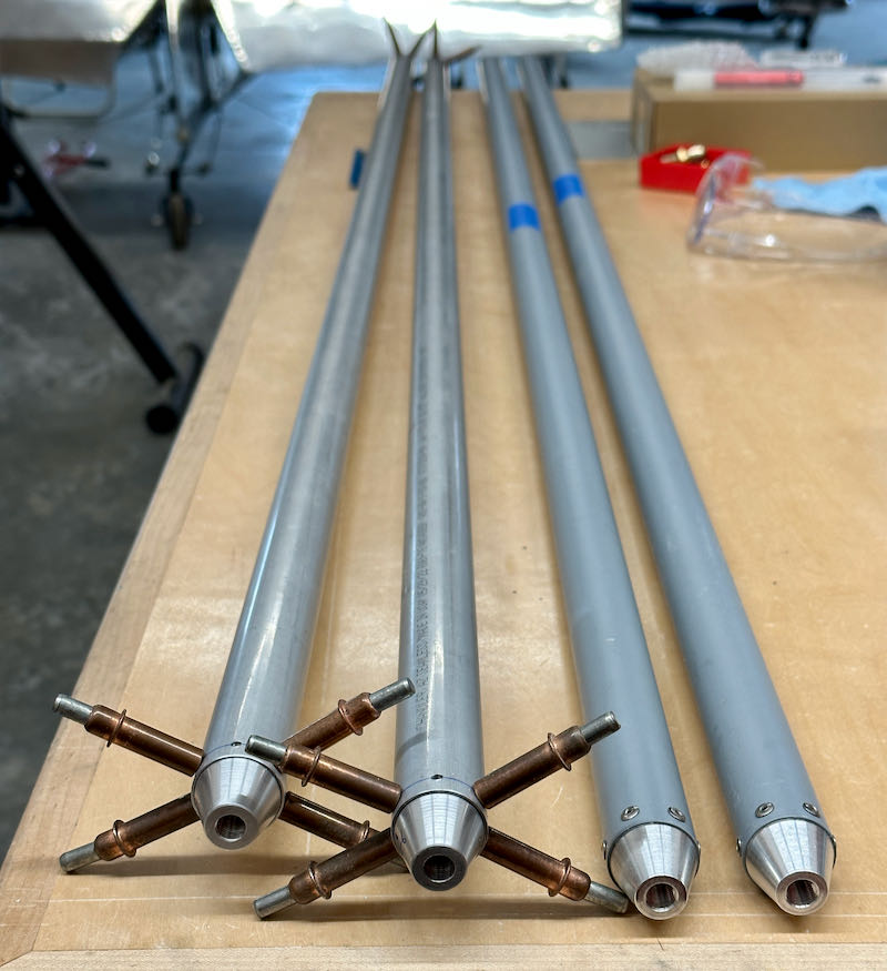
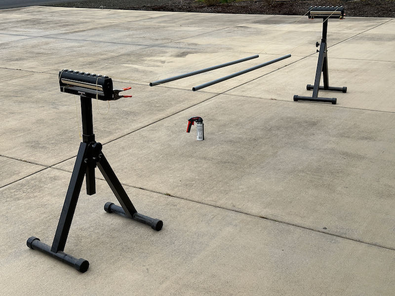
These aluminum pushrods are trivial to build, but they end up taking a while due to all the priming required, especially in the winter. I flooded the interior of the tubes with 7220 spray primer and allowed them to dry for several days, then suspended them on strings and primed the outside:
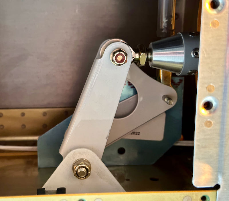
Finally I riveted on the end caps, inserted the bearings with their jam nuts, and slid the new pushrods into the wings. The result is a perfect fit that can't possibly come undone. In retrospect I could have made these 3/8" longer rather than 7/16", but this will work fine. This photo shows that there are still plenty of threads engaged in the worst-case condition where the other end is screwed all the way in:
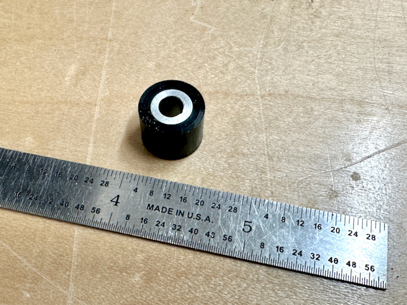
With the left and right ailerons finally connected together properly, I was able to fabricate the control stops. The plans call for a set of aluminum angle pieces riveted to the hinge brackets, but I wanted to try the popular method of using plastic bushings on the pushrod attachment bolts instead. I happened to have some black Delrin stock on the shelf, so I turned a pair of 1/2" diameter bushings with an aluminum spacer in the middle to handle compression:
This is what the aileron stops look like when installed – the black Delrin ought to be good for UV resistance:
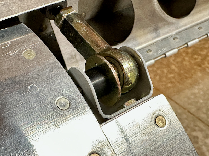
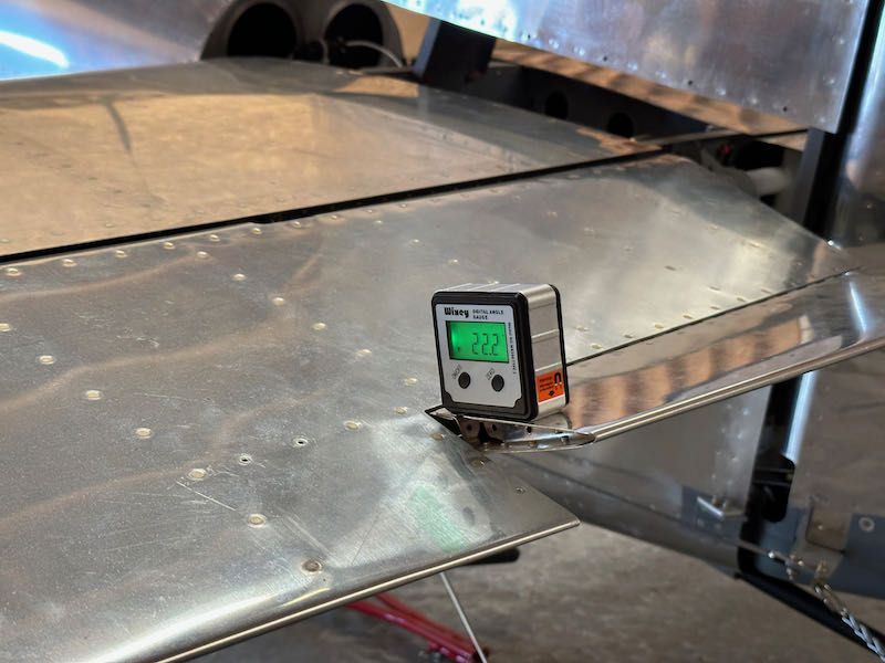
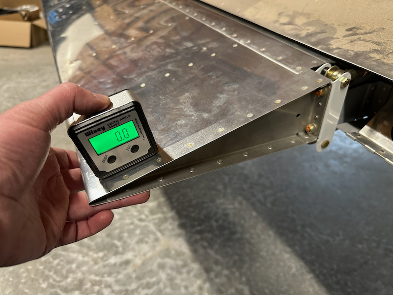
It turns out that – for my airplane – the 1/2" diameter stops are an ideal size. To check the aileron travel I aligned the ailerons with the tip jigs and set my digital angle gauge to zero with the ailerons neutral:
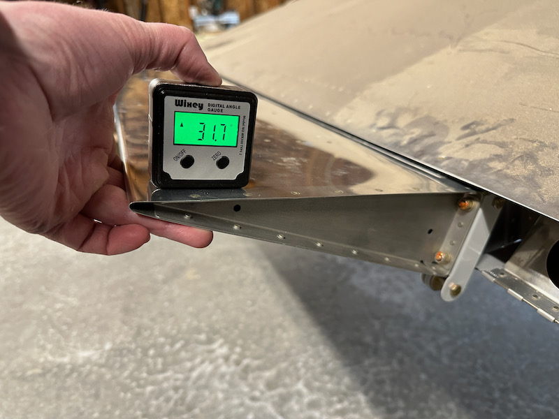
The ailerons on both sides hit the up-stop just shy of the 32º maximum limit specified in the plans:
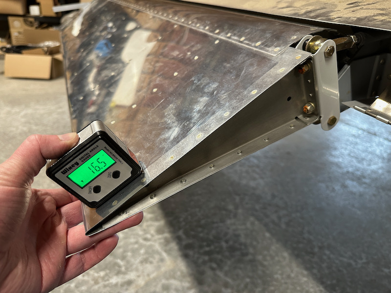
Similarly, the amount of down-travel is well past the minimum and just under the 17º maximum:
This also gives me my first chance to evaluate the total movement range of the control sticks inside the cockpit. Happily, neither stick comes close to hitting the throttle quadrant, which had been a concern:
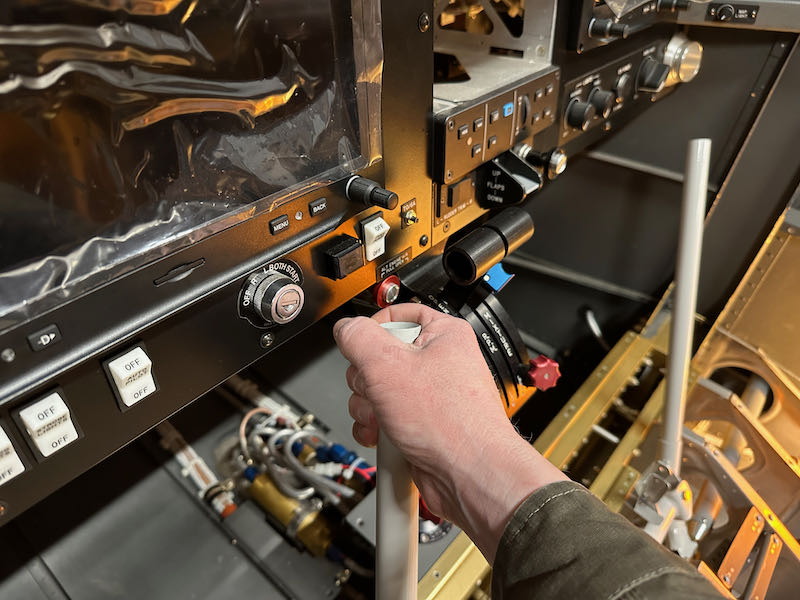
Similarly, opposite aileron travel provides plenty of clearance between the sticks and anything nearby. I'll still have to trim these shorter to accommodate my stick grips, but it's good to know what I'm working with:
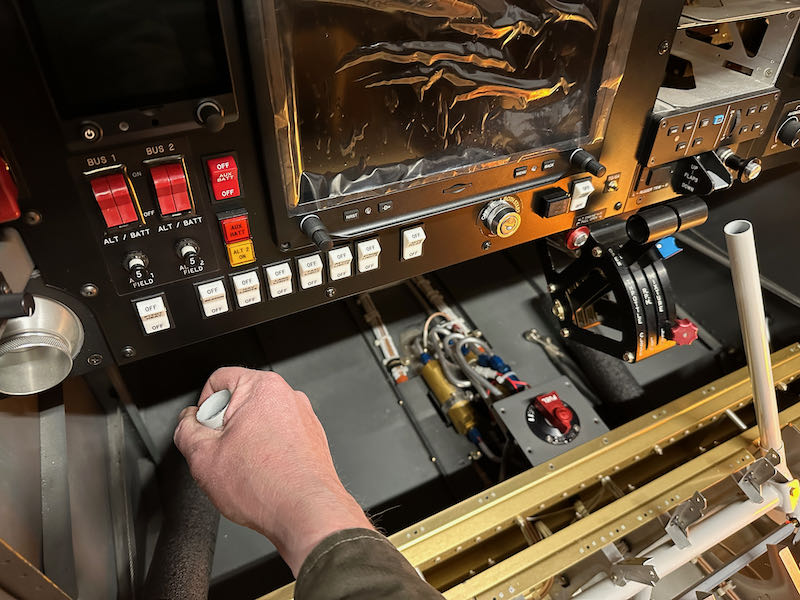
I haven't torqued all the fasteners yet, as I will probably have to remove the sticks at least one more time, but for now all the primary flight controls are hooked up and usable – a great milestone:
