Archive for the ‘Electrical/Panel’ Category

Map lights

Sunday, February 28th, 2021

Here's some more info on the little cockpit spotlights seen in the previous post. These little swiveling LED lights are made by Oplite, and they seem a bit expensive for what they are… but then again at least I don't have to buy the PMA version, which is 3x the money for the same product plus some magic paperwork that makes it legal to install in your certified airplane.

I mounted them to the roll bar weldment with a trio of tiny 4-40 nutplates. The screws shown here are just for test-fitting – in the final installation they need to be much shorter since the space between the roll bar and the skin is very limited. I also later reversed the plastic snap bushing for the same reason.

Here's what the hidden side of the roll bar looks like prior to installation of the skin:

To run power and ground to each light I used pieces of black nylon tube as conduits – it's actually the same pitot/static tubing material I already had laying around. There's a small notch in each corner of the panel to allow the wires to pass through.

I left the wires long enough to solder to the pigtail on the light with the skin installed, which theoretically should allow me to remove and replace it without major surgery if it ever burns out:

Then I pulled the excess wire through the tube and bundled it up behind the panel, and voila, a clean looking installation with hidden wires:

These lights are controlled by dimming knobs located on the F-721A canopy decks. They're also connected to the aircraft's auxiliary battery, which also allows them to double as emergency cockpit lighting.

Defrost fans

Saturday, January 9th, 2021

I bought a pair of low-power 60 mm computer fans, which I plan to use for moving warm air from under the panel and blowing it on the base of the windshield:

I laid out a simple doubler on a scrap of 0.032" aluminum, then made a second one by match-drilling with the first:

I figured out where I wanted to mount the fans, then drilled the doublers to the skin in the correct location:

I enlarged the center holes up to 5/8" with the doublers clecoed in place:

The 5/8" hole allowed me to use my instrument hole punch to make 2.25" holes for the fans – coincidentally that's very close to 60 mm. I love this tool, it's massive and does its one job perfectly (and was made in the US!).

Deburred, dimpled, and back-riveted the doublers to the inside of the skin:

This is what the fans look like when affixed with some temporary hardware. I need to get the correct screws to use here, and also make or purchase some kind of cosmetic cover to dress them up a bit.

This picture shows where the fans are located in relation to the rest of the panel. The left-side fan will be easy to reach from underneath, and the right-side fan can be accessed by removing the audio panel and reaching up through the hole in the top of its tray.

I still need to crimp some connectors to plug these fans into the existing wiring, but that can wait till the next time I have the crimping tools out.

Annunciator lamps

Friday, January 1st, 2021

I received a baggie of engraved annunciator lamp diffusers from Aircraft Engravers. These are for EAO Series 31 lamps, which are available from the usual suppliers (as well as Aircraft Spruce, for a lot more money). The diffuser piece sits between the bulb – or LED, in my case – and an interchangeable colored lens.

The lamps are all controlled by the annunciator controller board I built years ago. I recently dusted it off and finished writing the software for it, so it's good to go now. It handles lighting the various lamps in response to external inputs, dimming, and the press-to-test function.

Across the top of the panel on the pilot's side is a row of lamps, showing an oil pressure warning (driven by a separate pressure switch), the master caution/warning annunciations from the G3X system, and a press-to-test button. The latter has a smoked lens on it so it presents as more or less plain black when not illuminated.

Next to the bus power switches there is a warning lamp for aux battery voltage, and a caution lamp showing that the bus 2 alternator is under load (i.e. the main alternator has failed).

At the bottom of the panel is an annunciator to remind me that the fuel pump switch is on. This has a blue LED but a smoked lens, so it appears dark when off.

Here's what they all look like when lit, although the camera struggles to make sense of the contrast with the LEDs illuminated:

As the controller software stands now, the press-to-test lamp is illuminated until you press it the first time per flight. That way I won't have an illuminated test button in my face all the time, but it will be lit up during startup, when "annunciator test" will be an item on the checklist.

Here's a closeup of the top row of lamps lit up. I'm pretty happy with the way these turned out.

Finished panel installation

Saturday, November 21st, 2020

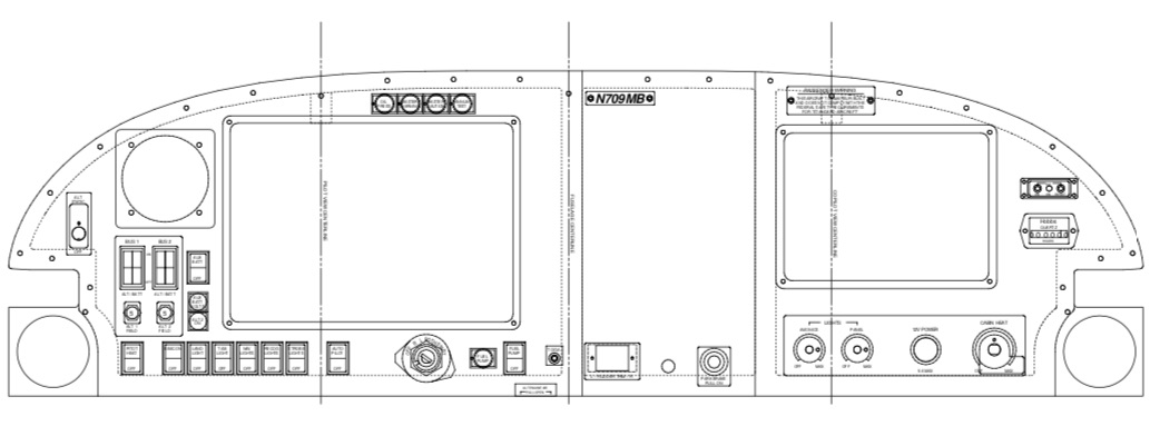
Before I moved across the country and put my project on hiatus, I had been working on a partial panel redesign to incorporate G3X Touch displays. I left the radio stack alone, but I had Steinair cut me two new pieces for the left and right halves of the panel so I could change the displays around. The main change was to replace my previous GDU 37x (7" portrait) displays with a GDU 465 and a GDU 450 (10.6" and 7" landscape screens). Electrically everything was nearly plug-and-play, with just a few wires needing to be moved around to accommodate the change from three displays to two. I also took the opportunity to replace the steam gauge backup instruments with a G5 electronic instrument, which is what the round hole on the pilot's side is for.

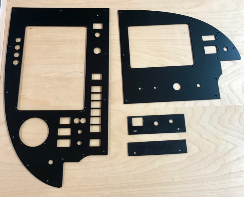
That's the last thing I was working on back in 2015, and more recently I found that I'd left myself plenty of loose ends to tie up, both literally and figuratively. When I finally reached a point where I couldn't proceed any further without having the panel installed for good, I took the pieces to a local powder coat shop to have them finished. It took a while, but I eventually got everything back and looking sharp in matte black:

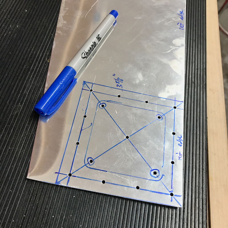
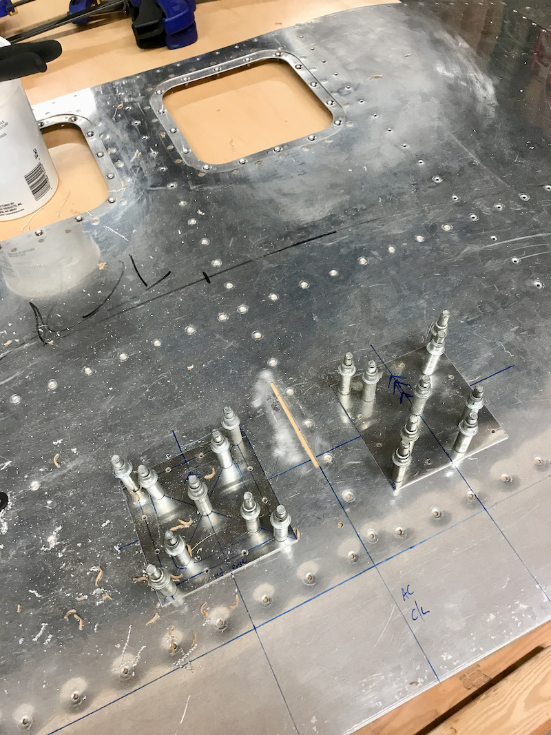
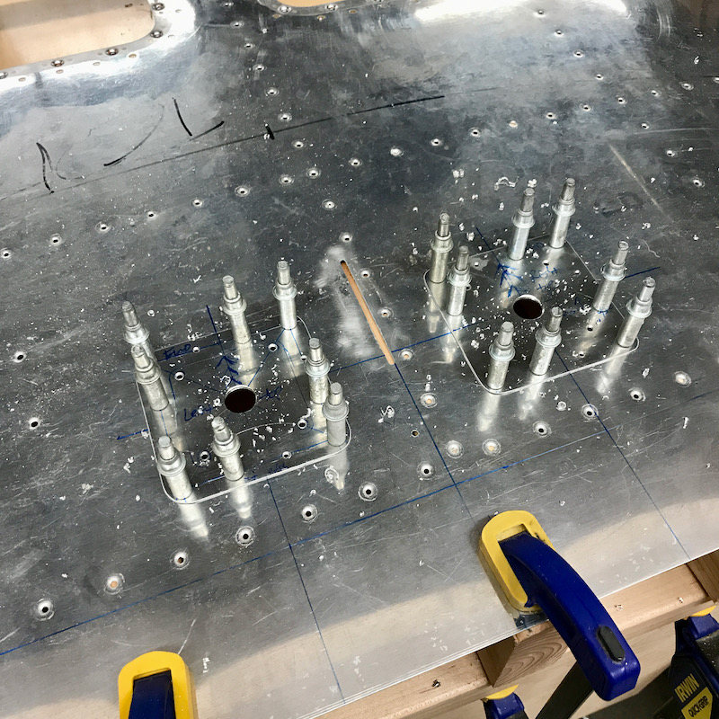
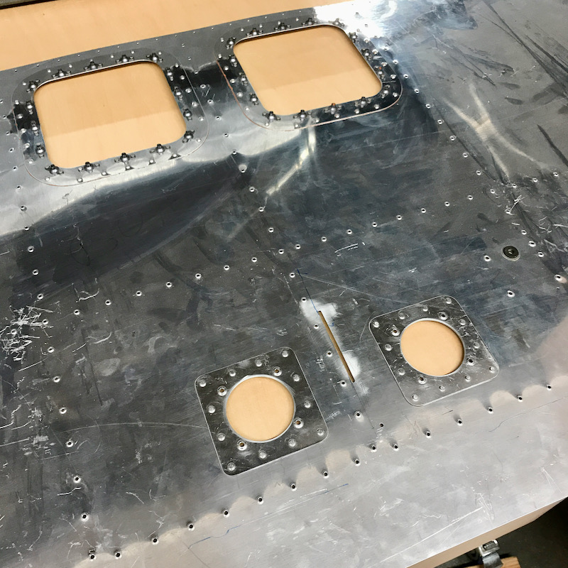
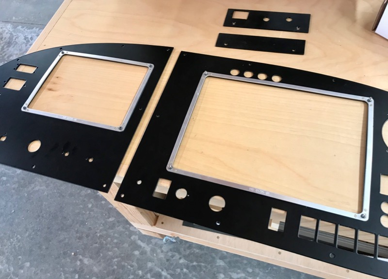
On the reverse side of the panel, I riveted the nutplate rings for the Garmin displays:

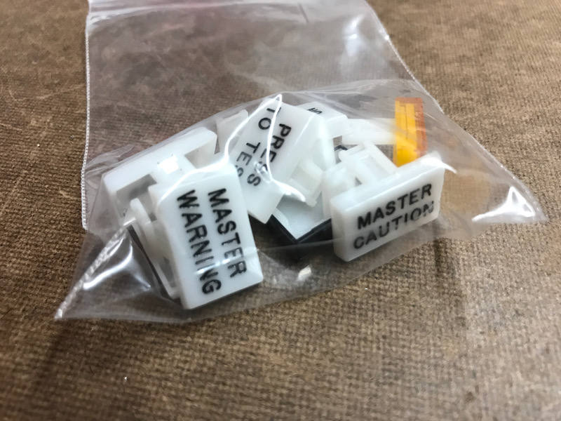
I had Aircraft Engravers make me a set of panel placards in 0.020" Lexan, a few of which are shown here prior to installation. These are engraved and paint-filled on the reverse side, so the markings are protected on the front side and can't be scratched. Should hopefully be tough as nails.

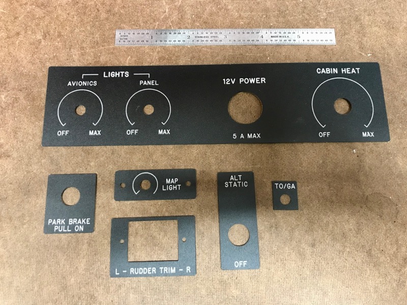
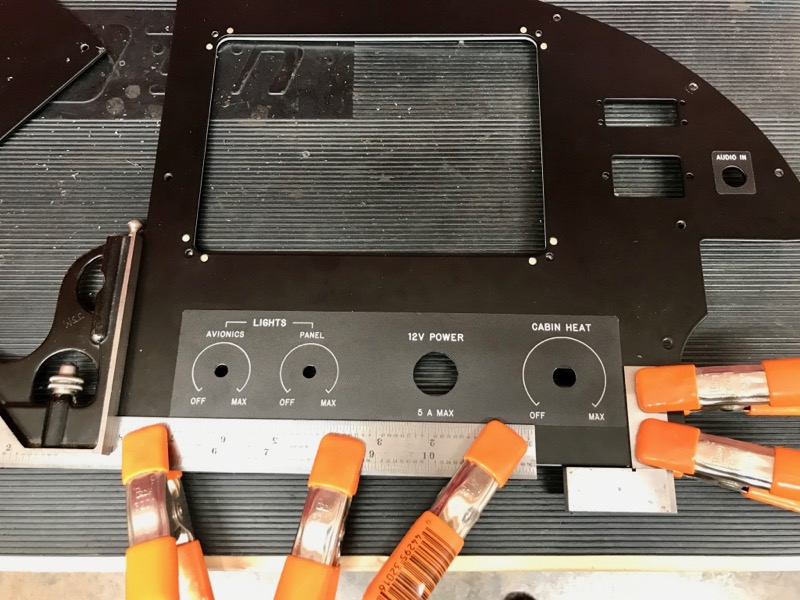
The placards have an adhesive backing – here I'm carefully aligning the biggest placard before sticking it down:

Detail view of the placards on the left side of the panel:

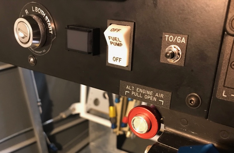
All the controls at the bottom of the radio stack have their own labels:

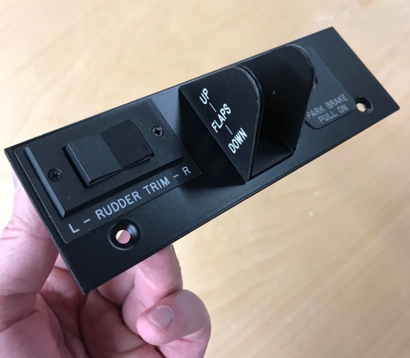
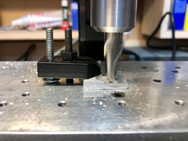
For the final installation, the flap switch spacer needed a bit of thickness adjustment – no problem to shave off a few hundredths on the mill:

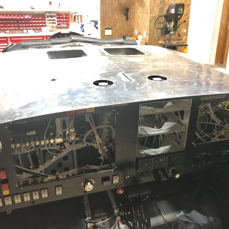
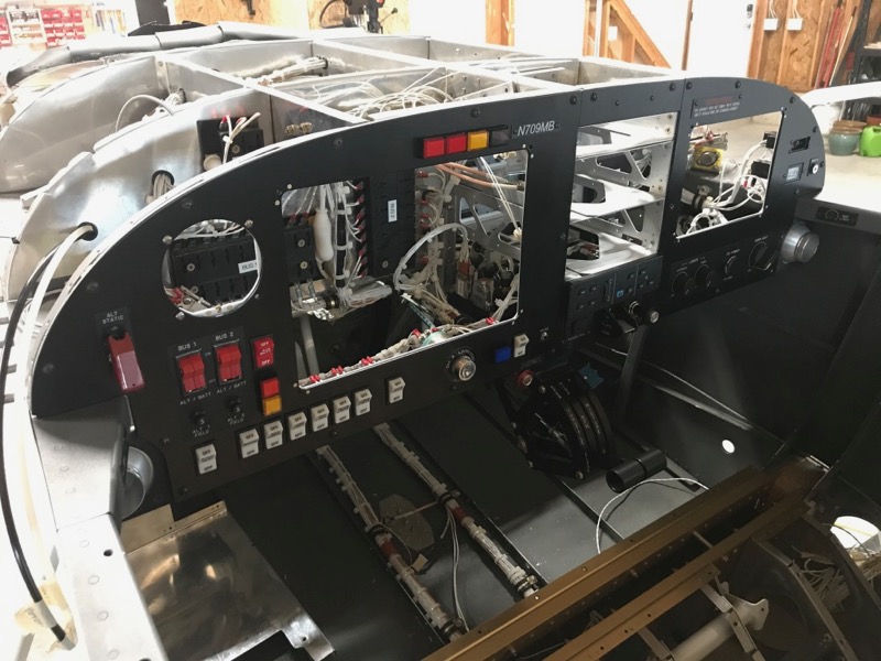
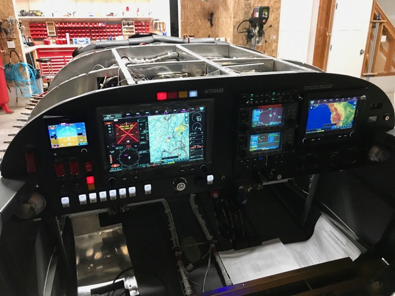
Here's the new panel after being physically screwed in place. As part of this sequence I also had to attach the air vents to the panel, since a few of the vent mounting screws are obscured by the panel plates.

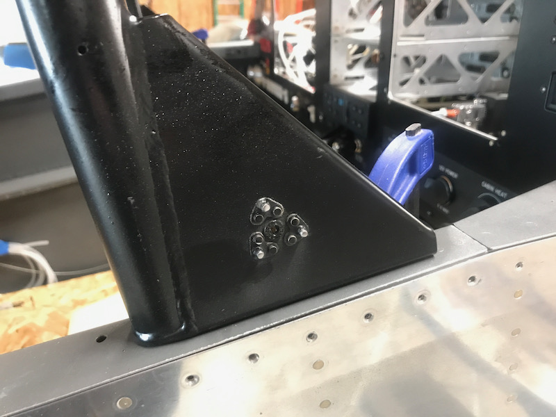
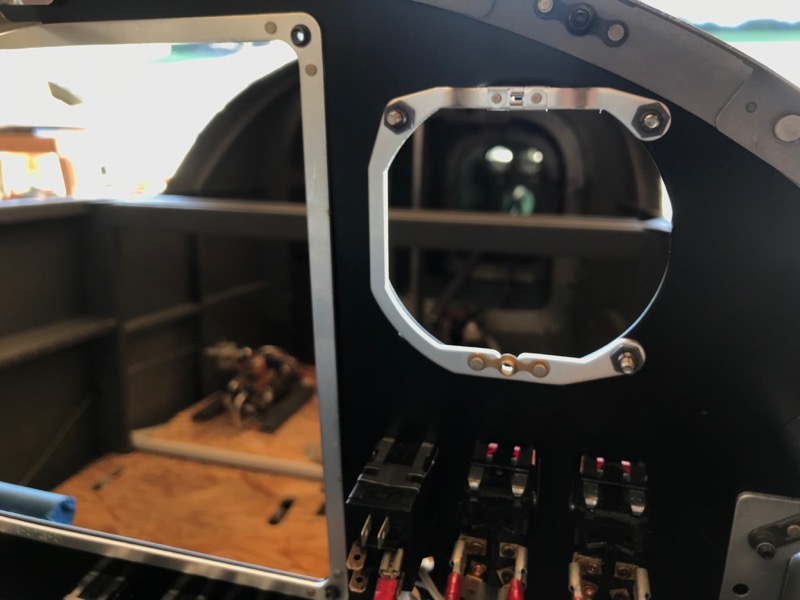
This is the mounting bracket for the G5 instrument. It just barely clears the panel substructure. I'd like to say I planned it this way, but truthfully I just got lucky.

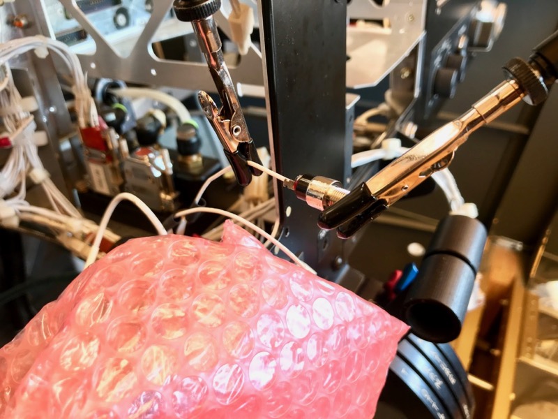
At this point I had a few items in the panel that needed to be installed with soldered connections, including the TO/GA button shown here. I used a pair of magnetic helping hands stuck to a clamp to keep things from moving around while I did the soldering.

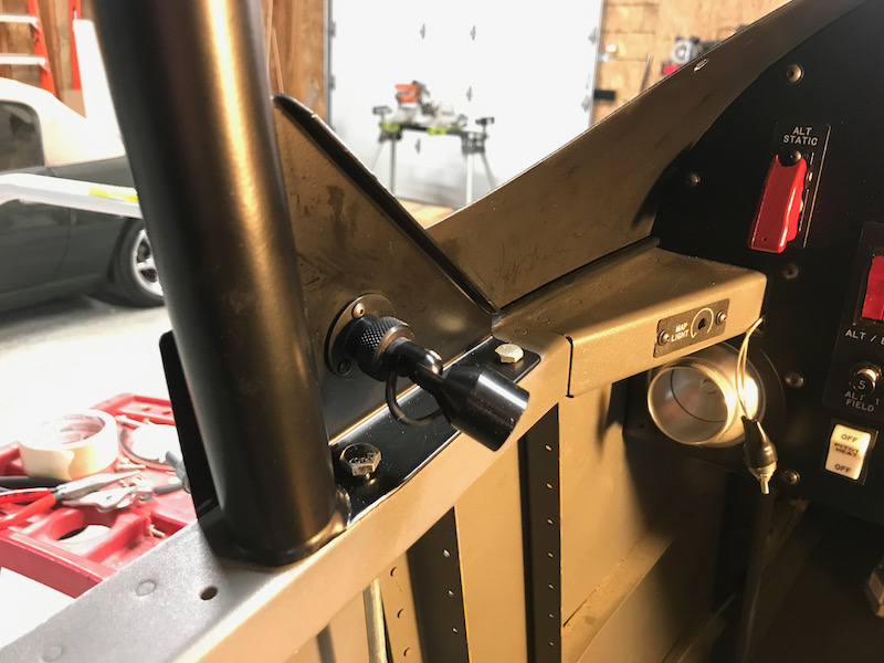
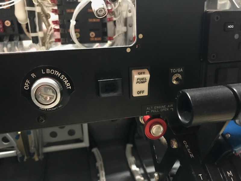
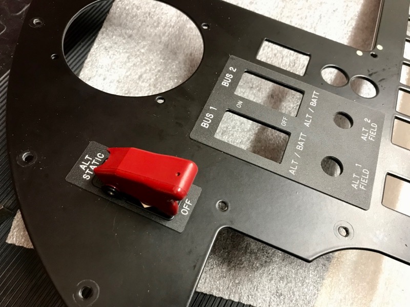
I rethought my previous idea of having a start button on the stick grip – now I have a more traditional ignition/start key in the panel. Here you can also see the placard labels for the TO/GA button and the alternate engine air cable.

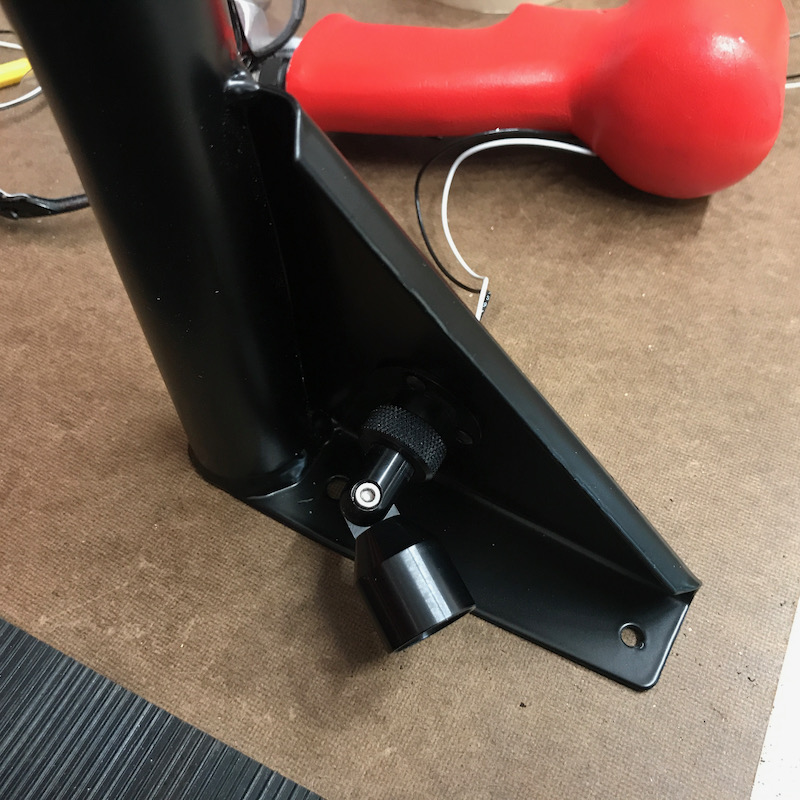
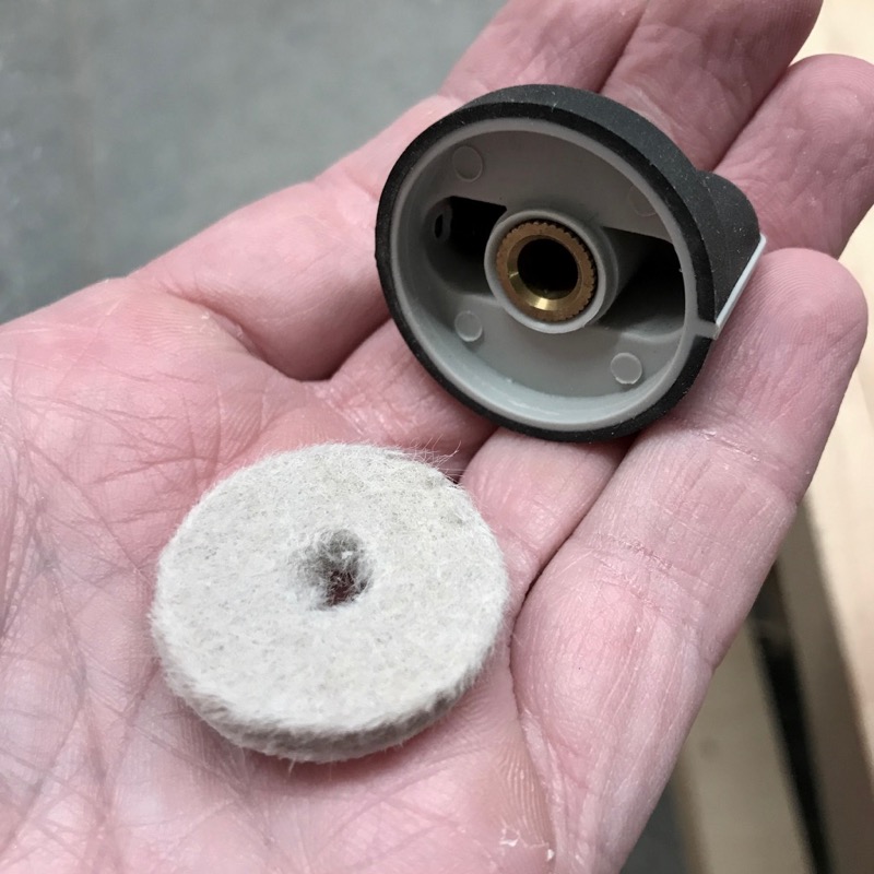
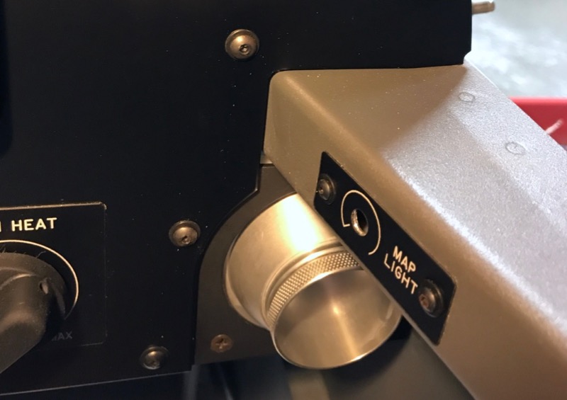
This is the knob for the rotary heat vent control. The knob fits tight to the input shaft, but there's some play in the gear mechanism, which allows the knob to wobble. To fix this, I made a simple friction washer out of thick felt, to fit between the knob and the panel:

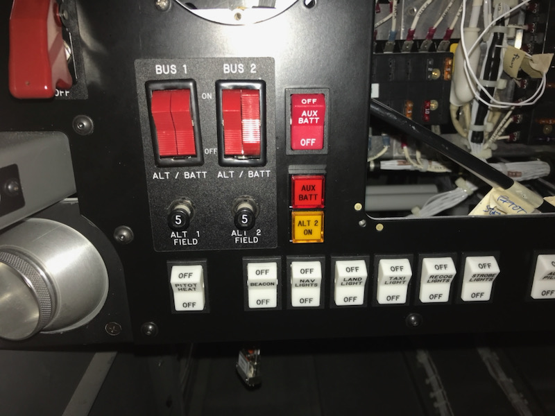
All the knobs and most of the small devices on the right side of the panel are installed here. With the felt washer in place, the heat knob moves smoothly but shouldn't be able to wobble from vibration.

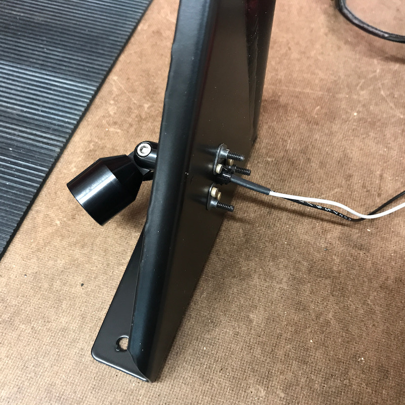
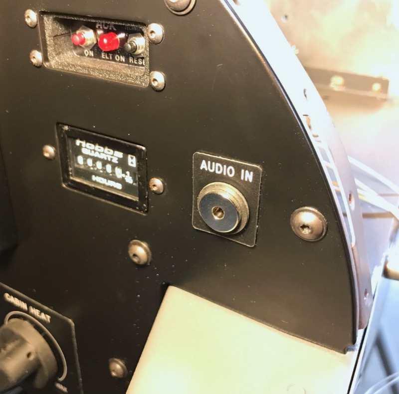
The 3.5mm auxiliary audio jack is soldered in place, with plastic shoulder washers to electrically isolate it from the panel. Here you can also see how I used black oxide coated button head screws and washers to attach the panel and the devices in it:

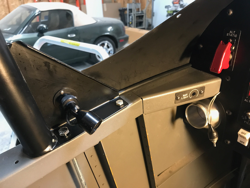
On each side of the cockpit I installed the labels for the map light dimmer knobs, although I'll leave the potentiometers themselves hanging loose until after I set the rivets that live just behind here:

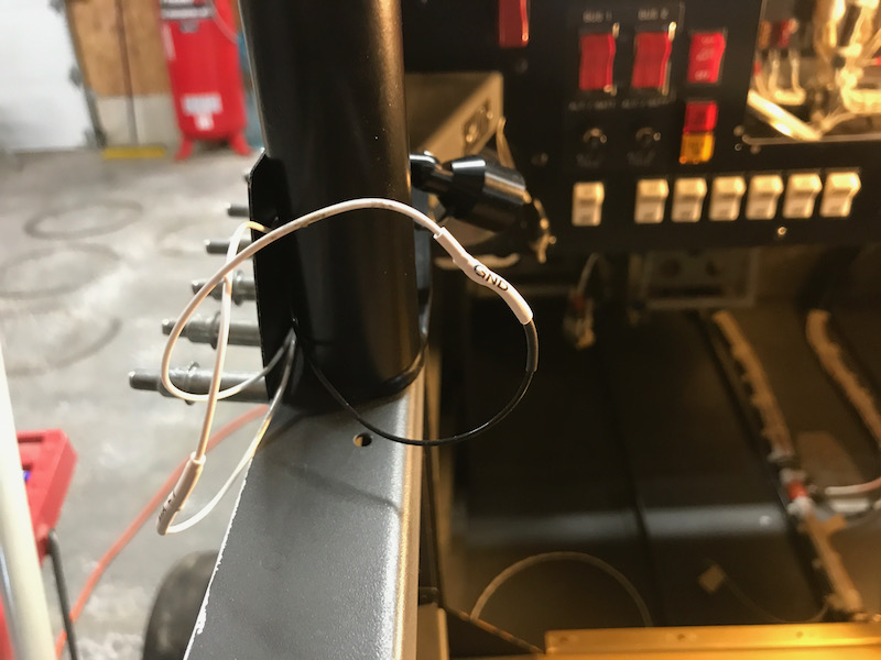
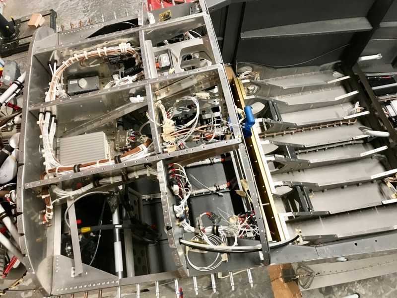
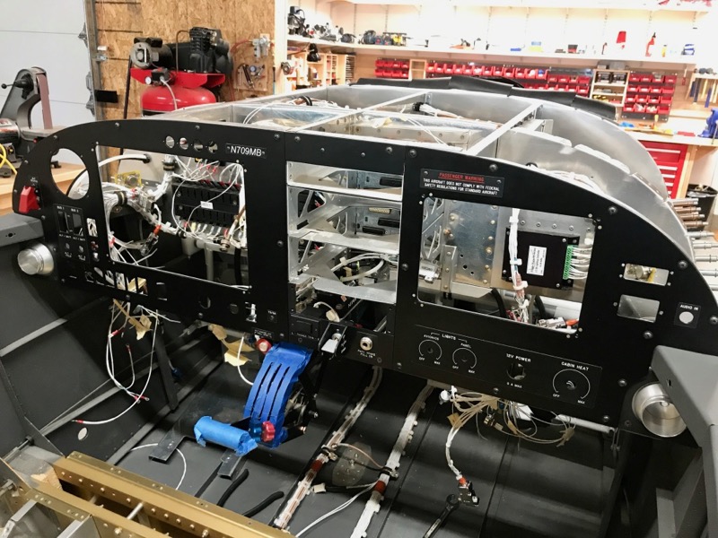
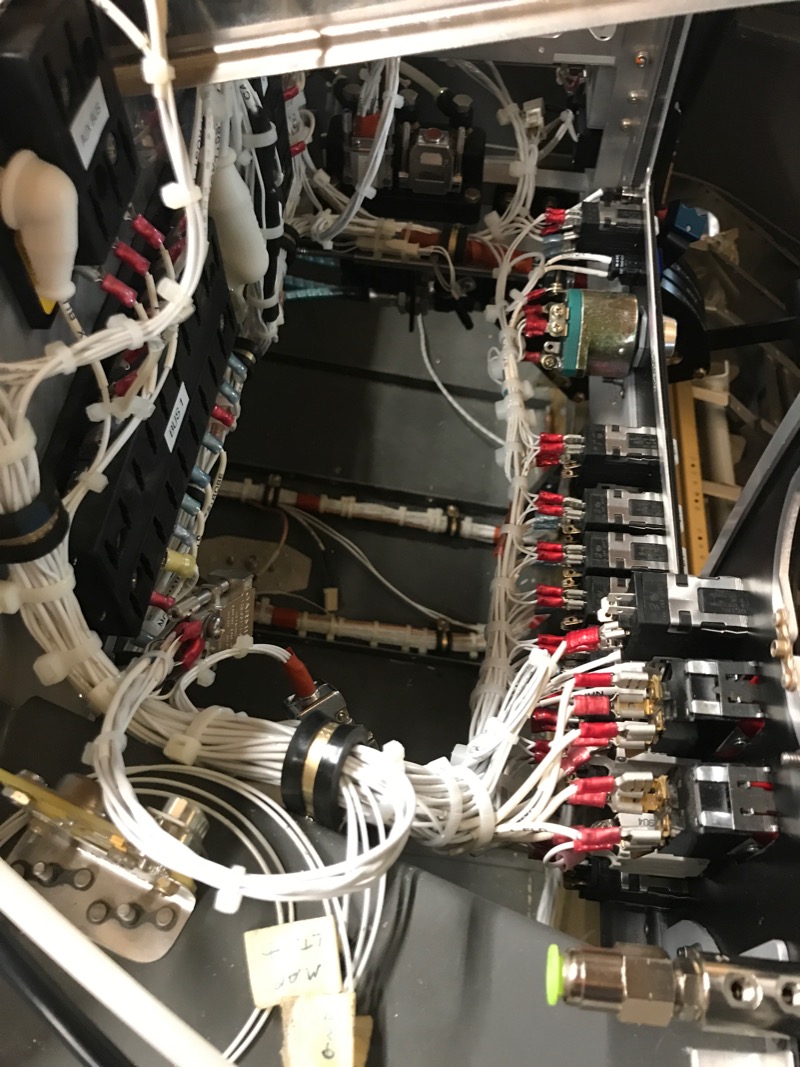
After lots of work tidying up and securing things, here's what the behind-panel wiring looks like. There are still a few loose wires outstanding, waiting for the top skin to be installed, but I think it looks pretty good for now:

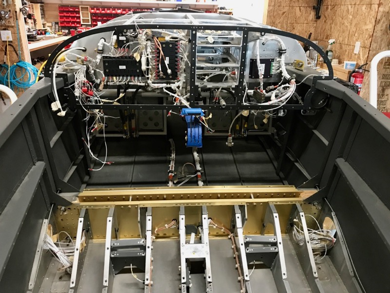
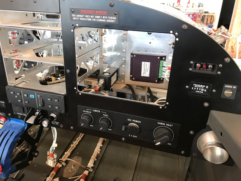
Here's all the non-removeable panel components installed, and the electrical wiring complete and ready for careful testing:

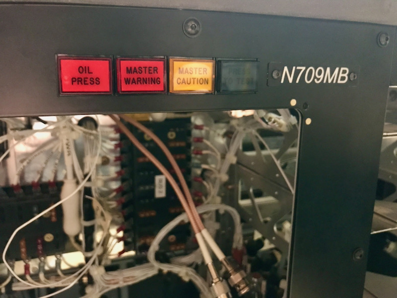
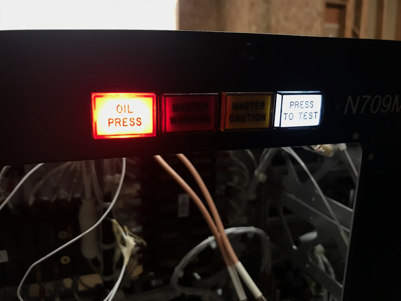
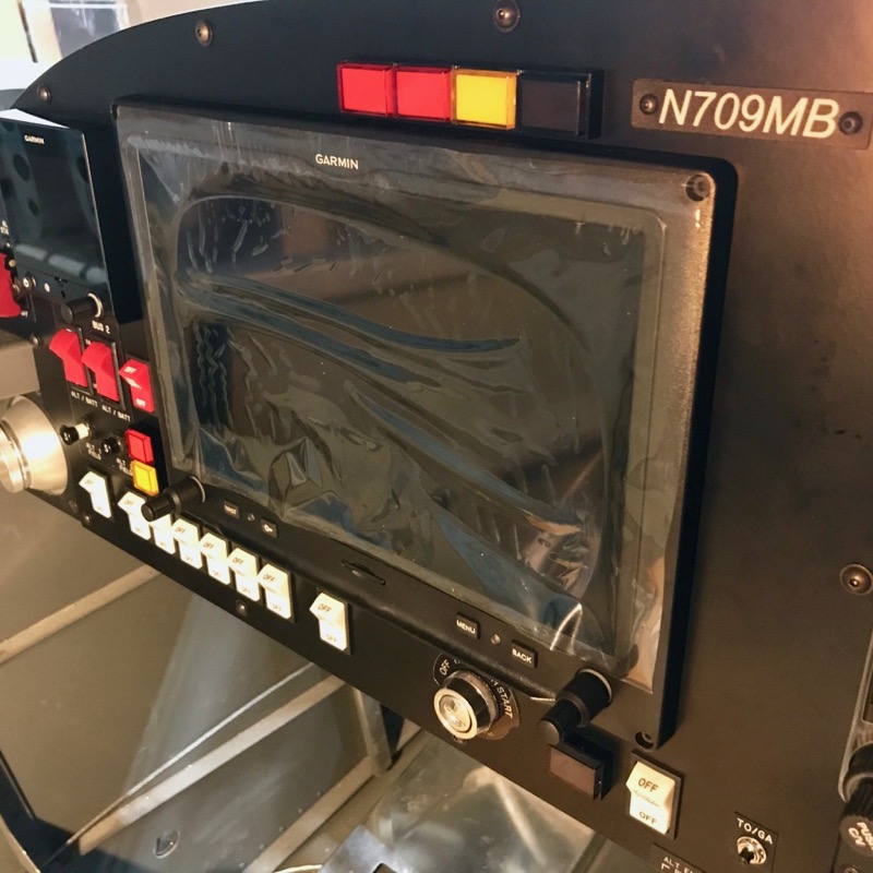
The pilot's display and G5 are shown installed here. There are six annunciator lamps and a test switch in the panel, all of which are waiting for a set of labeled lenses that I've ordered from Aircraft Engravers. So for now they are just pretty colored lights with no text on them.

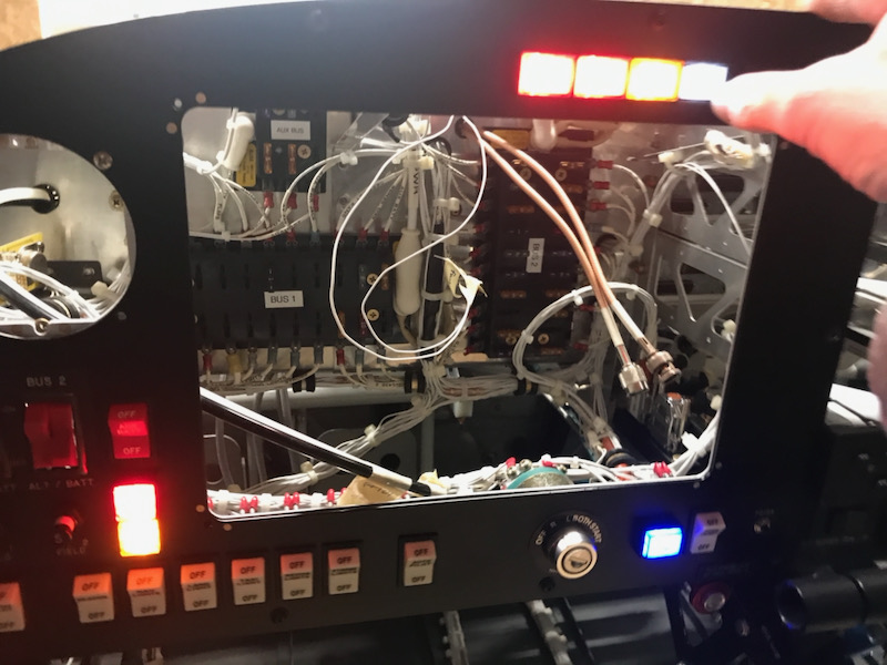
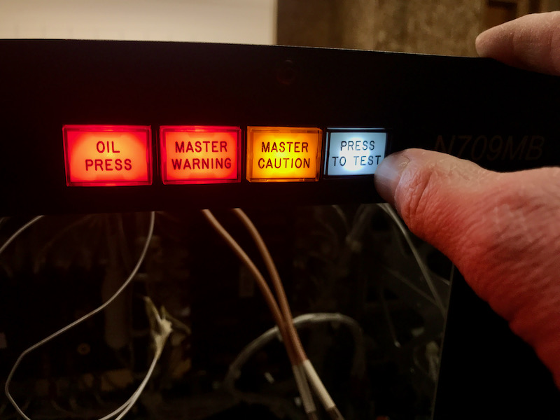
And after some methodical circuit-by-circuit testing, here it is all lit up. Somehow in the past five years I managed to develop one short circuit (in the pilot's right headphone audio channel) but I managed to repair the offending wire and now everything appears to be working as designed.

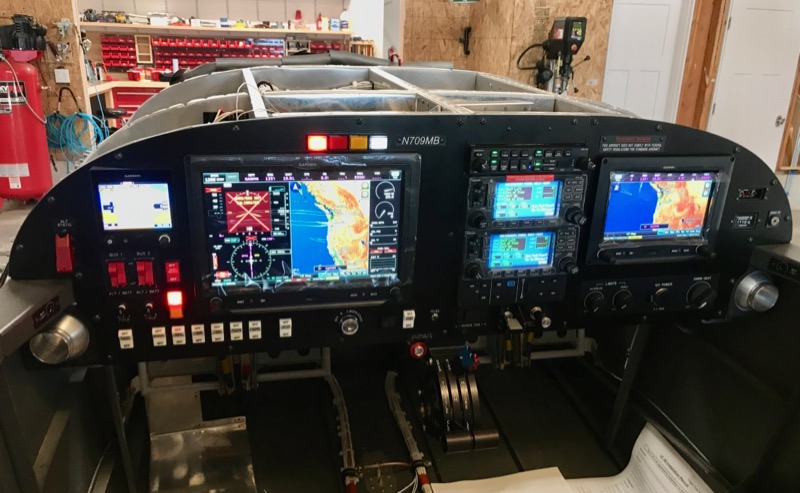
Here's the panel in darker lighting conditions, showing the backlit rocker switches. Even at minimum brightness the LED lamps in these switches are pretty bright – I'll deal with that later if need be.

One consequence of taking five years off from building is that parts of my panel have become positively antiquated. The GNS 430Ws especially are getting pretty long in the tooth, being now two generations out of date, although these particular units are practically brand-new. I did give serious consideration to tearing them out and rewriting the ratio stack for a more modern navigator, but in the end decided that I should stop redoing previous work and just focus on driving towards the finish line.

Late summer update

Sunday, September 20th, 2020

I have been working on various small jobs on the airplane project on and off all summer, but not much photo-worthy has transpired, so I've been remiss in posting updates. Mostly I've been finalizing wiring and panel details, securing wires that need to be secured, and finishing up the end stages of a panel overhaul which I'd begun before I moved, and hadn't mentioned here yet (more details on that later).

Believe it or not, a lot of work has been done here, although it's not at all apparent just by looking at it:

The panel plates and roll bar components are currently off getting powder coated, and when they're finished I should be able to install them for good.

Years of abuse and several hundred instances of me climbing in and of of the fuselage have left some chips in the cockpit paint, so I took the opportunity to touch up the cockpit rails and seatback bulkhead now while the panel is removed. Luckily the paint I used for my interior is still made (Rustoleum Textured in "dark pewter").

I've also been spending a lot of time working on another aviation-related thing which I will reveal eventually, so stay tuned for that…